o2 sensor simulator
 Jan 2, 2008, 04:36 AM
#1
Evolved Member
Thread Starter
iTrader: (8)

Join Date: Aug 2005
Location: Charlotte, NC
Posts: 4,015
Likes: 0
Received 0 Likes
on
0 Posts
o2 sensor simulator
for the rear o2 sensor (post-cat)
thought you guys might like this
Originally Posted by http://mkiv.com/techarticles/oxygen_sensor_simulator/
What is O2 sensor simulator?
The OBD-II cars (1996-1998) have the two O2 sensors to measure the amount of oxygen in the exhaust gas. First sensor is measuring it right after gases escape engine and this data is used to adjust fuel trim of the engine, as well as catch some faulty conditions. The second sensor is located after the catalic converter, and is used to detect the health of catalic converter. The ECU expects the signal from the sensor to be oscillating from below 0.4v to above 0.6v, but not above 1.2v, every few seconds when cruising.
If you install the aftermarket downpipe with no cat (which as we all know is purely for off-road applications) the ECU will detect this and indicate the error (MIL). The ECU is quite lazy at detection, and detects this condition approximately during second long trip. You can reset the ECU to clear the error code, but it's very inconvenient, as you don't really know if the error was because of oxygen sensor or some important thing is wrong and needs to be taken care of ASAP. It's also quite annoying.
How to build Your Own Oxygen Sensor Simulator!
The rest of the page shows how to build an oscillating signal generator with just the right frequency and voltage to fool the ECU. It is based on classical astable operating mode of 555 timer, so nothing revolutionary there. However we spent few days of fiddling and testing to get the right behavior.
The parts will cost about $15 - $20 from RadioShack. It's not that hard to build if you have some experience.
R1 100 K Ohm
R2 1 M Ohm
R3 100 K Ohm
R4 10 K Ohm
C1 4.7 uF
C2 22 uF
D1 1.7v@20mA LED
D2 1.7v@20mA LED
Hookup:
Power source Ignition, or to the ECU PIN #1 Ground One of the ground points or ECU PIN #80 OUT ECU PIN #47 (disconnect the O2 sensor wire)
Catalog part numbers from RadioShack stores:
(NOT for their online system)
276-309 5mm wide angle red led 1.7v, 20mA
276-1723 The 555 programmable timer
276-1995A The 8 pin socket for timer chip. It makes soldering safer and replacement easier
276-150A Generic PC board
64-3052A Pack of blue tap-in connectors
278-1225 Stranded wires (black, red and green)
270-1801 Small black plastic project box 3 x 2 x 1
272-1024 Capacitor, 4.7uF
272-1026 Capacitor, 22uF
Additional notes:
If you use different flavors of 555 timer chip or LEDs with different parameters you will need to readjust the values of R4 and R2 to get the interval and output voltage right.
Don't attach it directly to the ECU right after assembly. Instead attach it to the battery and check the output. You should get approximately 0v/0.7v flipping about every 3.3 seconds when the car is not running, and 0v/0.9v when the car is running. The current should stay below 10mA.
One LED should be always on whenever the power is supplied. Another LED indicates when the output signal is high, so it should go on and off with the signal.
When tapping the ECU wires, triple check everything before hooking up the oscillator. The power source should read 0v when the key is removed, about 12.6v when they key is at ACC and about 14.3 when the alternator is running. The resistance between ground wire and the body shield of the ECU should be 0 ohms. And it would be best if you run the car and monitor the voltage of the original oxygen sensor wire before cutting it to make sure you have indeed got the right one. The resistance between ECU PIN #47 and ground is about 1.3 to 1.6 M Ohm.
The original sensor should still be dangling around, or plugged into the downpipe. The reason is that ECU also monitors the resistance of heater circuit inside the sensor. If you want to COMPELTELY disconnect it, you will need to measure the resistance of the heater circuit and install the right resistor between ECU PIN #72 and ECU PIN #31 Anyway, there is no need to do it if you just leave O2 sensor alone and only intercept the oxygen signal wire.
Above testing and precautions will prevent you from frying the ECU and spending major $$$$. Anyway, I assume no responsibility if you still manage to do so.
The OBD-II cars (1996-1998) have the two O2 sensors to measure the amount of oxygen in the exhaust gas. First sensor is measuring it right after gases escape engine and this data is used to adjust fuel trim of the engine, as well as catch some faulty conditions. The second sensor is located after the catalic converter, and is used to detect the health of catalic converter. The ECU expects the signal from the sensor to be oscillating from below 0.4v to above 0.6v, but not above 1.2v, every few seconds when cruising.
If you install the aftermarket downpipe with no cat (which as we all know is purely for off-road applications) the ECU will detect this and indicate the error (MIL). The ECU is quite lazy at detection, and detects this condition approximately during second long trip. You can reset the ECU to clear the error code, but it's very inconvenient, as you don't really know if the error was because of oxygen sensor or some important thing is wrong and needs to be taken care of ASAP. It's also quite annoying.
How to build Your Own Oxygen Sensor Simulator!
The rest of the page shows how to build an oscillating signal generator with just the right frequency and voltage to fool the ECU. It is based on classical astable operating mode of 555 timer, so nothing revolutionary there. However we spent few days of fiddling and testing to get the right behavior.
The parts will cost about $15 - $20 from RadioShack. It's not that hard to build if you have some experience.
Electrical diagram:
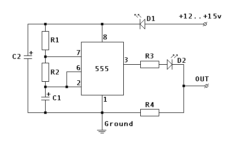
Components: R1 100 K Ohm
R2 1 M Ohm
R3 100 K Ohm
R4 10 K Ohm
C1 4.7 uF
C2 22 uF
D1 1.7v@20mA LED
D2 1.7v@20mA LED
Hookup:
Power source Ignition, or to the ECU PIN #1 Ground One of the ground points or ECU PIN #80 OUT ECU PIN #47 (disconnect the O2 sensor wire)
Catalog part numbers from RadioShack stores:
(NOT for their online system)
276-309 5mm wide angle red led 1.7v, 20mA
276-1723 The 555 programmable timer
276-1995A The 8 pin socket for timer chip. It makes soldering safer and replacement easier
276-150A Generic PC board
64-3052A Pack of blue tap-in connectors
278-1225 Stranded wires (black, red and green)
270-1801 Small black plastic project box 3 x 2 x 1
272-1024 Capacitor, 4.7uF
272-1026 Capacitor, 22uF
Additional notes:
If you use different flavors of 555 timer chip or LEDs with different parameters you will need to readjust the values of R4 and R2 to get the interval and output voltage right.
Don't attach it directly to the ECU right after assembly. Instead attach it to the battery and check the output. You should get approximately 0v/0.7v flipping about every 3.3 seconds when the car is not running, and 0v/0.9v when the car is running. The current should stay below 10mA.
One LED should be always on whenever the power is supplied. Another LED indicates when the output signal is high, so it should go on and off with the signal.
When tapping the ECU wires, triple check everything before hooking up the oscillator. The power source should read 0v when the key is removed, about 12.6v when they key is at ACC and about 14.3 when the alternator is running. The resistance between ground wire and the body shield of the ECU should be 0 ohms. And it would be best if you run the car and monitor the voltage of the original oxygen sensor wire before cutting it to make sure you have indeed got the right one. The resistance between ECU PIN #47 and ground is about 1.3 to 1.6 M Ohm.
The original sensor should still be dangling around, or plugged into the downpipe. The reason is that ECU also monitors the resistance of heater circuit inside the sensor. If you want to COMPELTELY disconnect it, you will need to measure the resistance of the heater circuit and install the right resistor between ECU PIN #72 and ECU PIN #31 Anyway, there is no need to do it if you just leave O2 sensor alone and only intercept the oxygen signal wire.
Above testing and precautions will prevent you from frying the ECU and spending major $$$$. Anyway, I assume no responsibility if you still manage to do so.
Last edited by DangerousDan; Jan 2, 2008 at 06:16 AM.
 Jan 2, 2008, 04:56 AM
#2
Evolved Member
Thread Starter
iTrader: (8)
Join Date: Aug 2005
Location: Charlotte, NC
Posts: 4,015
Likes: 0
Received 0 Likes
on
0 Posts
someone can get the correct pins for our ecu and post them here, I'm going back to my research
EDIT: pin 116 white wire for heated o12 sensor rear. using any ground and power wires should work.
EDIT: pin 116 white wire for heated o12 sensor rear. using any ground and power wires should work.
Last edited by DangerousDan; Jan 2, 2008 at 06:21 AM.
Jan 2, 2008, 06:15 AM
#3
Evolved Member
Thread Starter
iTrader: (8)
Join Date: Aug 2005
Location: Charlotte, NC
Posts: 4,015
Likes: 0
Received 0 Likes
on
0 Posts
it also is beginning to look like you can simulate the o2 sensor heater circuit with just a resistor. I will have more on this later, but a high wattage (at least 20watt) resistor of ~12-20ohms should emulate the heater. it will get hot (it's enough current for a heater circuit, duh) so you should be sure to isolate it from flammables.
pin 18, blue yellow wire. I would do this under the car anyway, since you have to put the resistor inline and it gets hot, but now you have the wire color (unless it changes at a connector somewhere)
pin 18, blue yellow wire. I would do this under the car anyway, since you have to put the resistor inline and it gets hot, but now you have the wire color (unless it changes at a connector somewhere)
Last edited by DangerousDan; Jan 2, 2008 at 06:23 AM.
 Jan 2, 2008, 07:50 AM
#5
Evolved Member
Thread Starter
iTrader: (8)
Join Date: Aug 2005
Location: Charlotte, NC
Posts: 4,015
Likes: 0
Received 0 Likes
on
0 Posts
yeah, I have both now. one for the inefficient cat and one for bad heater circuit I figure I can do both these and just cut the fugger out of the equation. I'm still gonna run a cat, but now I don't have to worry about all the "custom" wiring I've been doing
I figure I can do both these and just cut the fugger out of the equation. I'm still gonna run a cat, but now I don't have to worry about all the "custom" wiring I've been doing
Jan 2, 2008, 11:33 AM
#6
I have that ghetto antifouler setup running now (basically a sparkplug defouler..) and it works 90% of the time, but everyonce in a while on long trips it'll throw the P0171 code (bank 1 lean) so I think I'll rig up one of these and get rid of it altogether. Thanks for the find Dan.
Trending Topics
Jan 4, 2008, 06:26 PM
#9
Evolved Member
Thread Starter
iTrader: (8)
Join Date: Aug 2005
Location: Charlotte, NC
Posts: 4,015
Likes: 0
Received 0 Likes
on
0 Posts
 the information I found said it would be ~20 to purchase everything. that's why I posted the ~40 price tag for one already built. some people can't do this stuff. I know when I tried to repair my tv myself I decided it was the soldering iron
Jan 6, 2008, 08:42 AM
the information I found said it would be ~20 to purchase everything. that's why I posted the ~40 price tag for one already built. some people can't do this stuff. I know when I tried to repair my tv myself I decided it was the soldering iron
Jan 6, 2008, 08:42 AM
#10

I built this circuit once about 10 years ago. It worked and only needed the addition of an RC circuit on the output. It should work but a lot of the newer ECUs are pretty smart about detecting bad O2 sensors because of the US's requirement for a cat to last 100k miles. I'm trying to talk one of the piggyback manufacturers into implementing a similar feature but am not having much luck.
For the O2 heater problem you can just leave your factory rear O2 sensor hooked up and just cut the signal wire- this way the heater will still operate normally and the ECU will be happy with it.
For the O2 heater problem you can just leave your factory rear O2 sensor hooked up and just cut the signal wire- this way the heater will still operate normally and the ECU will be happy with it.
Jan 6, 2008, 09:12 AM
#12
R3 and R4 make a voltage divider but this is based on VCC which on a running car is going to be about 14v. In this case the output would probably be a little too high but it then relies on the voltage drop of D2. Before hooking up the output you should measure it with a DVM to make sure the output isn't too high or low. If it is then try increasing or decreasing R3. You could also replace it with an 8K (digikey CMF8.06KHFCT-ND) and put a 4k trimmer (digikey part T7YA-4.7K-ND) in it's place.
The speed is going to be dictated by R1, R2 and C1. C2 is only in there for noise. The forumula is f = 1/(.693 * C1 * (R1 + 2 * R2)). The pulsewidth is dictated by the ratio since the RC circuit charges and discharges through each.
time1 = .693 * (R1+R2) * C1
time2 = .693 * R2 * C1
Sum and short of it - try the circuit and if it doesn't work you can try changing the components outlined above.
Jan 6, 2008, 11:14 AM
#13
Evolved Member
Thread Starter
iTrader: (8)
Join Date: Aug 2005
Location: Charlotte, NC
Posts: 4,015
Likes: 0
Received 0 Likes
on
0 Posts
I built this circuit once about 10 years ago. It worked and only needed the addition of an RC circuit on the output. It should work but a lot of the newer ECUs are pretty smart about detecting bad O2 sensors because of the US's requirement for a cat to last 100k miles. I'm trying to talk one of the piggyback manufacturers into implementing a similar feature but am not having much luck.
For the O2 heater problem you can just leave your factory rear O2 sensor hooked up and just cut the signal wire- this way the heater will still operate normally and the ECU will be happy with it.
For the O2 heater problem you can just leave your factory rear O2 sensor hooked up and just cut the signal wire- this way the heater will still operate normally and the ECU will be happy with it.
this is the first time I have gotten this code. I will post up when I decide to take care of this CEL, it won't be too long because my inspection is due in March.
Jan 6, 2008, 11:42 AM
#14
No, don't let it hang under the car - leave it plugged in the exhaust. As soon as you get a drop of water on a hot O2 sensor they have a bad tendancy for the ceramic element to crack. That's an expensive lesson I learned years ago with the NTK L1H1 ($400-$500) for a sensor.
-Michael
-Michael