CrAnSwIcK's 4G69 Build: Phase 2
 Sep 5, 2011, 02:30 PM
#31
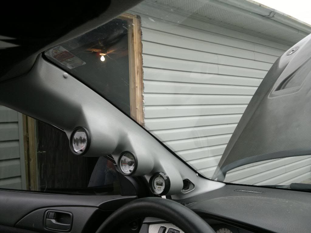
Well, i got a few more things done this weekend....have a look, too lazy for step by step, but it's pretty straight forward...there's enough room between the gauge pod, and stock pillar to run wires without cutting the stock pillar, i just removed the speaker cover with a hobby knife, and ran the wires through that, around the stock tweeter, and then glued the speaker cover to the new pod, as it has the speaker cut-out. you don't have to line the edges of the pod right up with stock pillar, you can leave like a 1/4 inch, cause the one side is hidden by the weather stripping. and the other side is hidden by the black border on the edges of the windshield, this will leave plenty of room for the wires to run....


 Sep 5, 2011, 04:23 PM
#33
i thought about it, but the stock look, is not too bad, i'm not really big on aesthetics, i'd rather spend an hour pulling a transmission, than spend 5 minutes painting a panel, besides i hate removing interior panels/dash etc. I like metal, nuts and bolts...lol, plastic makes me mad and i always end up breaking it...installing the gauges was enough head ache for me.
in case anyone is wondering, the 10A fuse for door locks makes a good constant 12v, and for my switching 12v i used the 7.5A cluster fuse, it works on ignition, but it doesn't turn on and off with the cluster lighting, it's always on with ignition, which sucks, but oh well, i'll figure it out later. and i found a nice little ground as well, i'll post pics.
in case anyone is wondering, the 10A fuse for door locks makes a good constant 12v, and for my switching 12v i used the 7.5A cluster fuse, it works on ignition, but it doesn't turn on and off with the cluster lighting, it's always on with ignition, which sucks, but oh well, i'll figure it out later. and i found a nice little ground as well, i'll post pics.
Last edited by CrAnSwIcK; Sep 5, 2011 at 04:46 PM.
Sep 5, 2011, 09:13 PM
#36
well, it's fed 0-5v i'm pretty sure, if the stock sensor has the same output, i'll just splice into the harness, because the sensor that came with the gauge is freakin' huge! so i would have to mount it remotely, now my oil feed for the turbo is through an adapter that replaces the stock sensor on the back of the block below the intake manifold, but i don't want this huge sending unit for the gauge hanging off of that, so i would have to mount it remotely, which means time, plus money as i would need an extra oil line, plus fittings.
Sep 5, 2011, 09:52 PM
#37
Ah 10-4. I'm running the prosport gauges. The peak warning ones that are thin. The sensor is pretty small for it and it's a plug. You should look into some prosport ones.
Ps, I shot you a text earlier regarding the whole lip thing, but it got deleted. Lol pm me if you didn't get it and I'll fill you in through pm
Ps, I shot you a text earlier regarding the whole lip thing, but it got deleted. Lol pm me if you didn't get it and I'll fill you in through pm
Last edited by roblaza; Sep 5, 2011 at 09:55 PM.
Sep 5, 2011, 10:07 PM
#38
got it...now to find one, lol...you the guinea pig? i got a lot on my plate right now with the car...lol
few more pics....
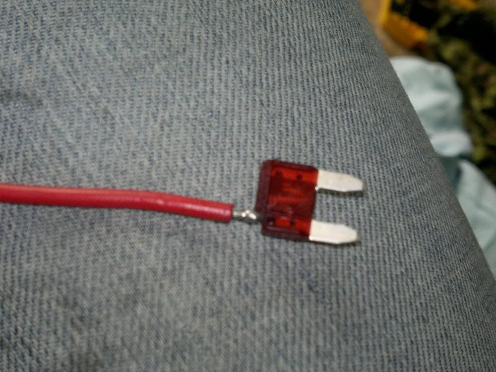
Here's a little how-to: Make your own "add-a-circuit". Step 1. Figure out what source you want to use. Step 2. pull the fuse out. Step 3. use a hobby knife and hack the top corner off the fuse off to expose the top of one of the contacts. Step 4. cut a small section of wire and strip the end leaving only about 1/8 of an inch of bare copper. tin the bare copper with solder, flux helps. Step 5. Tin the exposed contact of the fuse, and solder the wire to it.
here's how it looks:
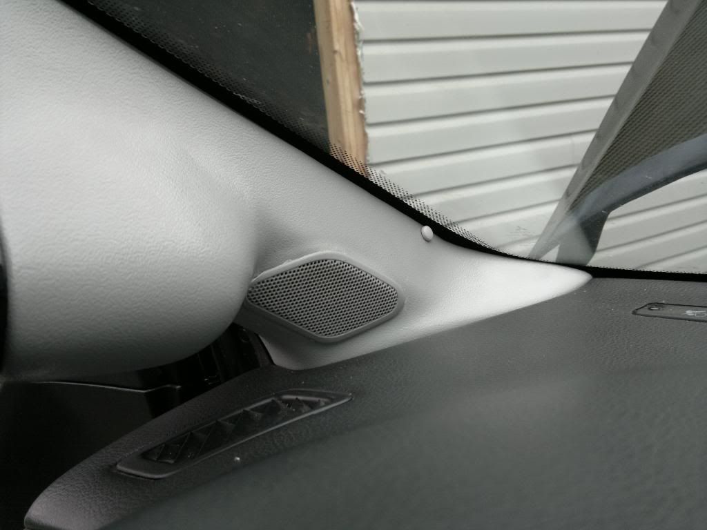
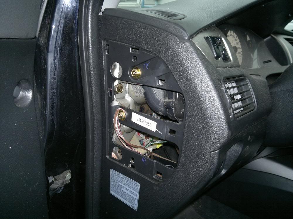
Here's that super convenient grounding location i was talking about: you can reach your hand up on the inside and pop the panel off by hand, i verified this ground with a multi-meter, and added an extra washer to sandwich the bare wire ends.
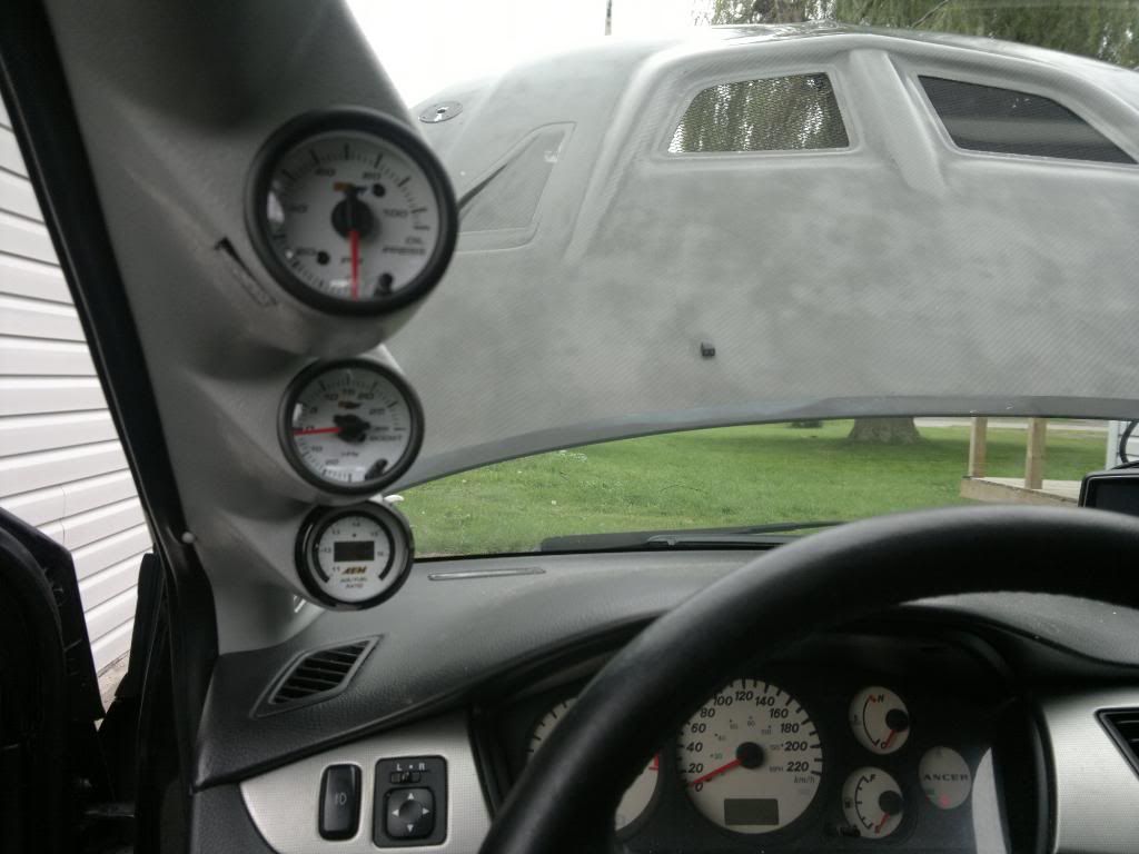
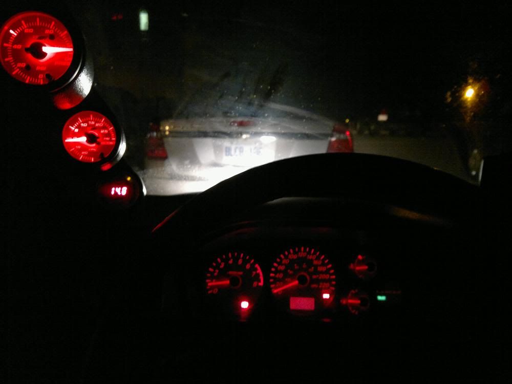
And here are all the gauges wired for power, but no inputs.
few more pics....
Here's a little how-to: Make your own "add-a-circuit". Step 1. Figure out what source you want to use. Step 2. pull the fuse out. Step 3. use a hobby knife and hack the top corner off the fuse off to expose the top of one of the contacts. Step 4. cut a small section of wire and strip the end leaving only about 1/8 of an inch of bare copper. tin the bare copper with solder, flux helps. Step 5. Tin the exposed contact of the fuse, and solder the wire to it.
here's how it looks:
Here's that super convenient grounding location i was talking about: you can reach your hand up on the inside and pop the panel off by hand, i verified this ground with a multi-meter, and added an extra washer to sandwich the bare wire ends.
And here are all the gauges wired for power, but no inputs.
Sep 6, 2011, 06:51 PM
#42
*EDIT*
Ok, so our oil pressure sensor is a switch, rather than a sending unit, so it does not output any signals other than on or off...i'm going to try to find a smaller sending unit.
Last edited by CrAnSwIcK; Sep 6, 2011 at 09:27 PM.
 lol yea. Max oil pressure is always good and well the zero boost just proves that she can go fast right lol. That sucks with the sensor to, hopefully all turns out good.
Sep 19, 2011, 04:13 AM
lol yea. Max oil pressure is always good and well the zero boost just proves that she can go fast right lol. That sucks with the sensor to, hopefully all turns out good.
Sep 19, 2011, 04:13 AM
#44
Well, it all turned out...instead of pictures i have a video of the oil pressure gauge working, and what i did to get it to work. and it's pretty slick if i say so myself.
That will be later though, cause i don't have an MP4 codec, so i'll boot into Linux later and convert it to avi for editing.
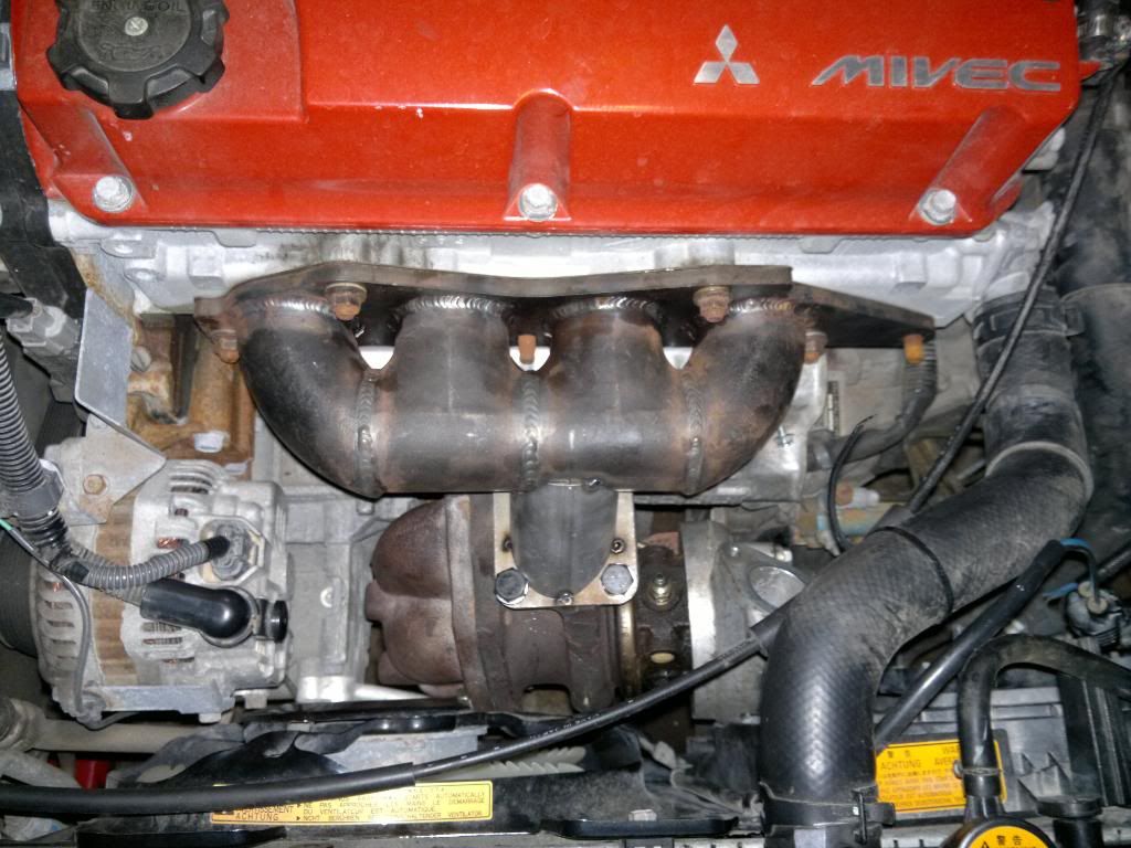
On the the project, check my DIY Log Manifold thread for details on the manifold. If you don't check it it out, know that it's only tacked, and this is phase two of fitment.
So here it is bolted up...
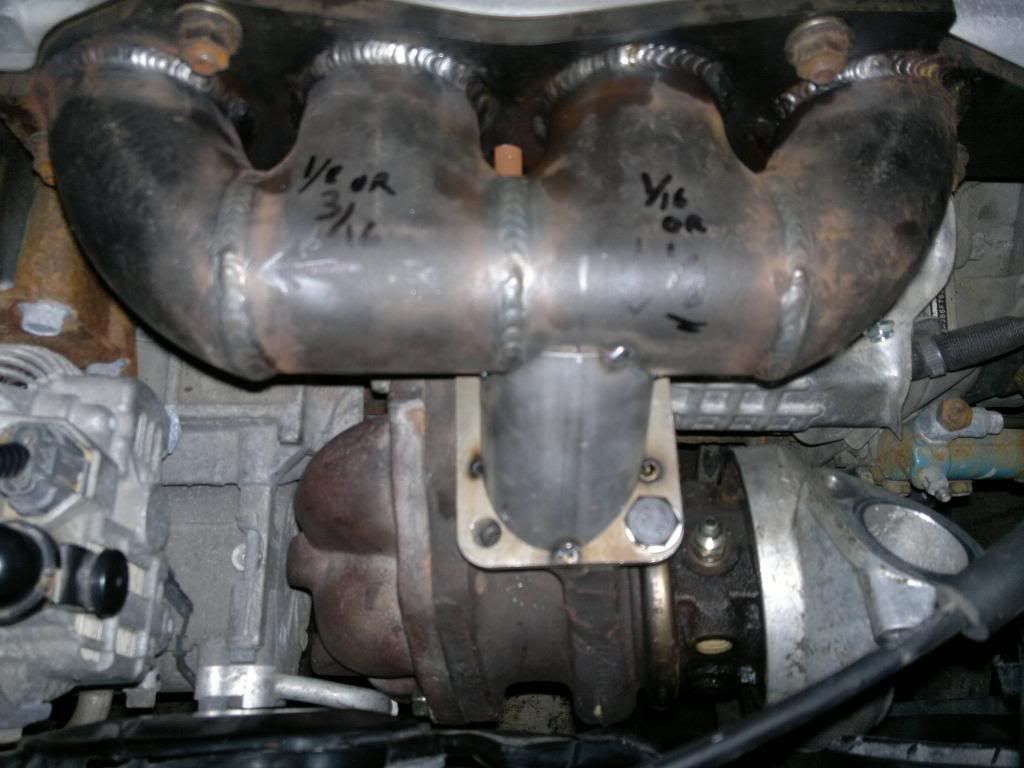
And here, you can see it's off by a little bit and is running into the main radiator fan.
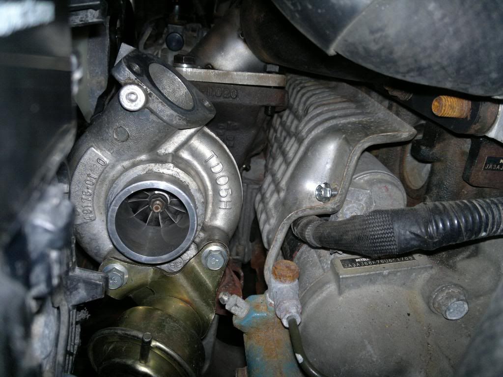
And here you can see there is quite a bit of clearanceon the engine side, so i'll be moving the flange backward a bit, to get it off the rad fan, and closer to the engine.What really funny is look how the heat shield for the starter appears to have been designed for the wastegate actuator...i thought this was gold!
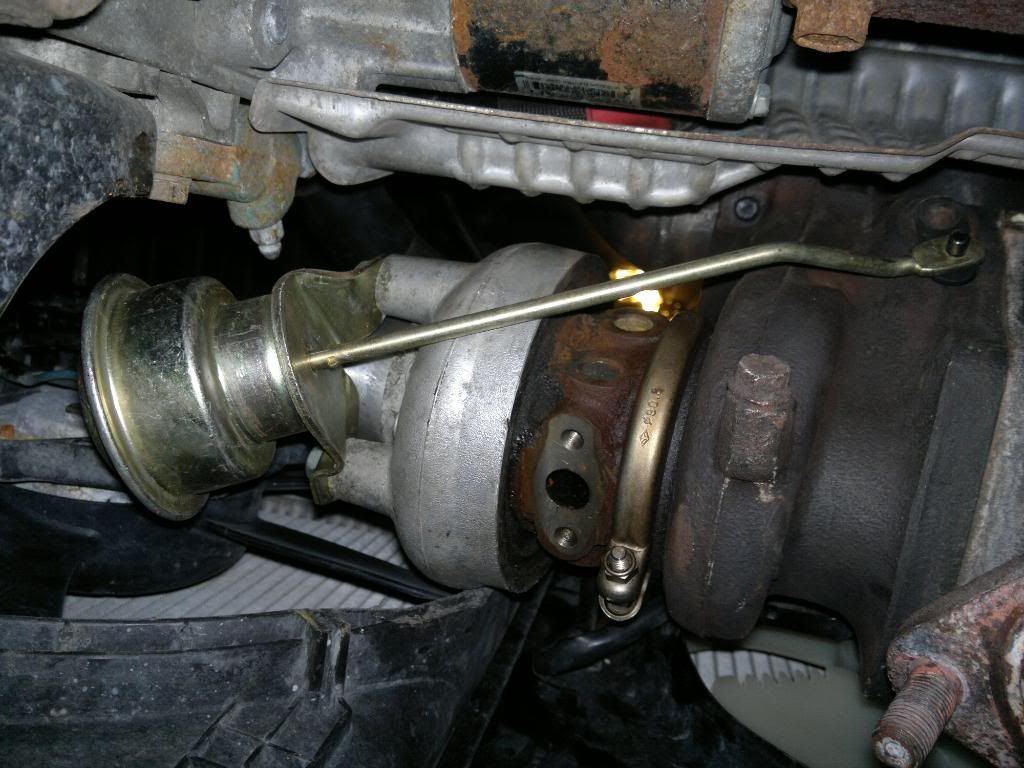
All in all, i think it's coming along slowly but surely, as it stands, i'm confident this can be done without removing the stock fans, and to be honest, the only reason this is an issue is because i'm using the stock 14b O2 housing, and internal wastegate, so angles and distances are super critical. Otherwise if you went external waste gate, your downpipe could go where ever you want. Mine has to accommodate stock parts for a different car, but it's not too bad so far. Hope you enjoyed the update, and stay tuned for the video lol! it involves me crawling around under the car on my gravel driveway.
That will be later though, cause i don't have an MP4 codec, so i'll boot into Linux later and convert it to avi for editing.
On the the project, check my DIY Log Manifold thread for details on the manifold. If you don't check it it out, know that it's only tacked, and this is phase two of fitment.
So here it is bolted up...
And here, you can see it's off by a little bit and is running into the main radiator fan.
And here you can see there is quite a bit of clearanceon the engine side, so i'll be moving the flange backward a bit, to get it off the rad fan, and closer to the engine.What really funny is look how the heat shield for the starter appears to have been designed for the wastegate actuator...i thought this was gold!
All in all, i think it's coming along slowly but surely, as it stands, i'm confident this can be done without removing the stock fans, and to be honest, the only reason this is an issue is because i'm using the stock 14b O2 housing, and internal wastegate, so angles and distances are super critical. Otherwise if you went external waste gate, your downpipe could go where ever you want. Mine has to accommodate stock parts for a different car, but it's not too bad so far. Hope you enjoyed the update, and stay tuned for the video lol! it involves me crawling around under the car on my gravel driveway.
Last edited by CrAnSwIcK; Sep 19, 2011 at 04:15 AM.
Sep 27, 2011, 06:36 PM
#45
Okay I'm commenting on your build. Time for an update!
Ps please inform me as to how you installed your sensor for the oil psi. I have to hook mine up again as I broke the sensor off pulling into my driveway last winter... Cold plastic cracks quite easily.
Ps please inform me as to how you installed your sensor for the oil psi. I have to hook mine up again as I broke the sensor off pulling into my driveway last winter... Cold plastic cracks quite easily.