4G69 Tear Down Detail
 Jan 28, 2015, 07:20 AM
#1
4G69 Tear Down Detail
So I mentioned possibly making this thread a while back and a few people seemed interested in it. Just up front this wont be an entire tear down. But it will show most of the engine and I will be trying to collect as mush information about it as I can. Keep in mind I might not always have the best grammer or writing because I'll be doing the write up as I am working on the engine and trying to take pictures. So forgive me ahead of time please. I am also not a professional mechanic so If I do something weird or dumb let me know politely, this is a big learning experience for me too, and I figured sharing it with everyone would be useful.
I'm planning to follow the Factory Service Manual as closely as I can. So I'll break this down into chapters in a similar way that the book does. If its not against some rule I dont remember I might try to post some screenshots from the FSM to explain things a bit better from time to time. Also the AC compressor, header, and starter have all been previously removed so you wont see details on that in this thread. However I might add them and a few other details whenever I am assembling the engine just to try cramming as much info as I can into this thread.
I want to apologize ahead of time for some crappy pictures. Im currently using my cellphone and it sucks. I had a small nikon camera I was going to use but it seems to be dead... I'll have some better pics once I get ahold of a camera.
================================================== ======================
::CHAPTERS::
1// Accessories, Pulleys, Ignition system
2// Timing belt
3// Fuel and Emissions Parts
4// Intake Manifold and Water Pump
5// Sensors
6// Cylinder Head Removal
7// Oil System Removal
X// QnA Section >>Open<<
================================================== ======================
>: THE PROJECT :<
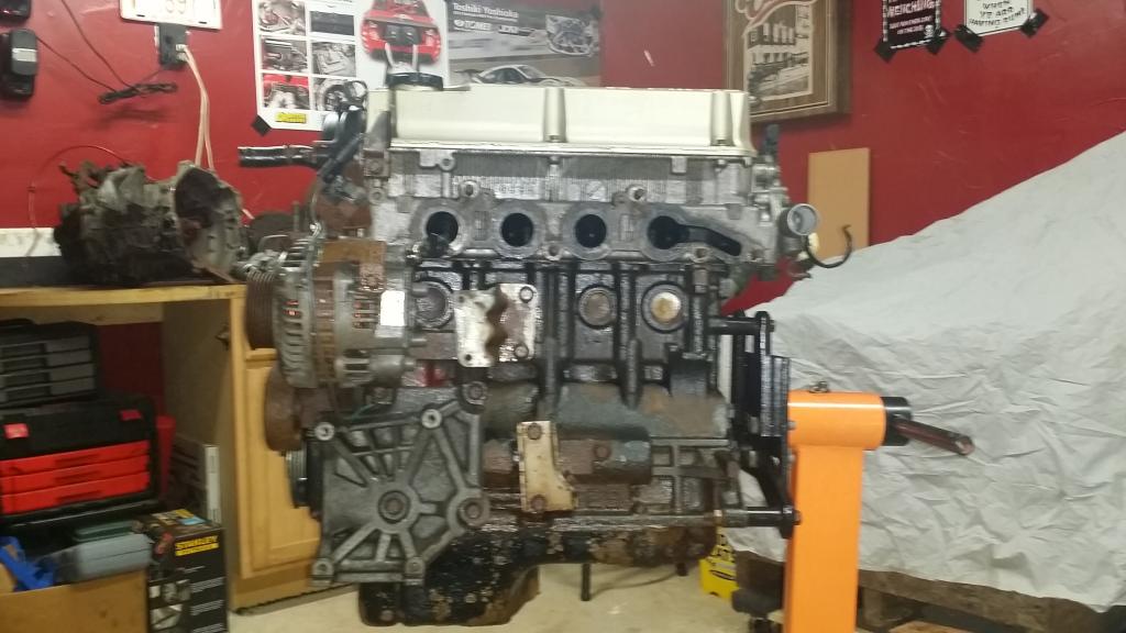
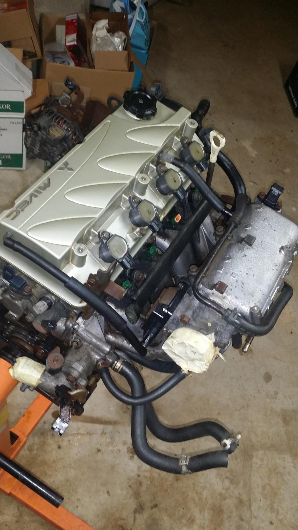
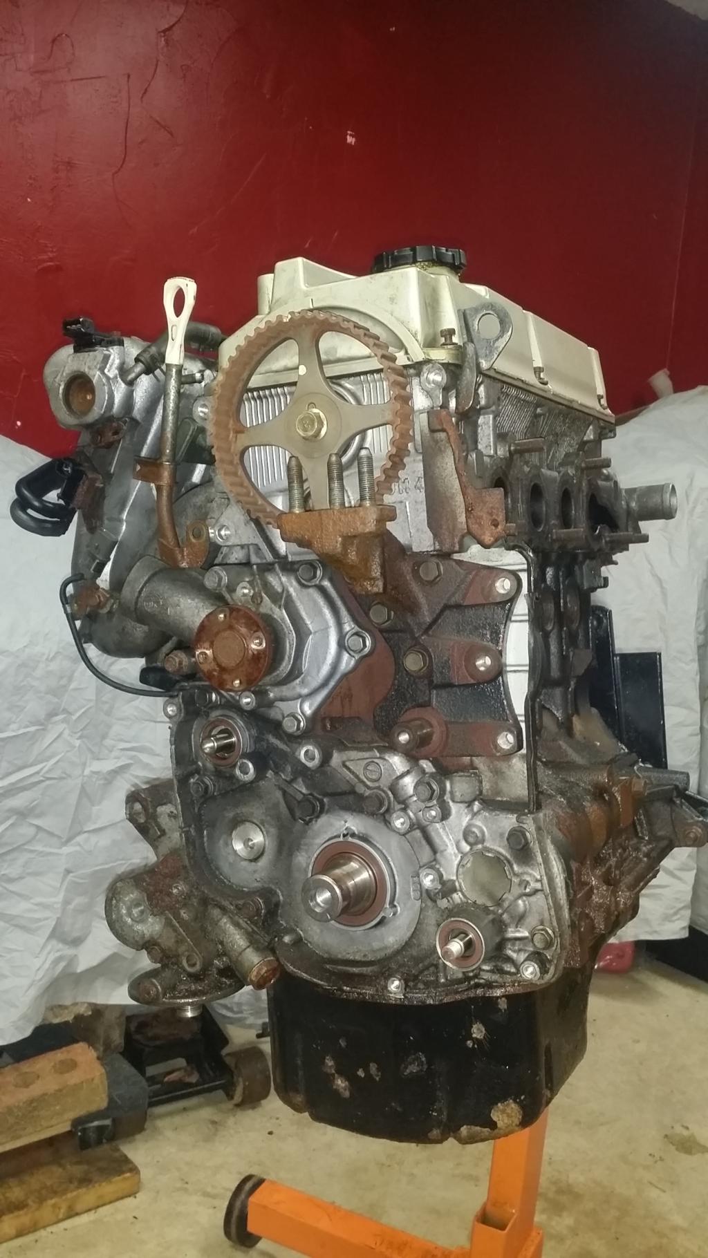
This engine came out of the car the previously belonged to Smike and Otter. It lived its life up north for a long time so there was a lot of rust. At this point I had dropped the engine and tranny from the car together, split off the tranny, and got the engine up on the stand. I went ahead and soaked the engine in PB blaster, and WD-40 to try penetrating some of the rust and lubricating the bolts and nuts. I brushed it down with a wire brush to etch up the rust and then sprayed it with some acid to eat away the chunks of rust. It still looks a little rusty here but trust me the big hunks and flaking pieces are all gone and it already looks much better at this point. Im excited to see the final product after I get the engine back together!
================================================== =======================
>: CHAPTER 1 :<
:// Accessories, Pulleys, and Ignition
Lets get to work!
FSM first addresses removing the Generator and Ignition system. This involves the Dipstick and guide, the auto tensioner, all the pulleys, some brackets, the alternator, coilpacks, spark plugs, camshaft position sensor, o-rings, and camshaft position sensing cylinder.
Before I get started I want to get a few things out of the way. Namely these hoses that arent going anywhere and the oil filter.
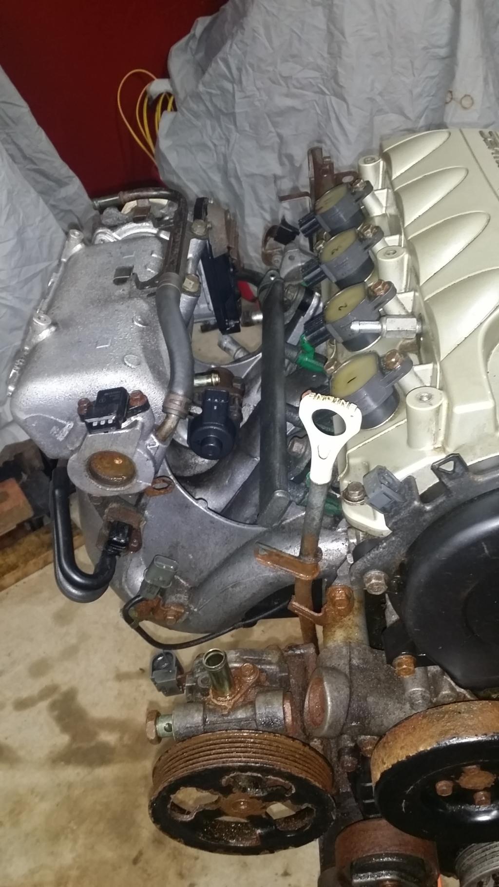
Alright if we follow the directions of the FSM the dipstick, tube, and its o-ring are first. But there was one small issue. I removed the Power Steering pump with the engine when I dropped it. So I'll have to get that out of the way first. So lets just focus on the PS for now. This is actually pretty simple. A few bolts and the PS pump and a bracket all come off as one.
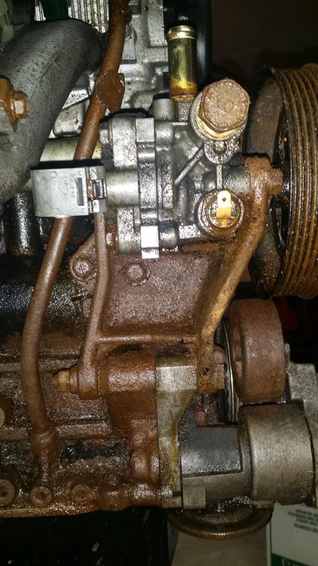
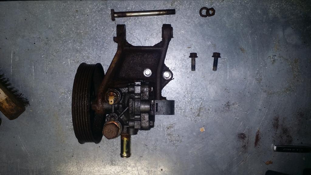
It will take a 14mm socket to get the horizontal bolt at the bottom of the bracket loose. Then 12mm socket and a short extension on the two just under the pump. Peck the long bolt the the 14mm nut was on until it comes out. Wiggle the bracket and pump back and forth until it comes free. This is what you should end up with.
This is probably as good a time as any to mention that you should be organized when removing parts, bolts, nuts, anything that you plan to use again. I learned the hard way on my old Eclipse that no matter how organized you think your mess may be, it never stays that way. You may come up with your own solution. Mine? Ziplock bags and a sharpie.
Now to the dipstick. There is a single 12mm bolt holding it in place. Now unless your engine is as rusted as mine you should be able to pull and twist to pull the tube out of the lower block. However mine is rusted in place and wont move. Plus its not in my way for what I will be doing so Im just freeing the tube from the Intake manifold then leaving it in place.
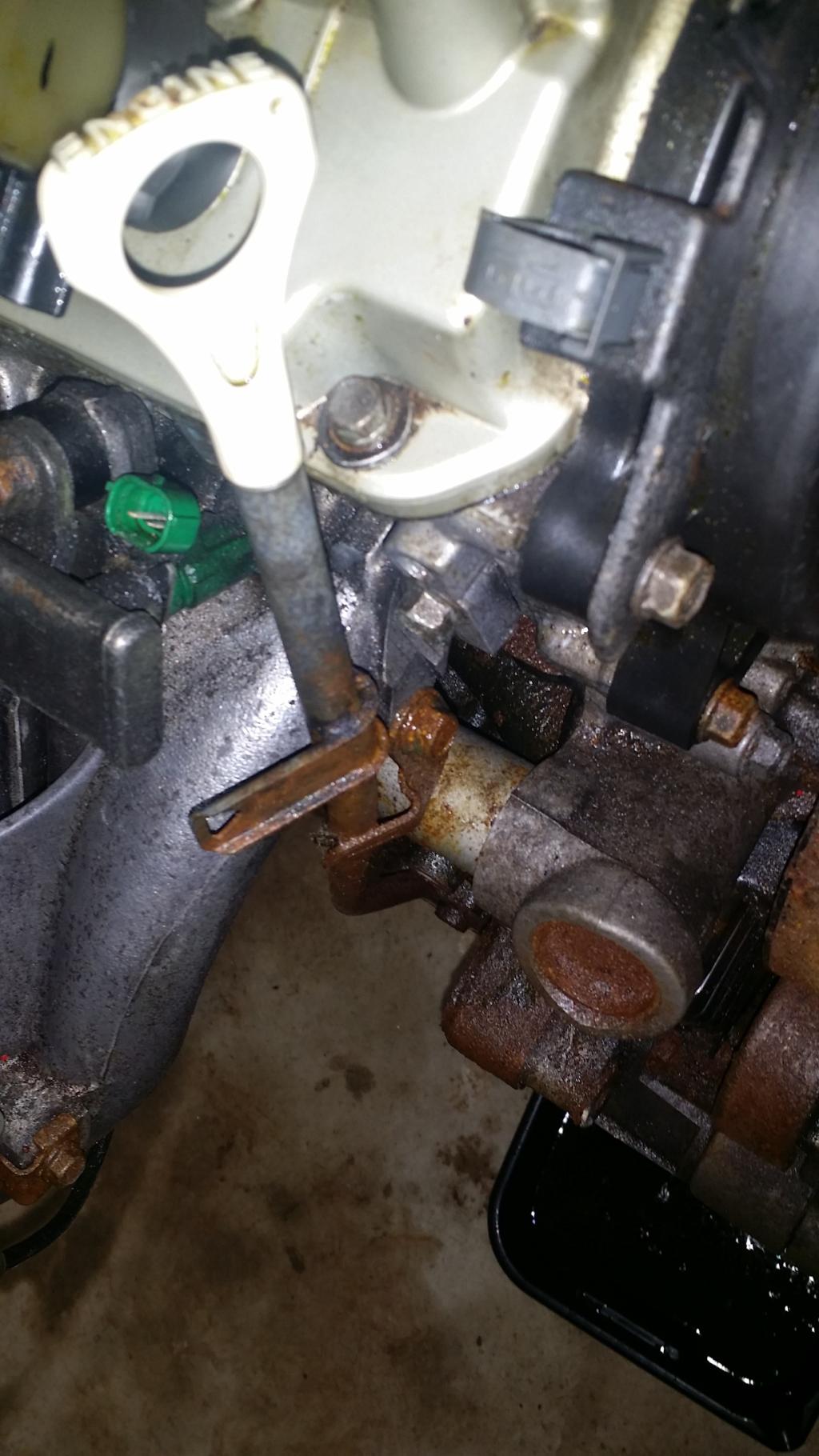
Next step is the pulleys. FSM starts with the auto tensioner. There is a 14mm bolt in the middle of the tensioner, and a 12mm just below and to the right. In this same pic you can see the 4 12mm bolts that hold the crankshaft pulley on, those are next right after the tensioner comes off.
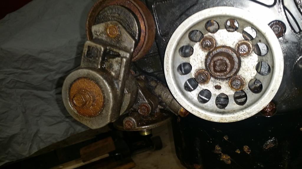
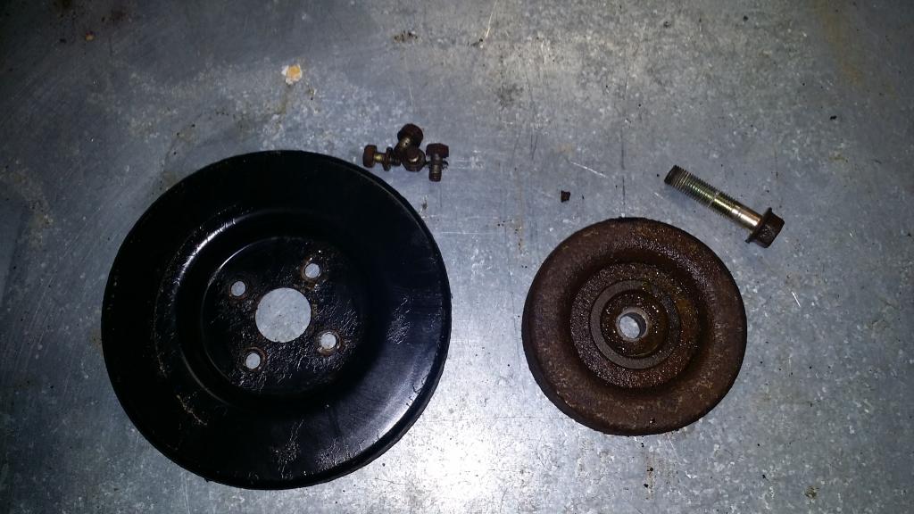
Tensioner came off easily, just remove the bolts and it falls off. However I need to make a note here for myself and anyone else who might be thinging about using the light weight crankshaft pulley. Please, use antiseize before installing the pulley. The bolts came out no problems but it was seized on still. Took a heat gun and an angry hammer to get it off.
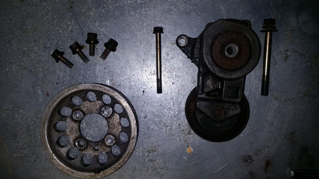
Next up is the water pump pulley, and idler pulley. Unless you got something to hold the water pump pulley still use a socket gun to get the 10mm bolts out. Idler pulley took a 14mm socket and a bit of muscle to break loose.
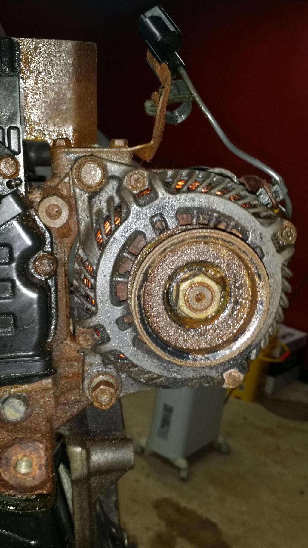
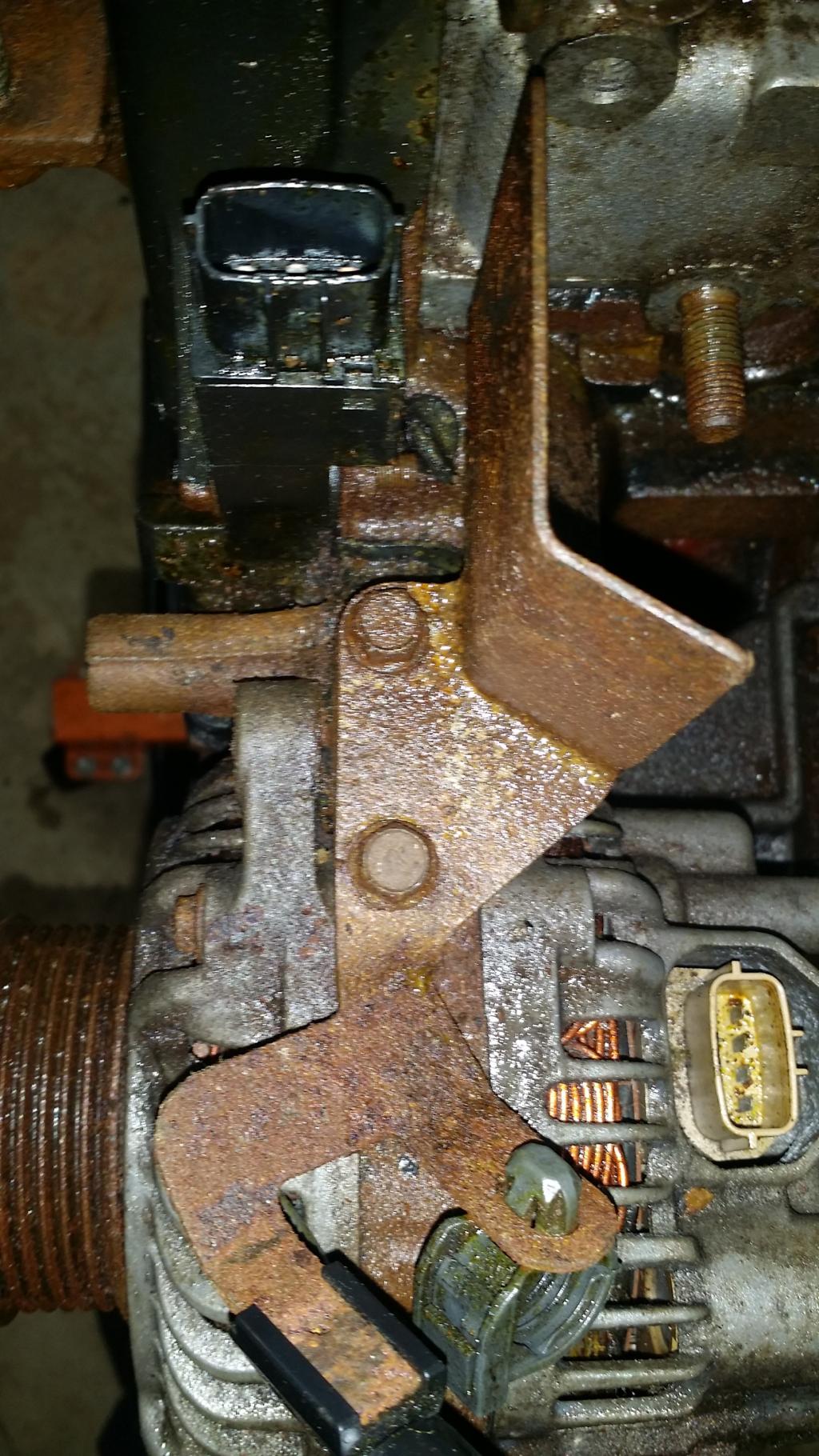
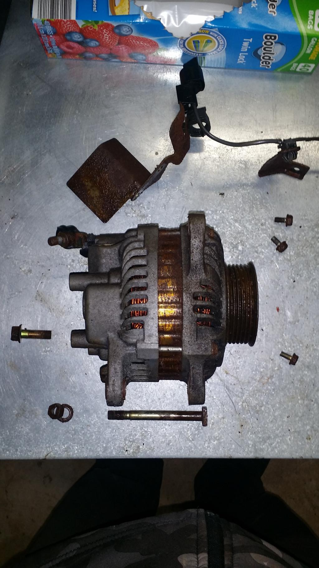
Next step is to get the alternator off. Takes a 14mm socket, nut and crush washer on the bottom, bolt on the top. Peck out the bolt on the bottom with a hammer. There is also a bracket right on top of the alternator that the FSM says to remove it has two 10mm bolts holding it on. Then just wiggle the alternator free.
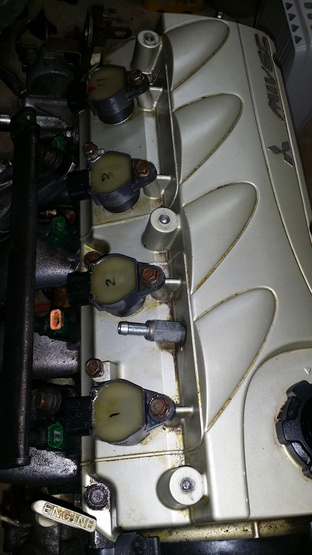
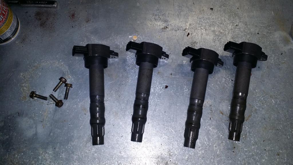
Next step is the coilpacks, spark plugs, and camshaft position sensor unit. Im leaving the spark plugs in for now, because for some illogical reason im afraid of dropping something into the combustion chamber... lol And I'll be leaving the camshaft postion sensor housing on, just removing the sensor. So to get out the coilpacks it takes a 10mm socket for each of the 4 bolts. And holding the camshaft position sensor itself is another 10mm bolt, which I forgot to get a picture of. Sorry.
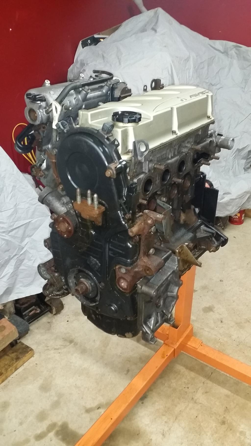
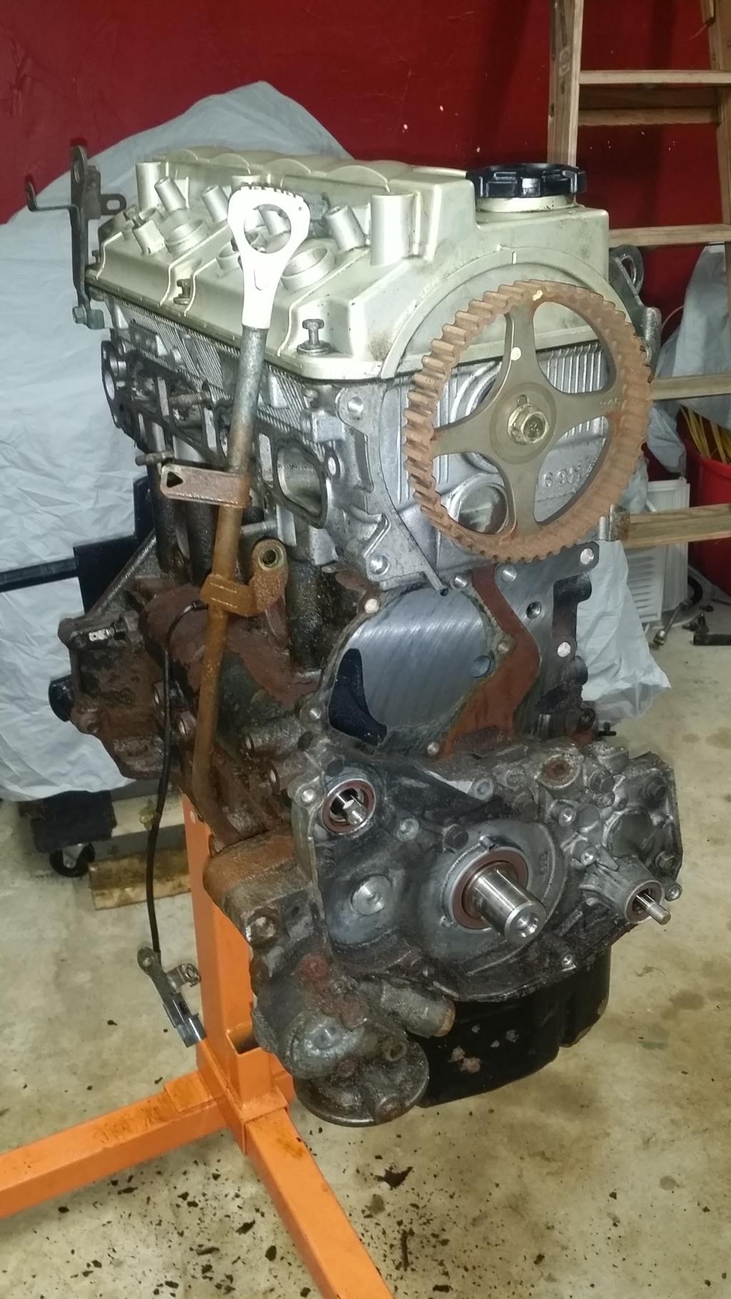
And that it's it for the first section of the FSM, so thats the end of Chapter 1 of our tear down. Next up is the timing belt and all of it's goodies. Here is a pic of the progress made so far.

I'm planning to follow the Factory Service Manual as closely as I can. So I'll break this down into chapters in a similar way that the book does. If its not against some rule I dont remember I might try to post some screenshots from the FSM to explain things a bit better from time to time. Also the AC compressor, header, and starter have all been previously removed so you wont see details on that in this thread. However I might add them and a few other details whenever I am assembling the engine just to try cramming as much info as I can into this thread.
I want to apologize ahead of time for some crappy pictures. Im currently using my cellphone and it sucks. I had a small nikon camera I was going to use but it seems to be dead... I'll have some better pics once I get ahold of a camera.
================================================== ======================
::CHAPTERS::
1// Accessories, Pulleys, Ignition system
2// Timing belt
3// Fuel and Emissions Parts
4// Intake Manifold and Water Pump
5// Sensors
6// Cylinder Head Removal
7// Oil System Removal
X// QnA Section >>Open<<
================================================== ======================
>: THE PROJECT :<
This engine came out of the car the previously belonged to Smike and Otter. It lived its life up north for a long time so there was a lot of rust. At this point I had dropped the engine and tranny from the car together, split off the tranny, and got the engine up on the stand. I went ahead and soaked the engine in PB blaster, and WD-40 to try penetrating some of the rust and lubricating the bolts and nuts. I brushed it down with a wire brush to etch up the rust and then sprayed it with some acid to eat away the chunks of rust. It still looks a little rusty here but trust me the big hunks and flaking pieces are all gone and it already looks much better at this point. Im excited to see the final product after I get the engine back together!
================================================== =======================
>: CHAPTER 1 :<
:// Accessories, Pulleys, and Ignition
Lets get to work!
FSM first addresses removing the Generator and Ignition system. This involves the Dipstick and guide, the auto tensioner, all the pulleys, some brackets, the alternator, coilpacks, spark plugs, camshaft position sensor, o-rings, and camshaft position sensing cylinder.
Before I get started I want to get a few things out of the way. Namely these hoses that arent going anywhere and the oil filter.
Alright if we follow the directions of the FSM the dipstick, tube, and its o-ring are first. But there was one small issue. I removed the Power Steering pump with the engine when I dropped it. So I'll have to get that out of the way first. So lets just focus on the PS for now. This is actually pretty simple. A few bolts and the PS pump and a bracket all come off as one.
It will take a 14mm socket to get the horizontal bolt at the bottom of the bracket loose. Then 12mm socket and a short extension on the two just under the pump. Peck the long bolt the the 14mm nut was on until it comes out. Wiggle the bracket and pump back and forth until it comes free. This is what you should end up with.
This is probably as good a time as any to mention that you should be organized when removing parts, bolts, nuts, anything that you plan to use again. I learned the hard way on my old Eclipse that no matter how organized you think your mess may be, it never stays that way. You may come up with your own solution. Mine? Ziplock bags and a sharpie.
Now to the dipstick. There is a single 12mm bolt holding it in place. Now unless your engine is as rusted as mine you should be able to pull and twist to pull the tube out of the lower block. However mine is rusted in place and wont move. Plus its not in my way for what I will be doing so Im just freeing the tube from the Intake manifold then leaving it in place.
Next step is the pulleys. FSM starts with the auto tensioner. There is a 14mm bolt in the middle of the tensioner, and a 12mm just below and to the right. In this same pic you can see the 4 12mm bolts that hold the crankshaft pulley on, those are next right after the tensioner comes off.
Tensioner came off easily, just remove the bolts and it falls off. However I need to make a note here for myself and anyone else who might be thinging about using the light weight crankshaft pulley. Please, use antiseize before installing the pulley. The bolts came out no problems but it was seized on still. Took a heat gun and an angry hammer to get it off.
Next up is the water pump pulley, and idler pulley. Unless you got something to hold the water pump pulley still use a socket gun to get the 10mm bolts out. Idler pulley took a 14mm socket and a bit of muscle to break loose.
Next step is to get the alternator off. Takes a 14mm socket, nut and crush washer on the bottom, bolt on the top. Peck out the bolt on the bottom with a hammer. There is also a bracket right on top of the alternator that the FSM says to remove it has two 10mm bolts holding it on. Then just wiggle the alternator free.
Next step is the coilpacks, spark plugs, and camshaft position sensor unit. Im leaving the spark plugs in for now, because for some illogical reason im afraid of dropping something into the combustion chamber... lol And I'll be leaving the camshaft postion sensor housing on, just removing the sensor. So to get out the coilpacks it takes a 10mm socket for each of the 4 bolts. And holding the camshaft position sensor itself is another 10mm bolt, which I forgot to get a picture of. Sorry.
And that it's it for the first section of the FSM, so thats the end of Chapter 1 of our tear down. Next up is the timing belt and all of it's goodies. Here is a pic of the progress made so far.
Last edited by bakuro117; Feb 11, 2015 at 08:25 PM.

 Jan 28, 2015, 02:21 PM
#4
Newbie

Join Date: Jan 2015
Location: Calgary, AB
Posts: 12
Likes: 0
Received 0 Likes
on
0 Posts
Awesome, I can't wait to see more...mostly because there's no way I'd be able to do any of this without ending up with a heap of metal that was once an engine...but I'm more than happy being a spectator.
Jan 28, 2015, 08:50 PM
#5
>: CHAPTER 2 :<
:// Timing Belt Removal
Alright diving right in today. We have a lot of stuff to cover. According to the FSM this is actually Chapter 3. But I already had the exhaust off so I skipped that part. Removing the timing belt and all of its components actually involves 26 parts. Instead of listing them all lets just get started. This one might be longer than I expected.
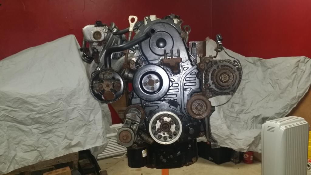
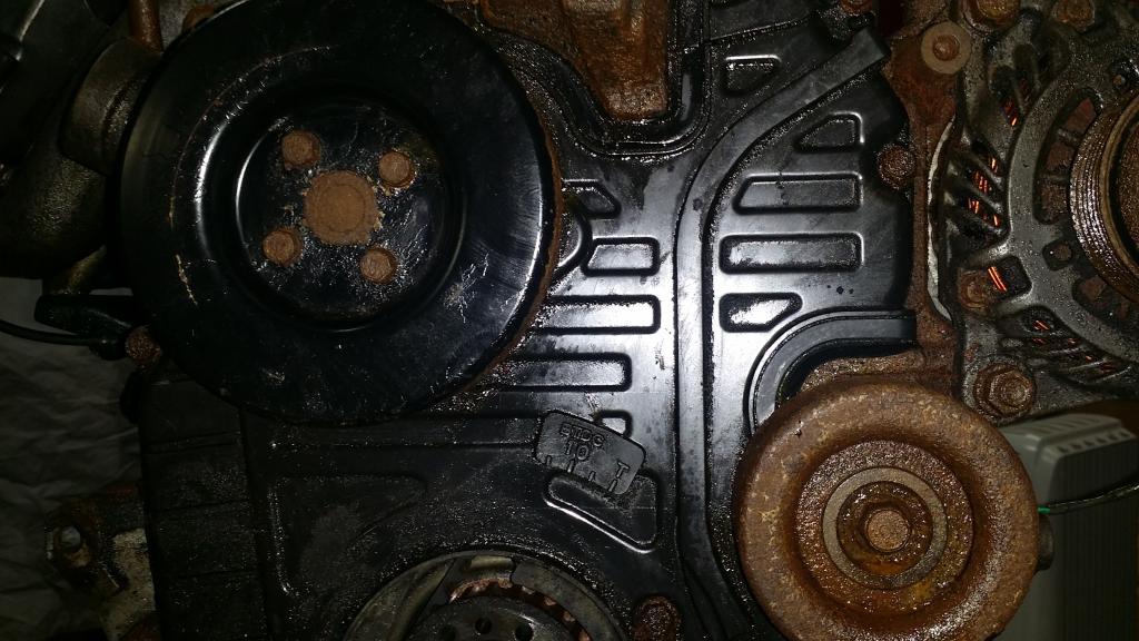
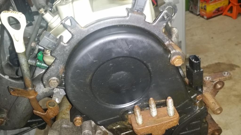
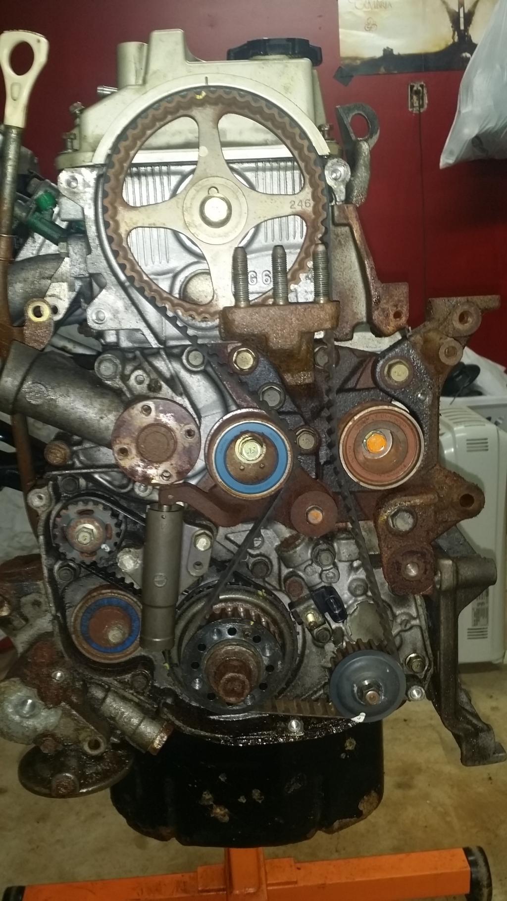
So starting from here we can see the black timing belt covers. The upper and lower. So we need to start with the upper cover and the metal bracket that holds the wiring harness where it goes over the engine.
This is a very simple process. The cover and bracket are only held on with three 12mm bolts. Remember the one on the front side is the long one.
Interestingly enough I expected to find the timing belt broken, shredded, or tucked down in the lower cover. But its not. It doesnt even have much play. Im actually beginning to wonder if I was told the right story about this car having bent valves because a bad tensioner caused the timing to skip... Well we will see when we get there. Moving on!
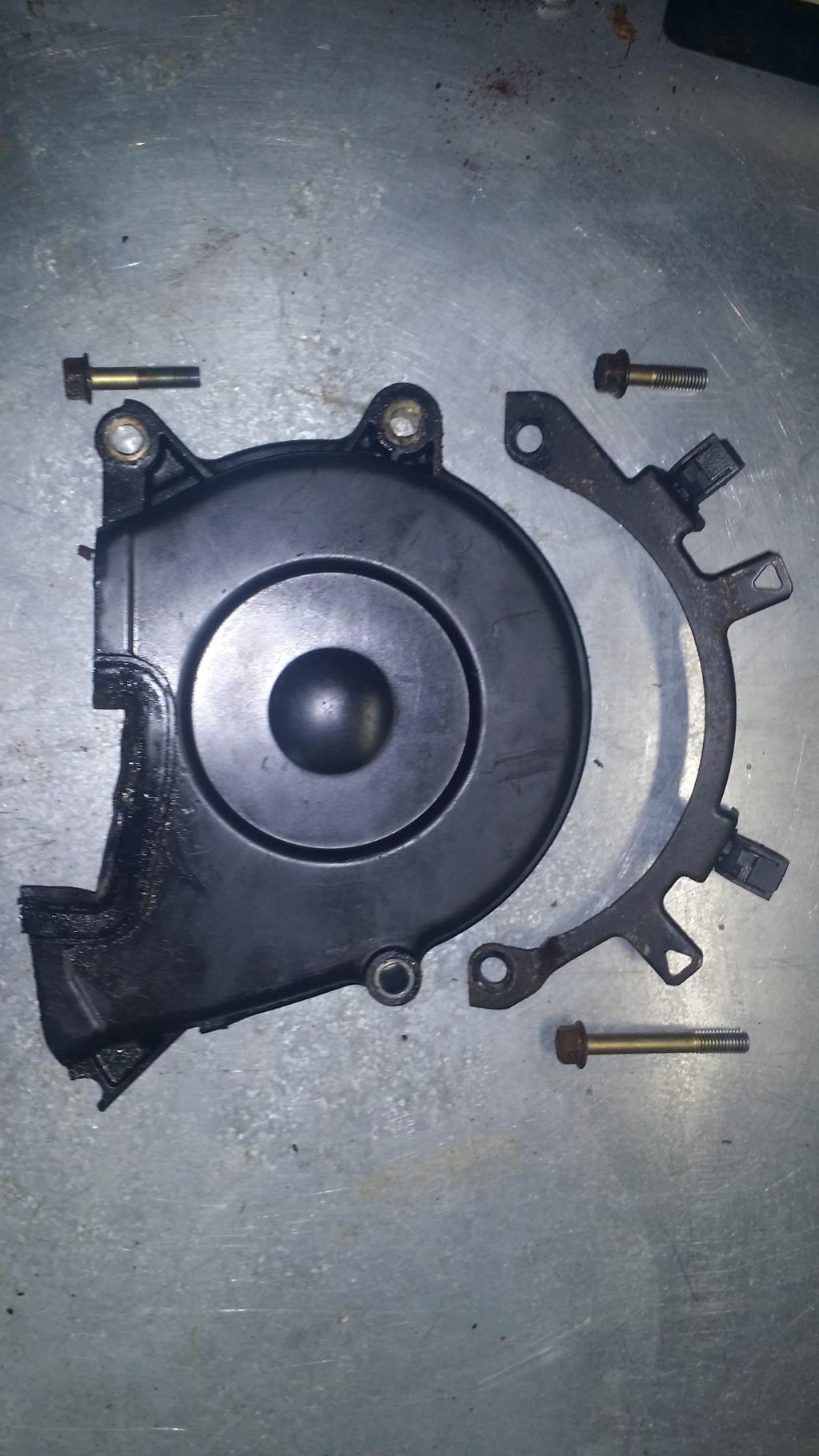
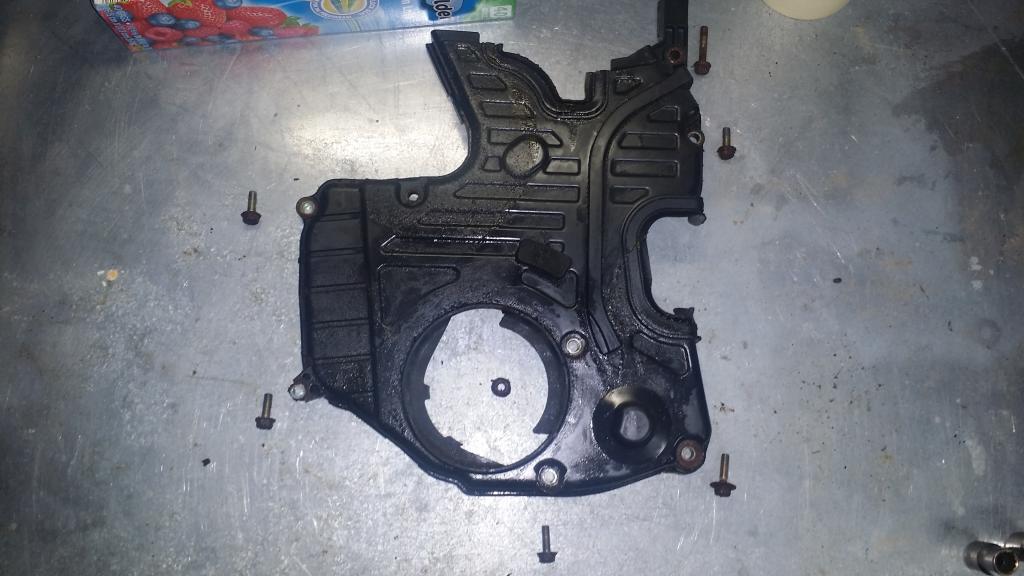
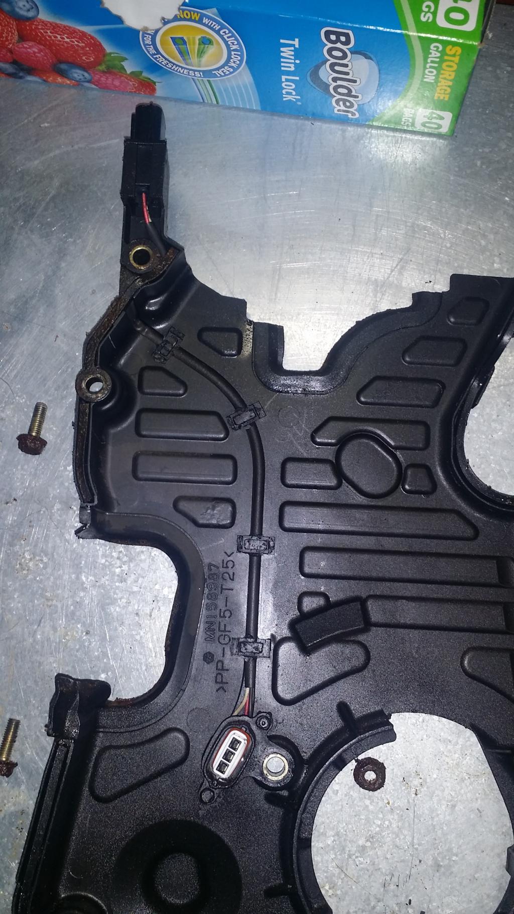
Now we need to remove the lower timing belt cover. It looks like it should be held in place with seven 10mm bolts around the outside of the cover. However I think I might be missing one right under the water pump... there is also a 10mm nut just to the upper right of the crankshaft in the middle of the cover.
So here you can see the top right bolt and the is the longest, the bottom right is slightly longer, then the rest are all the same size. Also if we flip the cover over we can see there is a connector that runs along the inside right down to where the 10mm nut was removed.
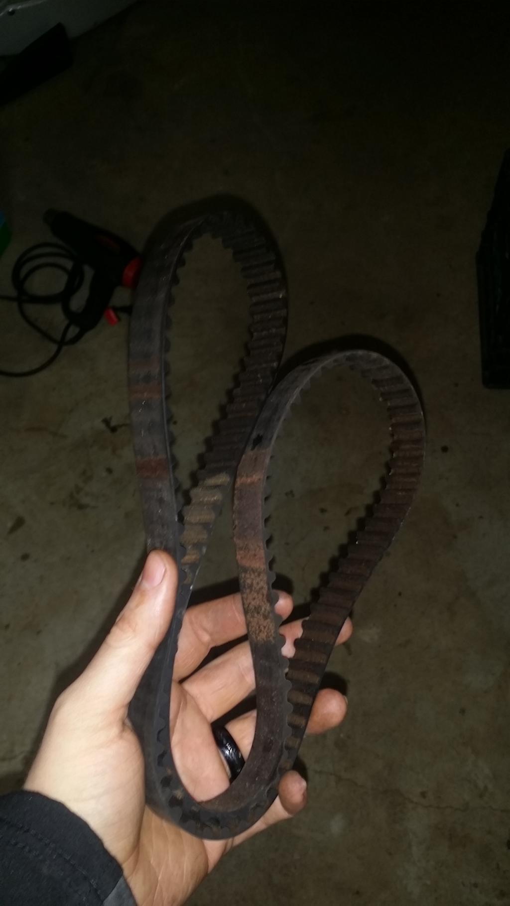
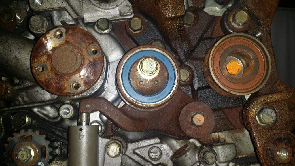
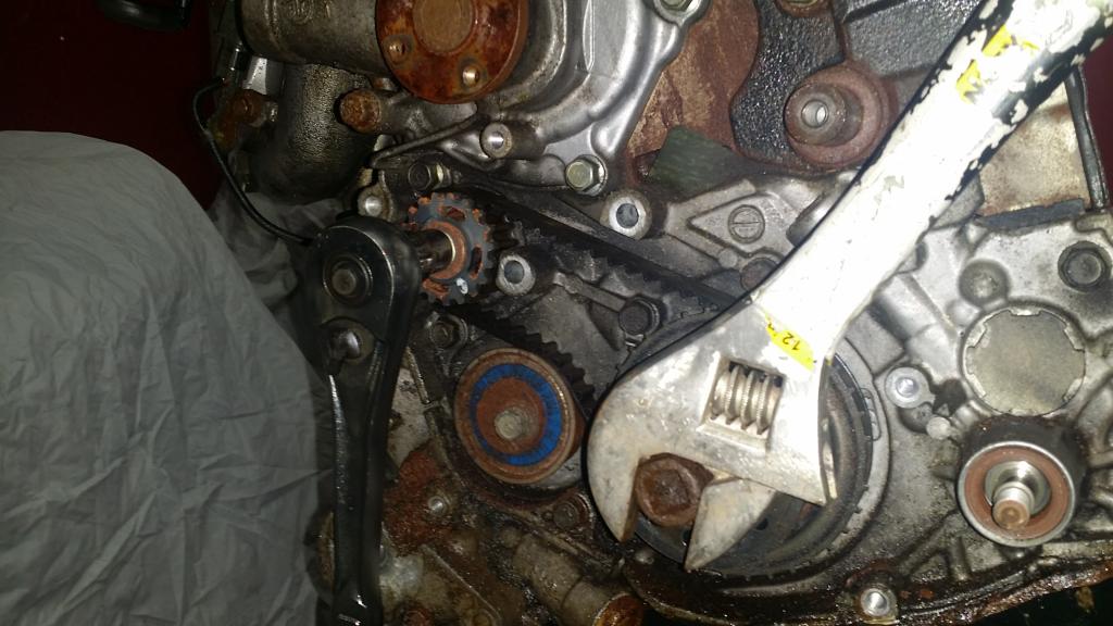
Ok now to remove the timing belt. To do that we need to loosen the tensioner pulley bolt to give the belt some slack. The tensioner pulley is the one in the middle with the blue ring on it. To break it loose use a 14mm socket. when it gets loose enough the pulley will rotate back due to the tension being released from the belt. From there I just pulled the belt off of the tensioner pulley and started following it around freeing it from the rest. Viola timing belt. I'll be ditching this one for a new one.
Next up is to remove the tensioner pulley and its arm. To do this there is a 12mm bolt to the right of the pulley we just loosened. Once that bolt is removed it took some prying but the arm came off. I went ahead and removed the tensioner while I was at it.
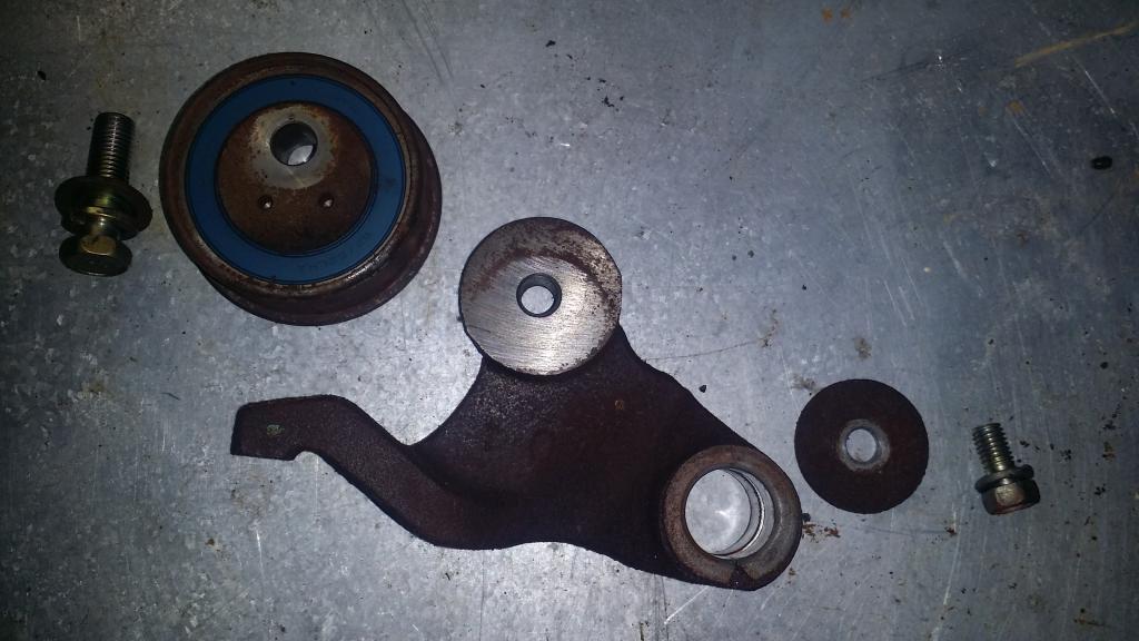
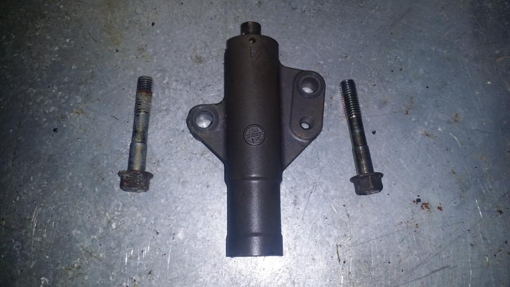
Next up is to remove the auto tensioner. Which you would have noticed by now pushing up on the tensioner arm. It involves removing two 12mm bolts and the auto tensioner just falls off.
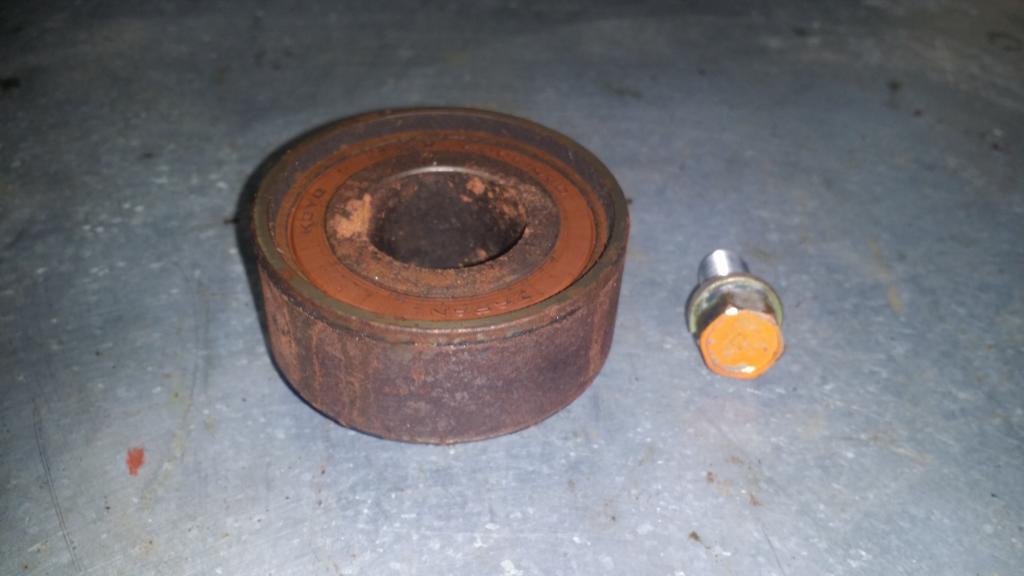
Next up is the idler pulley. In the pic of the tensioner arm and pulley it is the one on the right with the orange bolt. Remove the 14mm bolt in the middle of the pulley then just pluck the pulley from its place. Done.
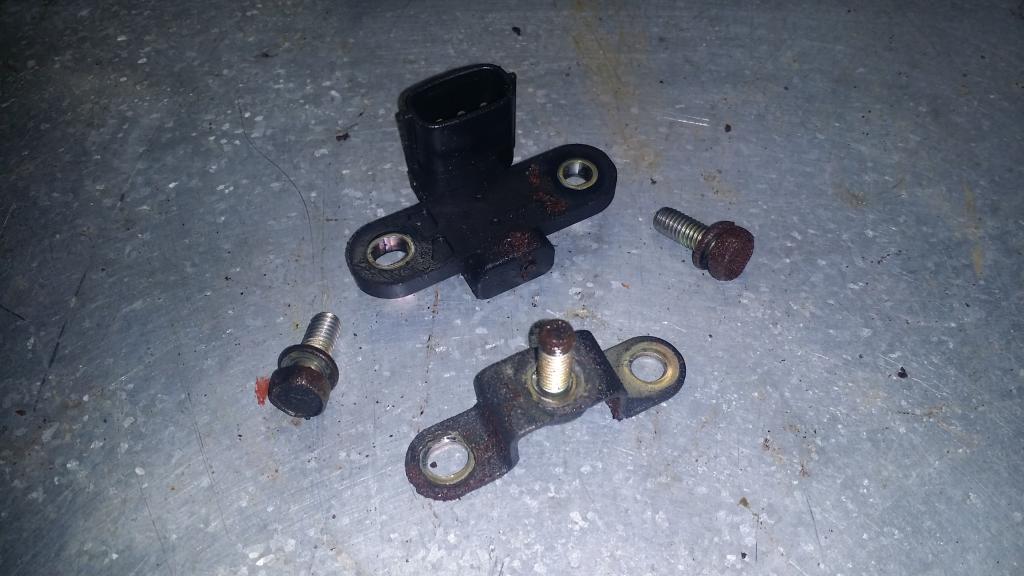
Alright. Rememver the wire I told you about that runs along the inside of the lower cover? Well now its time to remove the sensor it connects to. This is the Crankshaft Position Sensor. Two 10mm bolts and the sensor and bracket fall off.
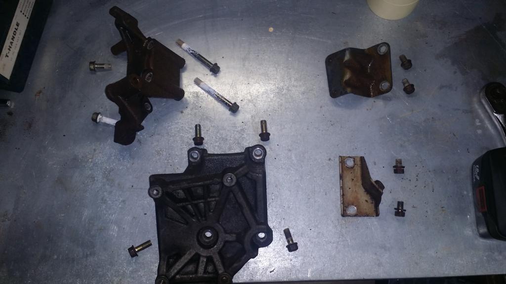
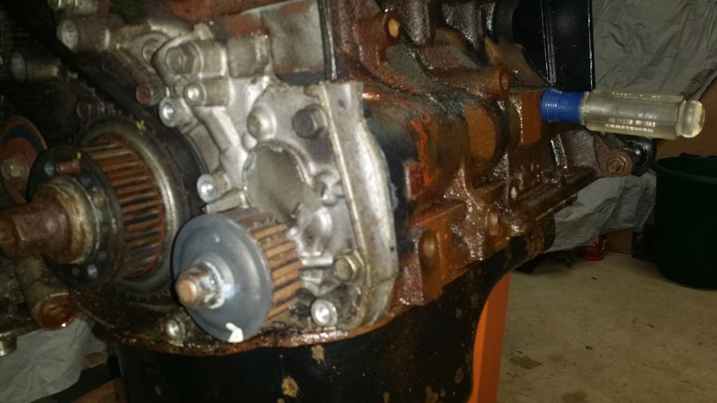
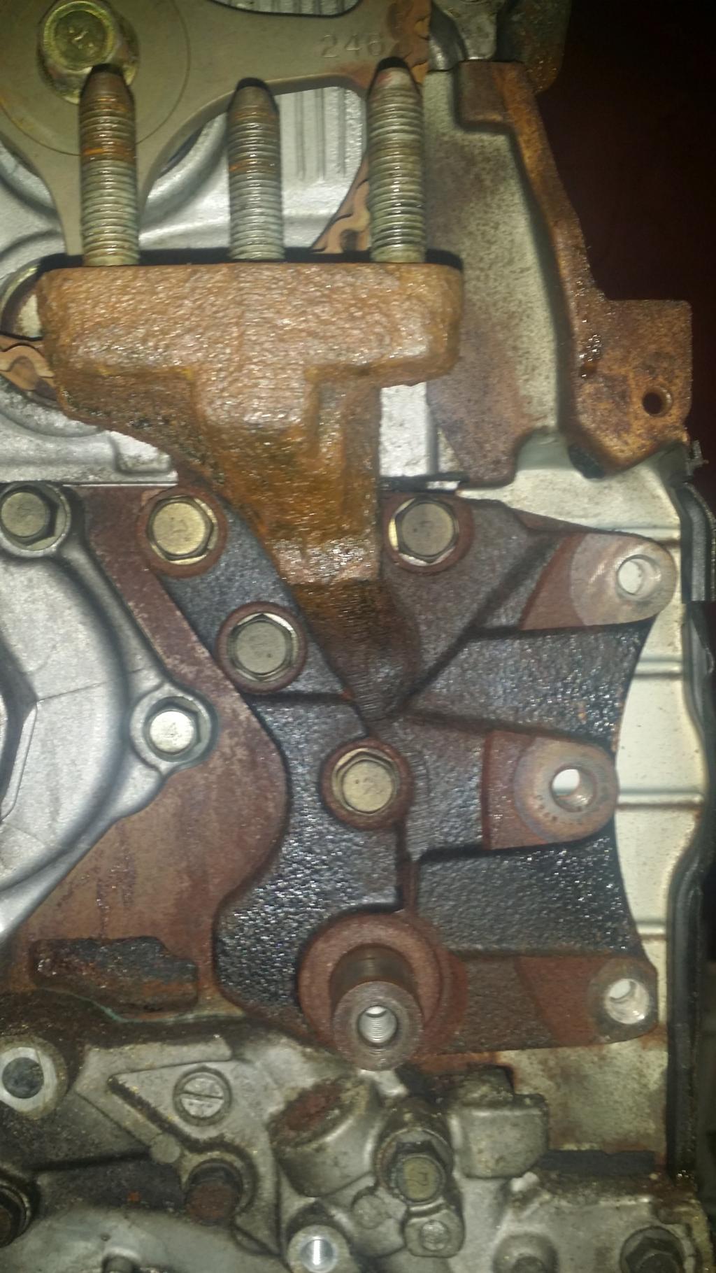
Now we are supposed to remove the Oil Pump Sprocket. However apparently in the FSM they have already removed a few brackets that are still on my engine. Let me do a quick before and after of this.
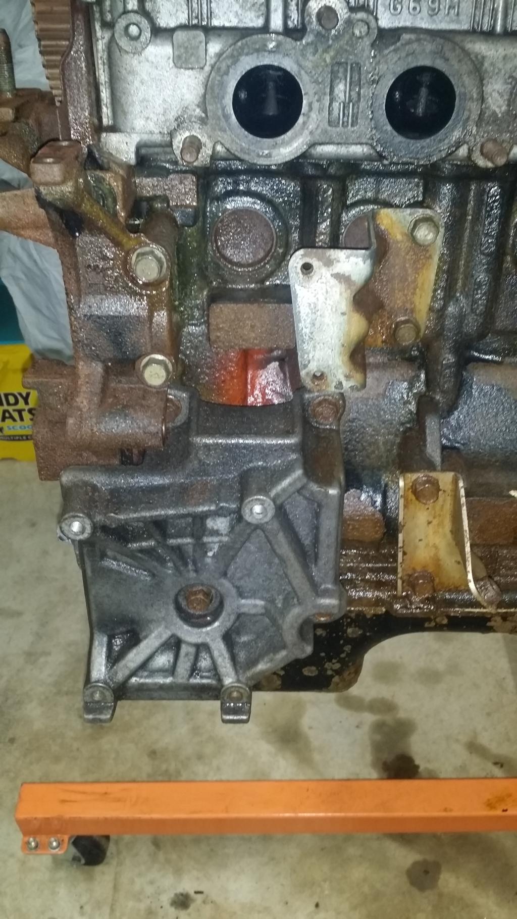
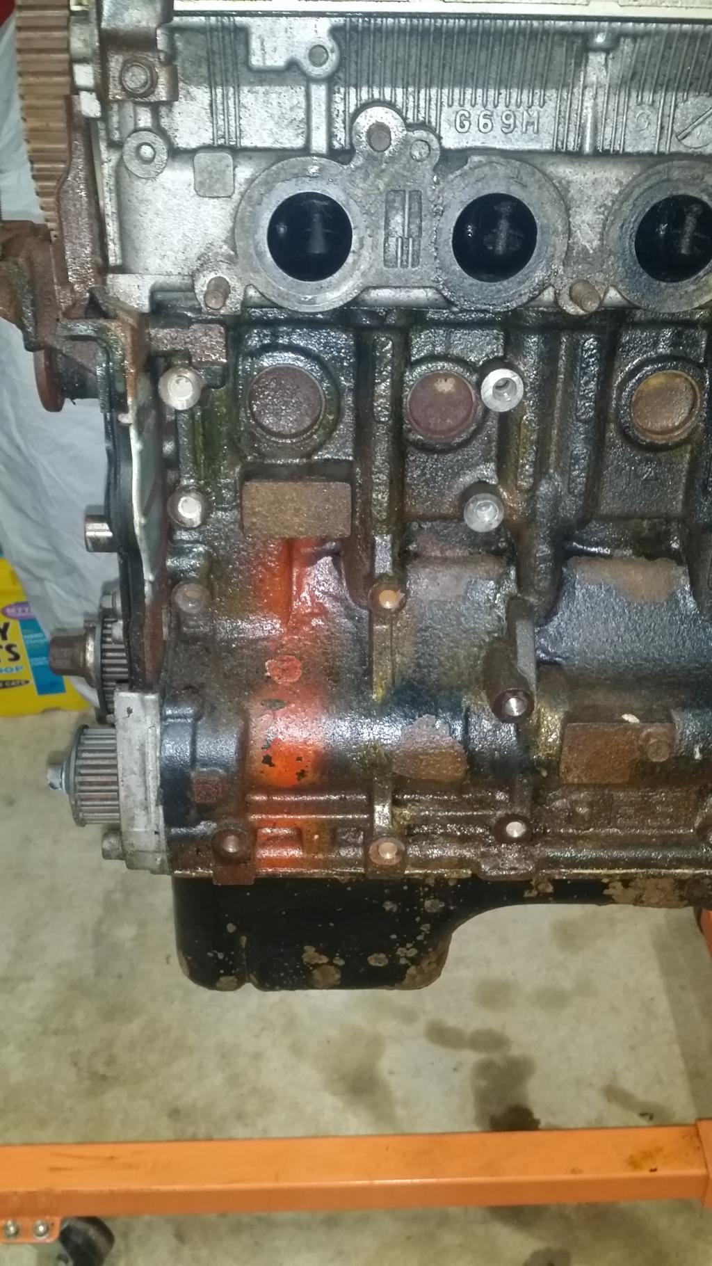
Everything pictured here was removed with a 14mm socket.
Now back to that sprocket. The FSM says to remove a "plug", looks like a 14mm bolt to me... lol
Then it gets very specific about a type of screwdriver that you need to insert into this new hole in the block. "Philips Screwdriver [shank diameter 8mm (0.3 inch)]. Well I wasnt to sure about that so I just eyeballed it.
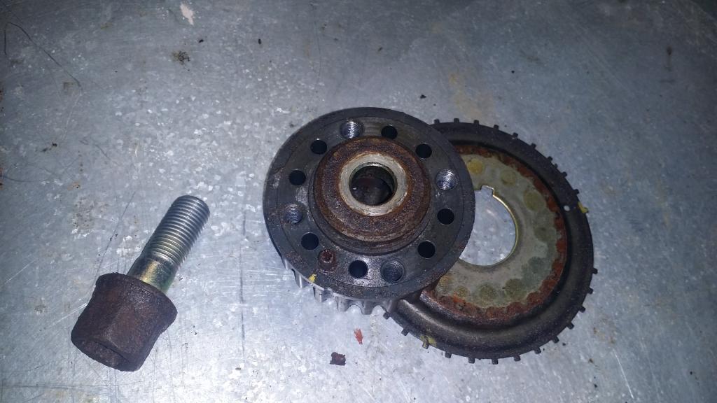
Looks good to me! Moving on! Now we can remove the 14mm nut on the sprocket.
And here is the sprocket, nut, and "plug" we removed. I put the plug back in place after taking this picture.
*somehow lost this picture... sorry*
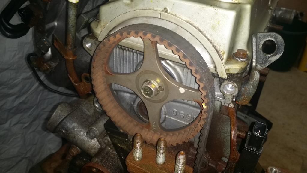
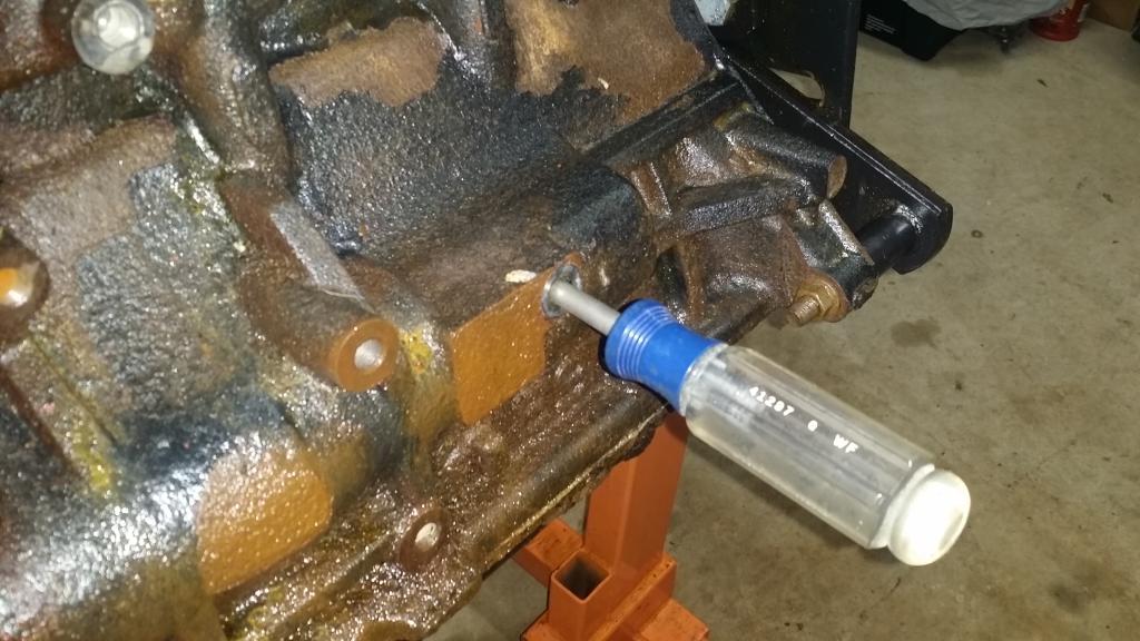
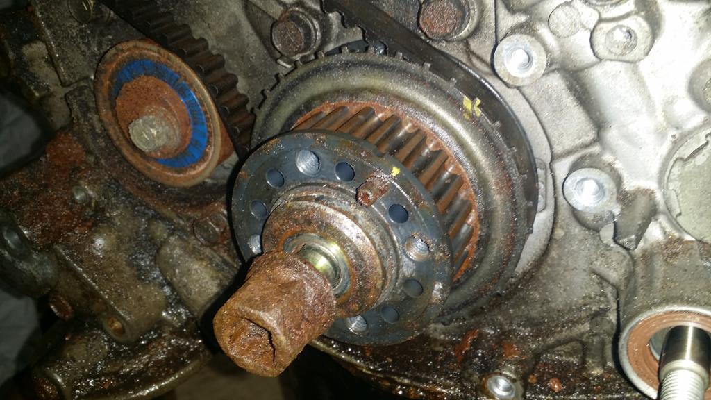
Well we are about halfway through the list of things the FSM says we should remove at this point. And I am planning to remove the oil pump in order to do the balance shaft delete. So now we need to remove the Crankshaft Bolt. This proved interesting. The FSM says you need a special tool to hold the crankshaft still on the flywheel side, wouldnt you know it. I dont have it. But what I do have is a balance shaft timing belt that is still in place. So I put a 12mm socket on it to provide tension against the crankshaft turning. Then I put a big adjustable wrench on the Bolt and put my back into it. It broke loose and I cut my hand on the camshaft sprocket, watchout for that thing if your following along at home. LOL If what I am reading is correct Im going to need this bolt in a few minutes. So Im leaving it in place but loose for now.
Ok, in the FSM the next part involves special tools and is broken down into three parts. I did the simple thing, put the bolt we just removed in far enough that I couldnt see the threads, then pulled the washer, sprocket, and blade all off by hand together. TADA!
Now we can remove the secondary timing belt for the balance shaft on the back of the block.

Same process as last time. Lets remove the tensioner pulley by pulling its 12mm bolt. Then the belt should come off with ease. I went ahead and removed the tiny sprocket here once the belt came off. Again I didnt have the special mitsubishi tool so I improvised. I stuck a screwdriver into one of the 4 holes on the sprocket and used a socket gun with a 12mm socket to remove the bolt holding it and its spacer in place.
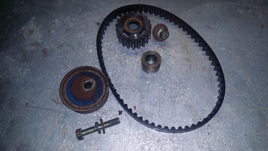
Kinda cute aint it. Like a baby timing belt. Too bad this pulley, this belt, and its sprocket will all be getting trashed... LOL The balance shaft eliminates all of this and some. Removing a point of failure that this tiny belt presents as it is often over looked by mechanics when changine the timing belt on 4Gxx engines. If this little belt snaps it will tie itself up around your crankshaft pulley, get pinched by the main timing belt, which will then skip and bend valves in your head. So say goodbye to the tiny belt!
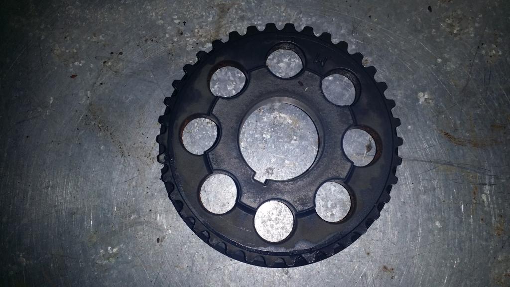
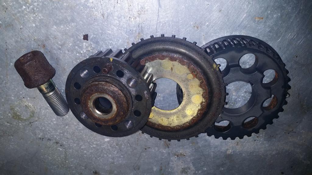
We are going to once again disregard mitsubishi's use of a special tool to remove the sprocket on the crankshaft that spun the balance shaft. Grab that thing and give it a pull. It should come right off!
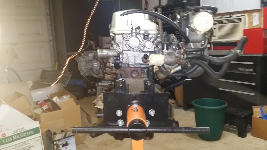
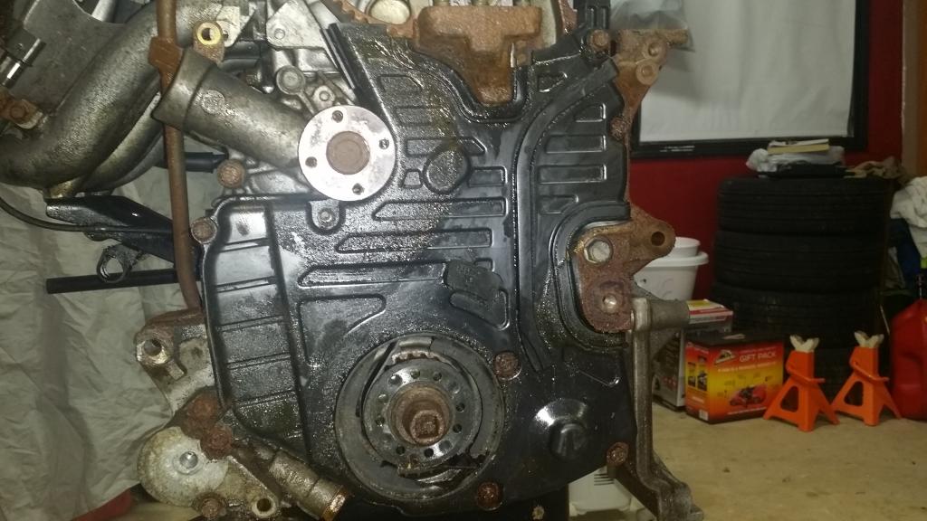
Finally all that is left is the passenger side engine support bracket and the rear timing belt cover. However Im looking at it and not seeing a need to remove it at this time. So Im going to skip it for now and wrap this chapter up. If I need to I'll remove it later looks like 3 bolts 14mm bolts are holding it on so its no big deal.
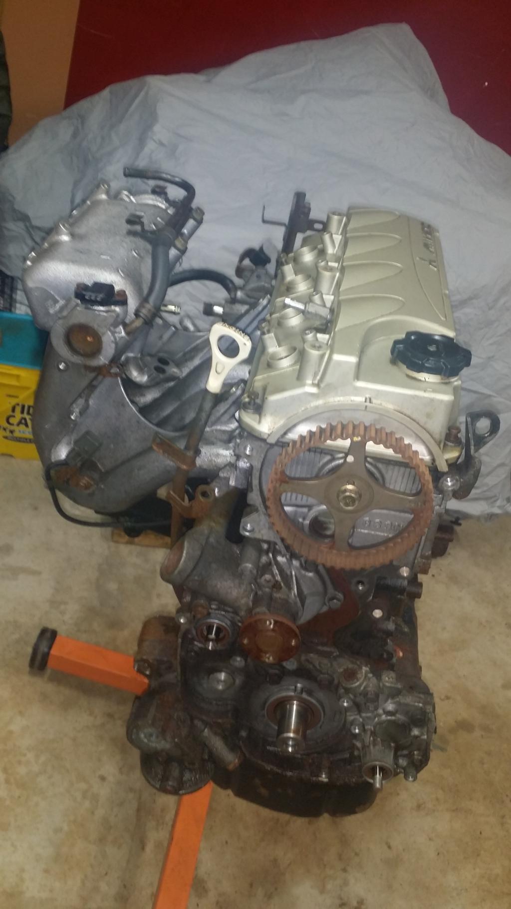
Progress picture!
Next Chapter is the Fuel and Emissions Parts. See you then!
:// Timing Belt Removal
Alright diving right in today. We have a lot of stuff to cover. According to the FSM this is actually Chapter 3. But I already had the exhaust off so I skipped that part. Removing the timing belt and all of its components actually involves 26 parts. Instead of listing them all lets just get started. This one might be longer than I expected.
So starting from here we can see the black timing belt covers. The upper and lower. So we need to start with the upper cover and the metal bracket that holds the wiring harness where it goes over the engine.
This is a very simple process. The cover and bracket are only held on with three 12mm bolts. Remember the one on the front side is the long one.
Interestingly enough I expected to find the timing belt broken, shredded, or tucked down in the lower cover. But its not. It doesnt even have much play. Im actually beginning to wonder if I was told the right story about this car having bent valves because a bad tensioner caused the timing to skip... Well we will see when we get there. Moving on!
Now we need to remove the lower timing belt cover. It looks like it should be held in place with seven 10mm bolts around the outside of the cover. However I think I might be missing one right under the water pump... there is also a 10mm nut just to the upper right of the crankshaft in the middle of the cover.
So here you can see the top right bolt and the is the longest, the bottom right is slightly longer, then the rest are all the same size. Also if we flip the cover over we can see there is a connector that runs along the inside right down to where the 10mm nut was removed.
Ok now to remove the timing belt. To do that we need to loosen the tensioner pulley bolt to give the belt some slack. The tensioner pulley is the one in the middle with the blue ring on it. To break it loose use a 14mm socket. when it gets loose enough the pulley will rotate back due to the tension being released from the belt. From there I just pulled the belt off of the tensioner pulley and started following it around freeing it from the rest. Viola timing belt. I'll be ditching this one for a new one.
Next up is to remove the tensioner pulley and its arm. To do this there is a 12mm bolt to the right of the pulley we just loosened. Once that bolt is removed it took some prying but the arm came off. I went ahead and removed the tensioner while I was at it.
Next up is to remove the auto tensioner. Which you would have noticed by now pushing up on the tensioner arm. It involves removing two 12mm bolts and the auto tensioner just falls off.
Next up is the idler pulley. In the pic of the tensioner arm and pulley it is the one on the right with the orange bolt. Remove the 14mm bolt in the middle of the pulley then just pluck the pulley from its place. Done.
Alright. Rememver the wire I told you about that runs along the inside of the lower cover? Well now its time to remove the sensor it connects to. This is the Crankshaft Position Sensor. Two 10mm bolts and the sensor and bracket fall off.
Now we are supposed to remove the Oil Pump Sprocket. However apparently in the FSM they have already removed a few brackets that are still on my engine. Let me do a quick before and after of this.
Everything pictured here was removed with a 14mm socket.
Now back to that sprocket. The FSM says to remove a "plug", looks like a 14mm bolt to me... lol
Then it gets very specific about a type of screwdriver that you need to insert into this new hole in the block. "Philips Screwdriver [shank diameter 8mm (0.3 inch)]. Well I wasnt to sure about that so I just eyeballed it.
Looks good to me! Moving on! Now we can remove the 14mm nut on the sprocket.
And here is the sprocket, nut, and "plug" we removed. I put the plug back in place after taking this picture.
*somehow lost this picture... sorry*
Well we are about halfway through the list of things the FSM says we should remove at this point. And I am planning to remove the oil pump in order to do the balance shaft delete. So now we need to remove the Crankshaft Bolt. This proved interesting. The FSM says you need a special tool to hold the crankshaft still on the flywheel side, wouldnt you know it. I dont have it. But what I do have is a balance shaft timing belt that is still in place. So I put a 12mm socket on it to provide tension against the crankshaft turning. Then I put a big adjustable wrench on the Bolt and put my back into it. It broke loose and I cut my hand on the camshaft sprocket, watchout for that thing if your following along at home. LOL If what I am reading is correct Im going to need this bolt in a few minutes. So Im leaving it in place but loose for now.
Ok, in the FSM the next part involves special tools and is broken down into three parts. I did the simple thing, put the bolt we just removed in far enough that I couldnt see the threads, then pulled the washer, sprocket, and blade all off by hand together. TADA!
Now we can remove the secondary timing belt for the balance shaft on the back of the block.
Same process as last time. Lets remove the tensioner pulley by pulling its 12mm bolt. Then the belt should come off with ease. I went ahead and removed the tiny sprocket here once the belt came off. Again I didnt have the special mitsubishi tool so I improvised. I stuck a screwdriver into one of the 4 holes on the sprocket and used a socket gun with a 12mm socket to remove the bolt holding it and its spacer in place.
Kinda cute aint it. Like a baby timing belt. Too bad this pulley, this belt, and its sprocket will all be getting trashed... LOL The balance shaft eliminates all of this and some. Removing a point of failure that this tiny belt presents as it is often over looked by mechanics when changine the timing belt on 4Gxx engines. If this little belt snaps it will tie itself up around your crankshaft pulley, get pinched by the main timing belt, which will then skip and bend valves in your head. So say goodbye to the tiny belt!
We are going to once again disregard mitsubishi's use of a special tool to remove the sprocket on the crankshaft that spun the balance shaft. Grab that thing and give it a pull. It should come right off!
Finally all that is left is the passenger side engine support bracket and the rear timing belt cover. However Im looking at it and not seeing a need to remove it at this time. So Im going to skip it for now and wrap this chapter up. If I need to I'll remove it later looks like 3 bolts 14mm bolts are holding it on so its no big deal.
Progress picture!
Next Chapter is the Fuel and Emissions Parts. See you then!
Last edited by bakuro117; Jan 30, 2015 at 05:48 AM.
The following users liked this post:
mbsuity (Aug 21, 2018)
Trending Topics
Jan 29, 2015, 11:44 AM
#9
Thanks for all the positive feedback guys! I really appreciate it. It makes doing this worth it. Plus Ive found that when I have to stop and write every so often it makes me stay organized and patient. Normally I'd have tools everywhere, parts everywhere, and be in a mess already but Ive stayed really on point so far. Im going to try to keep the ball rolling tonight, hopefully I can get the fuel and intake manifold taken care of. However I just remembered that my wife is off tonight and tomorrow so I might have to break that into two parts afterall. That or just wait until its all done before posting again... IDK we'll see. LOL
Thanks again!!
Thanks again!!
Jan 30, 2015, 05:45 AM
#10
>: CHAPTER 3 :<
:// Fuel and Emission Parts
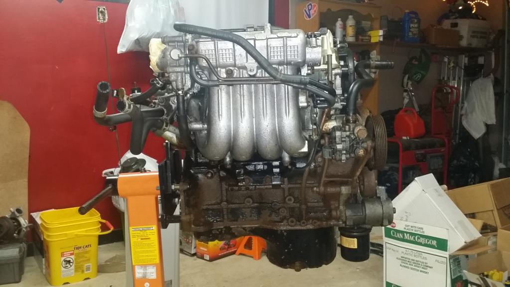
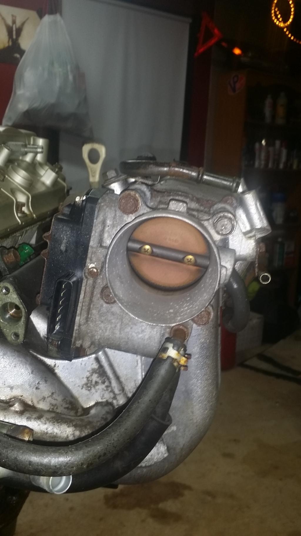
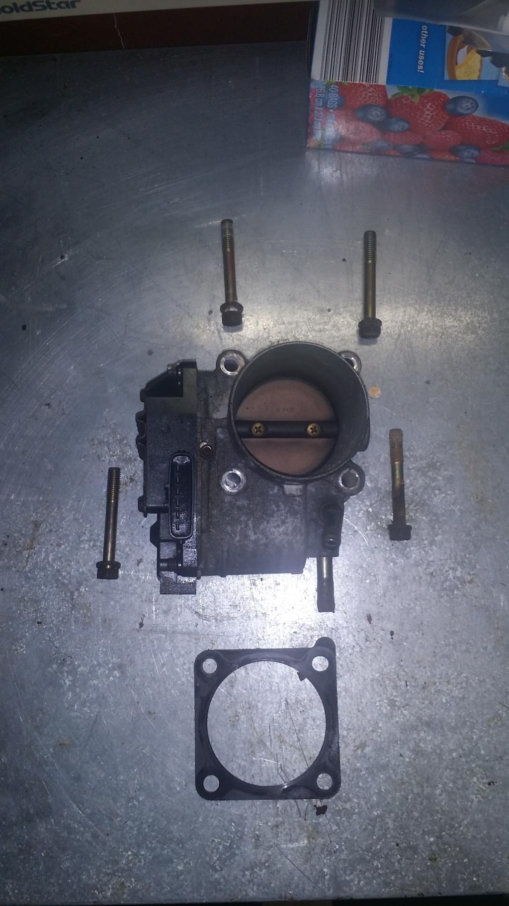
Decided to break chapter 3 into the two parts it should have been instead of another massive chapter. We are going to be removing the Fuel and Emissions Parts as according to the FSM. This involves the Throttle Body, a few Vacuum lines, Injectors, Fuel Rail, Exhaust Gas Recirculation Valve, and a Solenoid Valve.
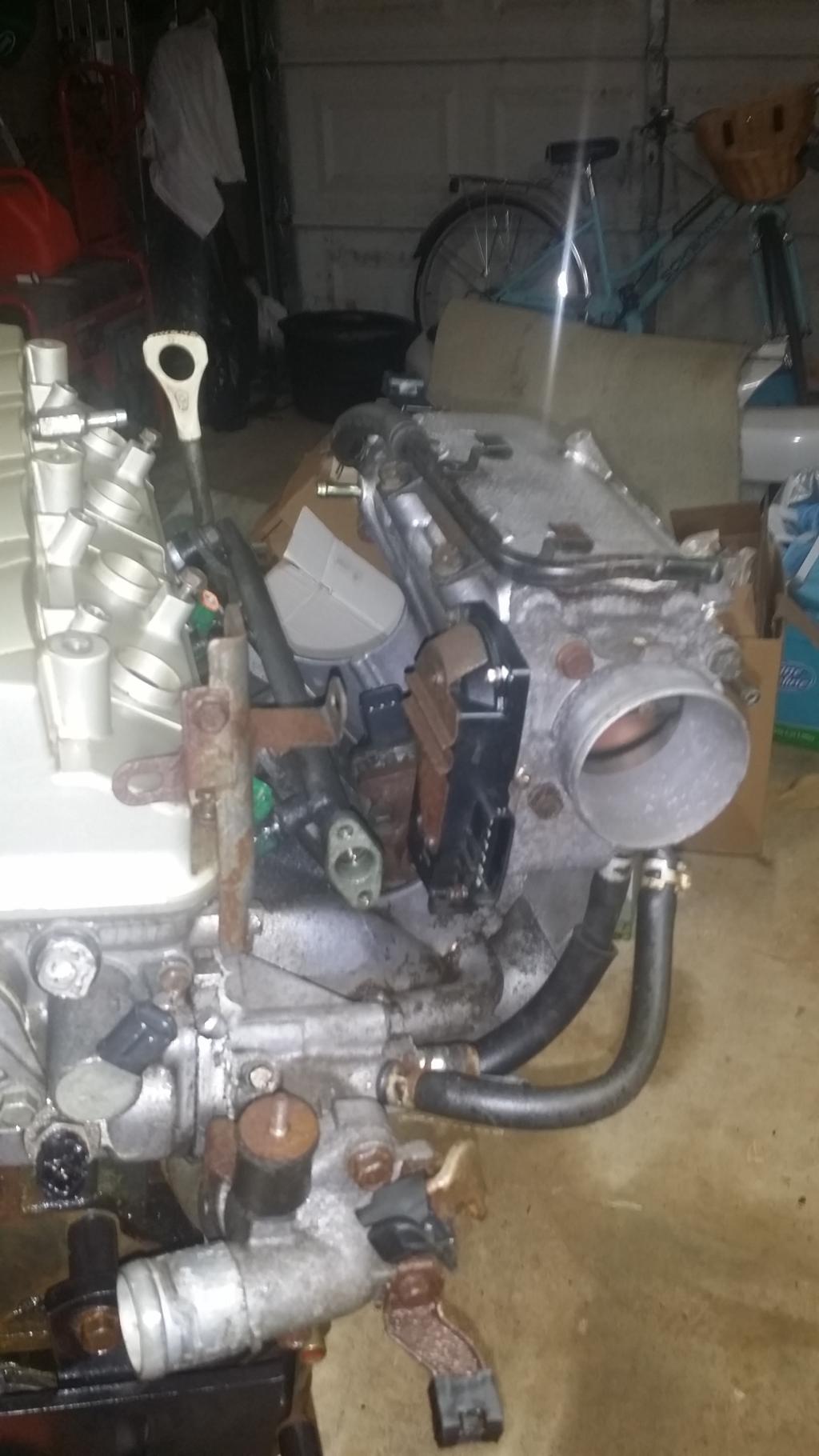
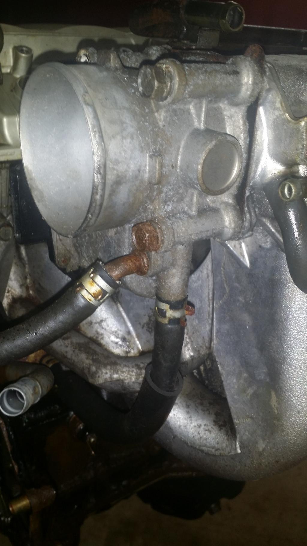
We will start with the Throttle Body. You can see from the pic there are four 12mm bolts holding it onto the Intake Manifold. There are also 2 coolant lines that attach to the bottom on the back side. If you grab them with some plyers and twist it will break the hose loose and it will come off much easier. Remove the hoses and bolts and the TB and its gasket will come right off. Remember if you are installing a TB gasket they can sometimes be real picky about their orientation. In this case the tab goes up and on the top rear bolt hole. The picture on the bench shows the orientation.
Next up is the Vacuum Line and Hose. I'm also going to leave the Solenoid valve attached and remove them all as one piece. To do this you need to remove five 10mm bolts, make sure the hoses are no longer attached, and it should fall right off.
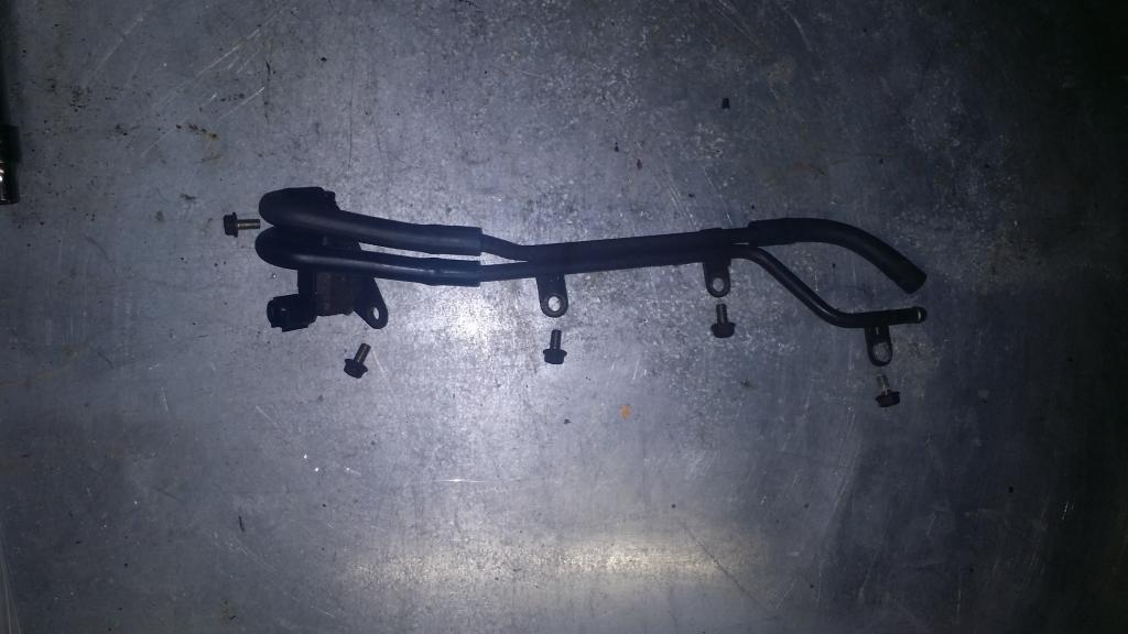
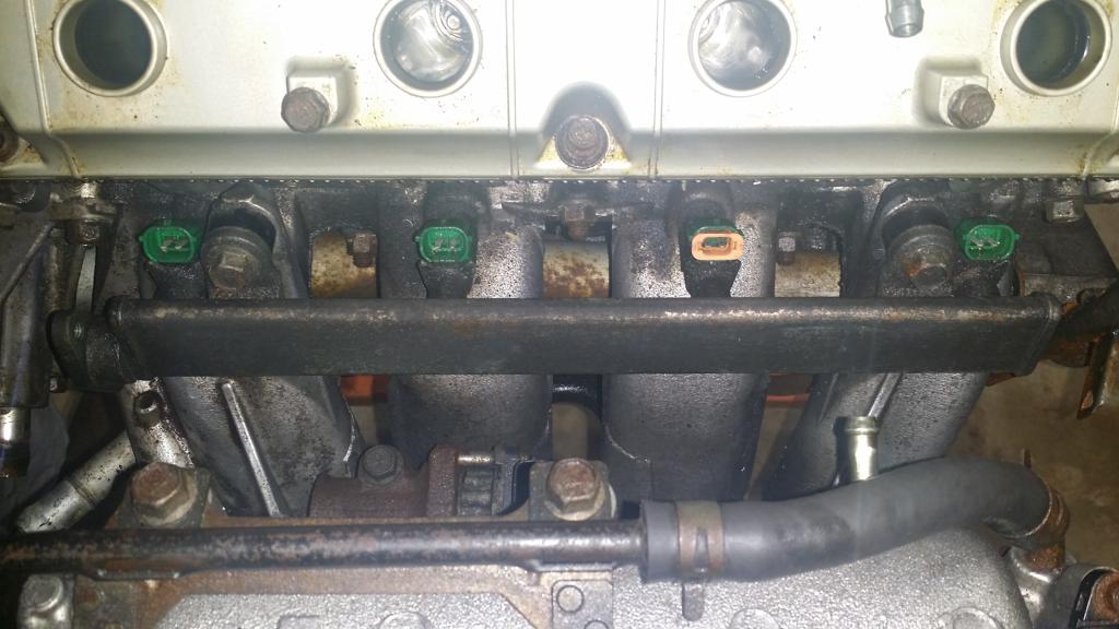
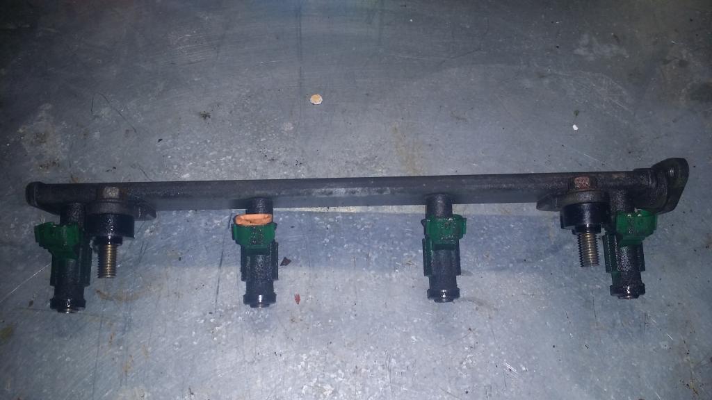
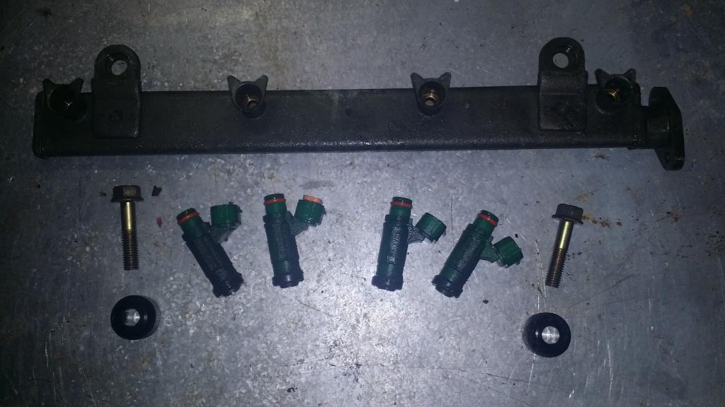
Now let’s go on to the fuel rail. With everything else removed you should be able to reach two 12mm bolts holding the fuel rail in place quite easily. Be careful when removing the rail because all the injectors, their O rings and the spacers for the rail will want to come off at once. Make sure that all injectors have their O rings and none are left in the intake manifold. If you need to remove the injectors from the rail, wiggle them slowly while pulling and they will eventually pop out. The end of the injectors that sits inside the fuel rail also has an orange O ring so make sure not to lose those.
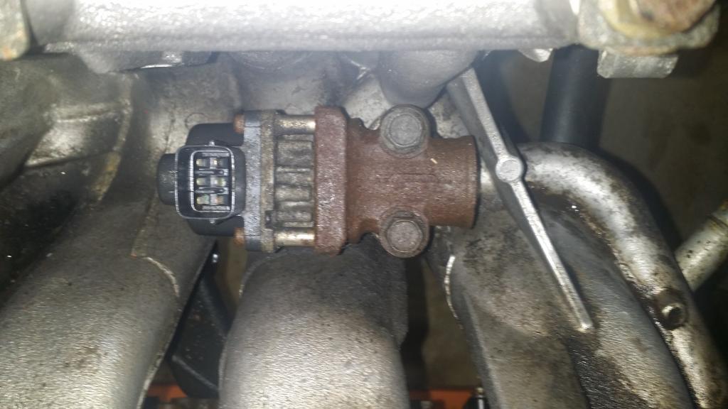
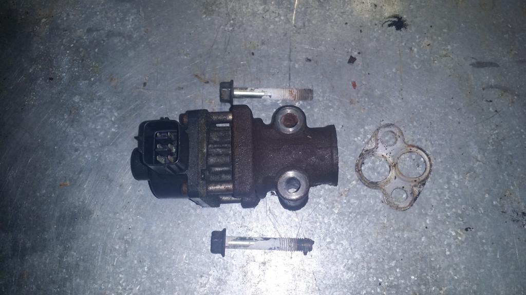
The final step in this chapter is to remove the exhaust gas recirculation valve. This too is held on with two 12mm bolts. You'll want to use a long extension to reach the bolt closest to the plentum, or you could squeeze a tiny socket down in there. Once the bolts are removed, just lift the valve out, the gasket will probably come with it. The FSM specifies a direction for the gasket -see picture for orientation-
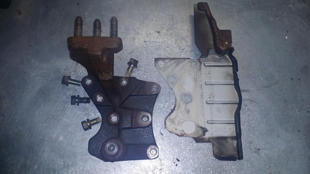
That concludes this chapter, but I changed my mind about removing the engine support bracket from the end of Chapter 2. To do so remove the four 14mm bolts holding it the engine, you may have to put some muscle into it. Remember that the upper right bolt is slightly longer than the rest. Apparently sandwiched between the bracket and the block is the rear timing belt cover so it will come off at the same time.
That’s all she wrote for tonight. Literally. This chapter was written by Josh's wonderful wife while he did all the manual labor.
XOXO
-Christeen
Next time we'll cover the Intake Manifold and Water Pump.
:// Fuel and Emission Parts
Decided to break chapter 3 into the two parts it should have been instead of another massive chapter. We are going to be removing the Fuel and Emissions Parts as according to the FSM. This involves the Throttle Body, a few Vacuum lines, Injectors, Fuel Rail, Exhaust Gas Recirculation Valve, and a Solenoid Valve.
We will start with the Throttle Body. You can see from the pic there are four 12mm bolts holding it onto the Intake Manifold. There are also 2 coolant lines that attach to the bottom on the back side. If you grab them with some plyers and twist it will break the hose loose and it will come off much easier. Remove the hoses and bolts and the TB and its gasket will come right off. Remember if you are installing a TB gasket they can sometimes be real picky about their orientation. In this case the tab goes up and on the top rear bolt hole. The picture on the bench shows the orientation.
Next up is the Vacuum Line and Hose. I'm also going to leave the Solenoid valve attached and remove them all as one piece. To do this you need to remove five 10mm bolts, make sure the hoses are no longer attached, and it should fall right off.
Now let’s go on to the fuel rail. With everything else removed you should be able to reach two 12mm bolts holding the fuel rail in place quite easily. Be careful when removing the rail because all the injectors, their O rings and the spacers for the rail will want to come off at once. Make sure that all injectors have their O rings and none are left in the intake manifold. If you need to remove the injectors from the rail, wiggle them slowly while pulling and they will eventually pop out. The end of the injectors that sits inside the fuel rail also has an orange O ring so make sure not to lose those.
The final step in this chapter is to remove the exhaust gas recirculation valve. This too is held on with two 12mm bolts. You'll want to use a long extension to reach the bolt closest to the plentum, or you could squeeze a tiny socket down in there. Once the bolts are removed, just lift the valve out, the gasket will probably come with it. The FSM specifies a direction for the gasket -see picture for orientation-
That concludes this chapter, but I changed my mind about removing the engine support bracket from the end of Chapter 2. To do so remove the four 14mm bolts holding it the engine, you may have to put some muscle into it. Remember that the upper right bolt is slightly longer than the rest. Apparently sandwiched between the bracket and the block is the rear timing belt cover so it will come off at the same time.
That’s all she wrote for tonight. Literally. This chapter was written by Josh's wonderful wife while he did all the manual labor.
XOXO
-Christeen
Next time we'll cover the Intake Manifold and Water Pump.
Last edited by bakuro117; Jan 30, 2015 at 05:49 AM.
Jan 31, 2015, 05:22 PM
#12
>: CHAPTER 4 :<
Intake Manifold and Water Pump
Removing the manifold and pump involves quite a few parts. Hoses, Pump, Gaskets, O-rings, Pipes, Supports, Gauges, Fittings, Thermostat, Housings, Sensors, the Manifold, and Switches. But we'll probably get through this one pretty quick.
First order of business. Remember those hoses we removed from the Throttle Body? Let�s get those off first. You probably know the routine for these guys by now.
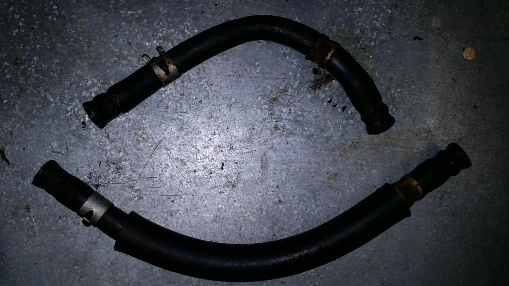
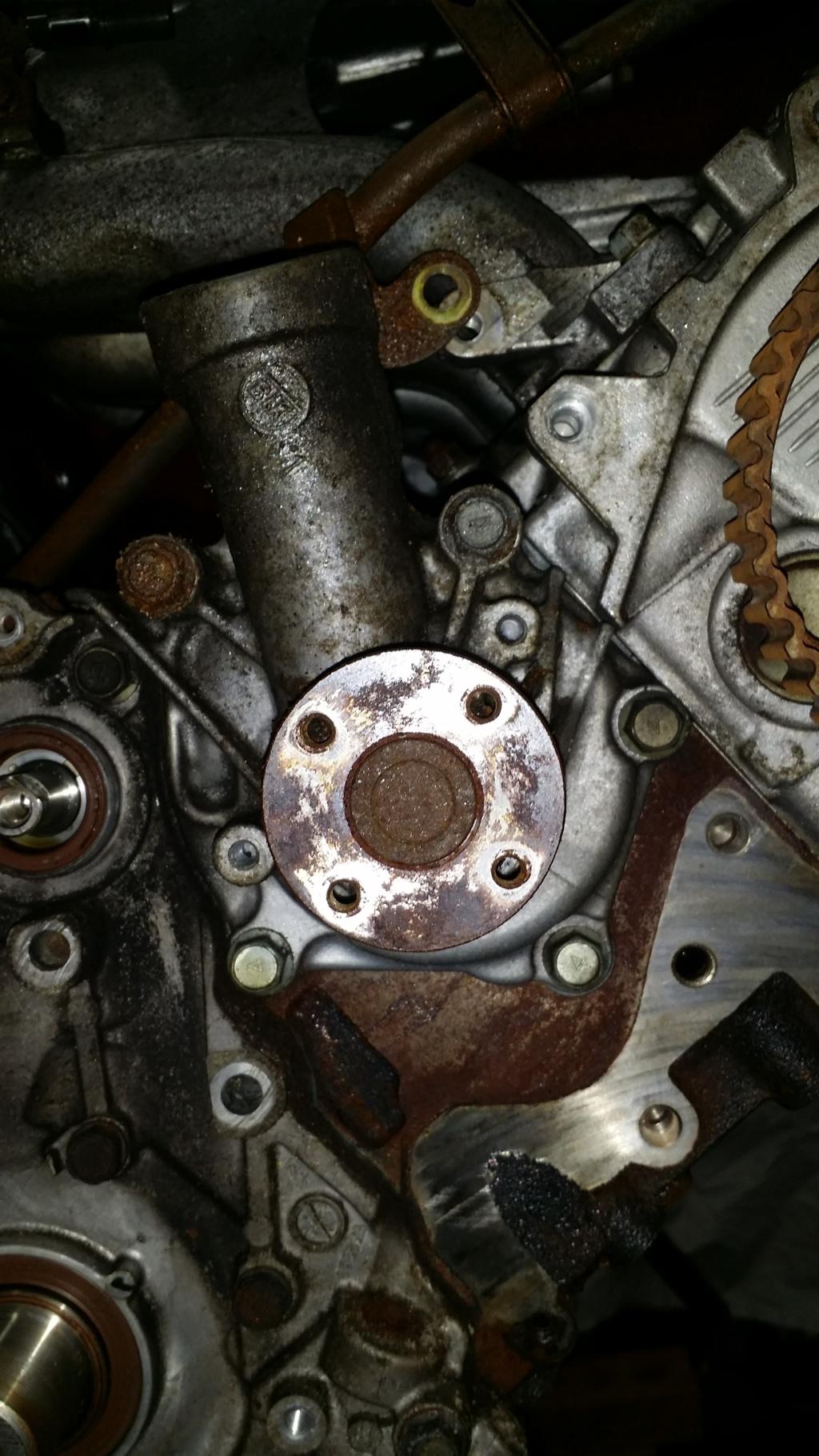
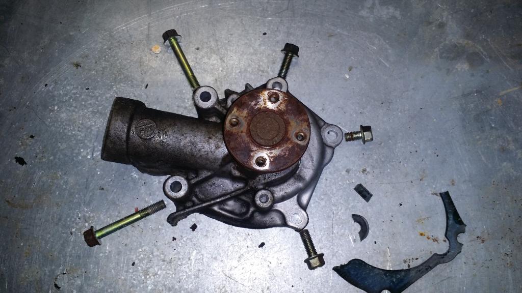
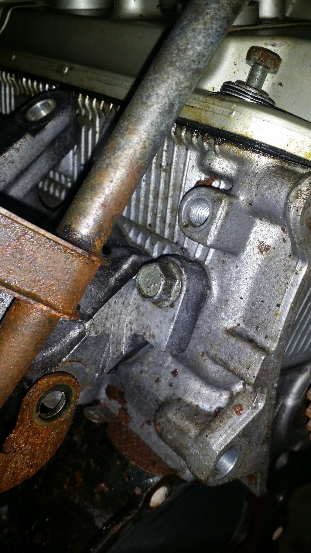
Now we go straight for the Water Pump and its gasket. To do so remove the five 12mm bolts holding it in place. I had to wrestle with it a bit to get it off of the water pipe, but it eventually let go. The gasket however split, half on the pump, and half on the block. I had to scrap the pieces off the block. Also there are 3 different bolt lengths please refer to the bench picture on where they go.
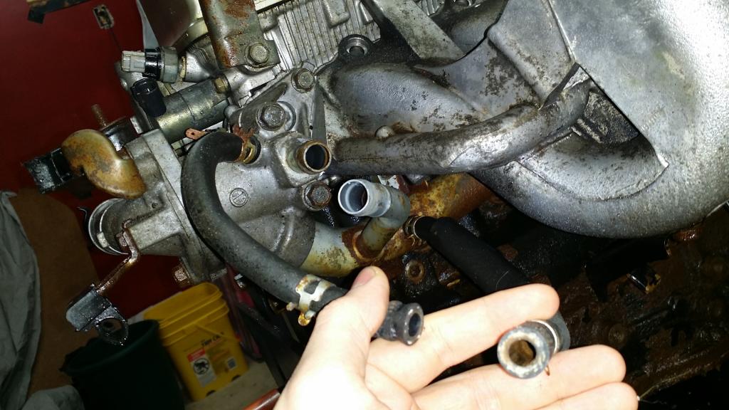
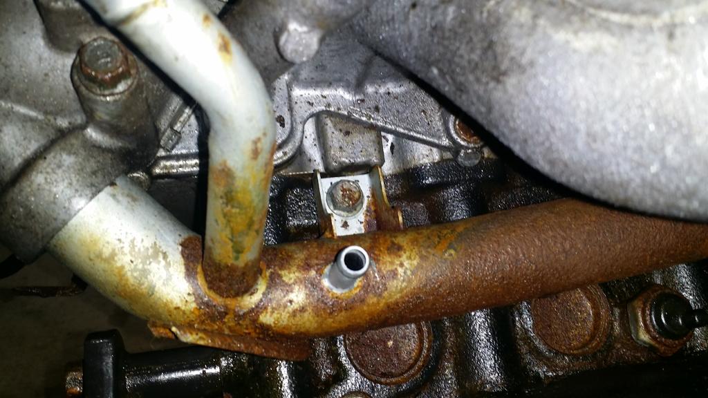
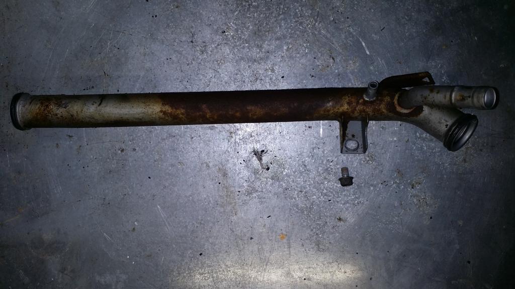
With that done we can go ahead and remove the Water Pipe. This is only held in place with a single 12mm bolt, I used a long extension to reach it. Takes some wiggling but the O-ring in the Thermostat housing will eventually come loose.
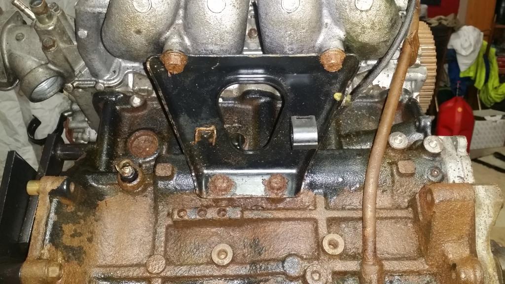
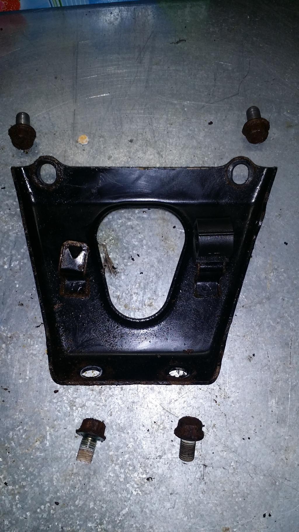
Next is the Intake Manifold Support. Four 14mm bolts hold this in place. There is also a small plastic clip that supports the wire for the Knock sensor. Pinch it form the inside with some needle nose pliers then pull it free from the wire side.
The next parts we will remove will be the Engine Coolant Temperature Gauge Unit, The Water Inlet Fitting, Thermostat, and Thermostat Housing.
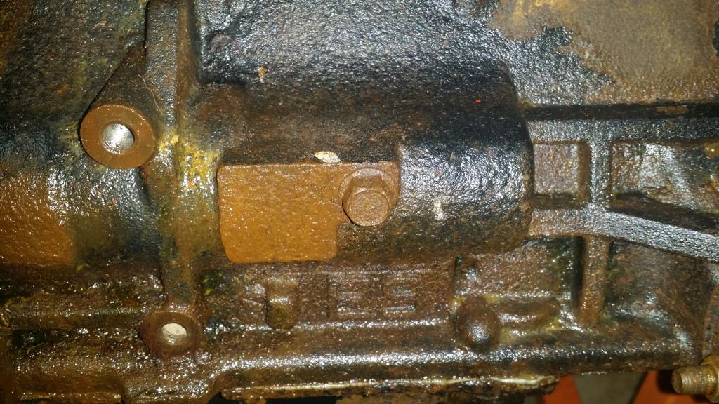
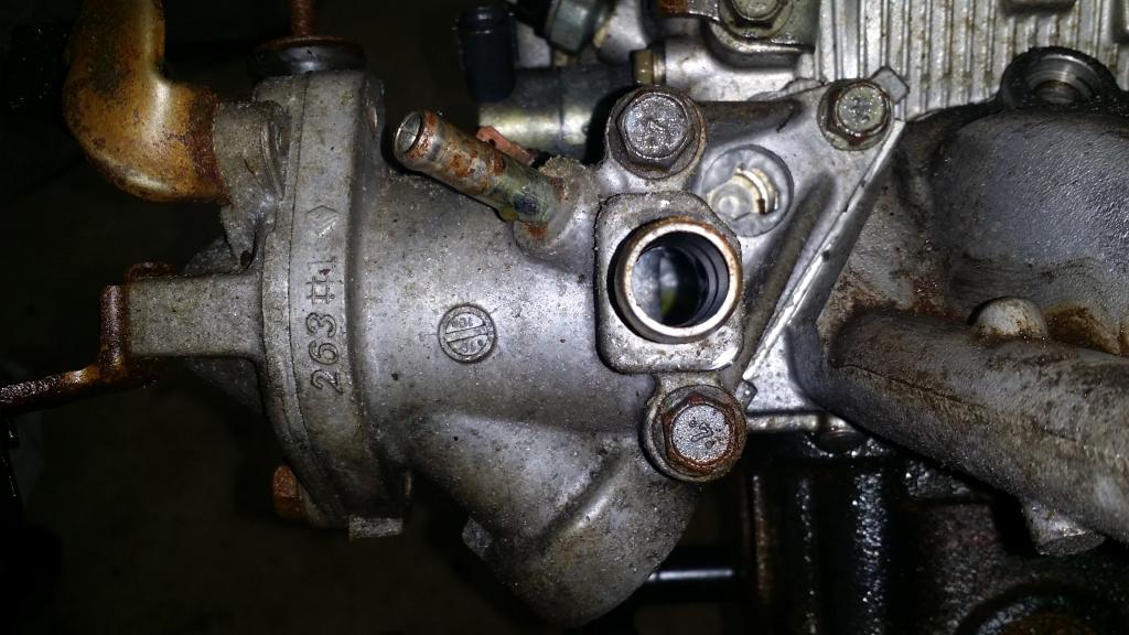
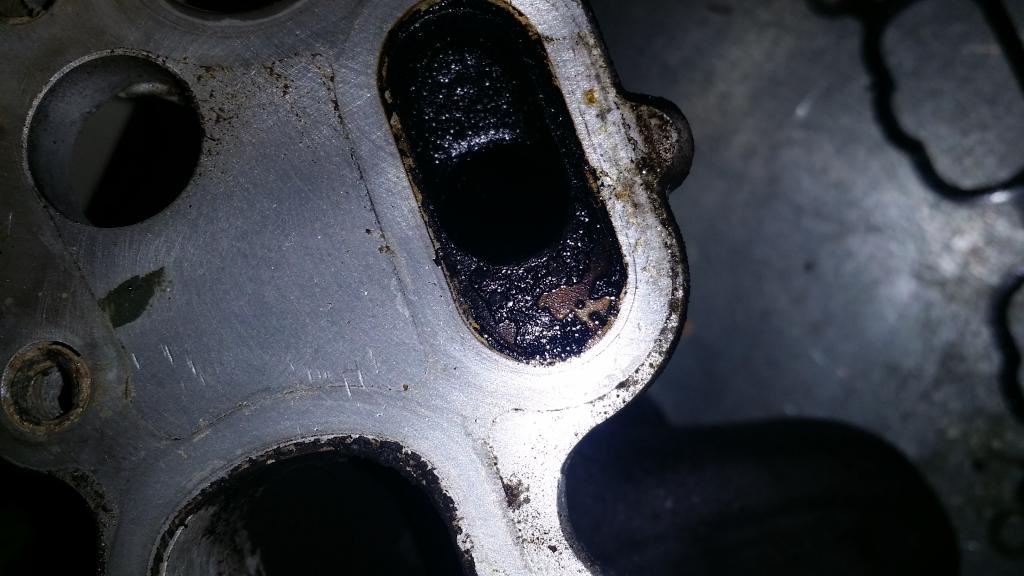
Instead of breaking this down I think I will just remove them all together. To do so we will just remove the Thermostat Housing and everything will come with it. The Housing is held in place with three 12mm bolts. There was a lot of RTV holding it on, so I convinced it do come off with a rubber hammer. BTW in the first pic does anyone know what that hole with all the RTV is supposed to be? It goes on into the head and I don�t remember removing anything from there...
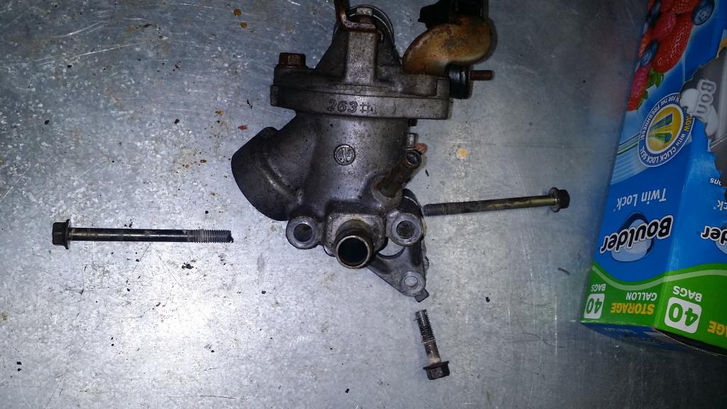
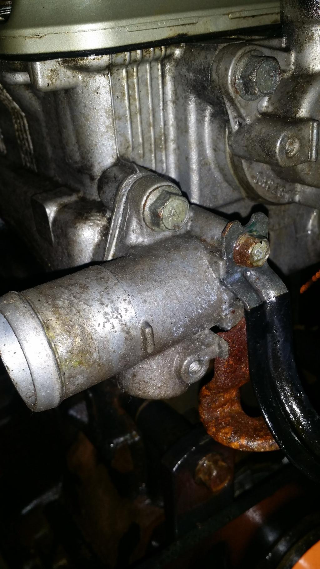
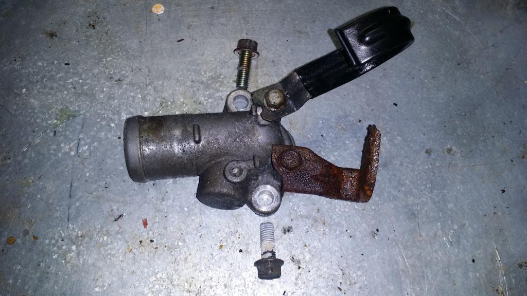
I�m going to skip ahead a bit here and go ahead and remove the Water Outlet Fitting. I had to loosen a couple of brackets attached to this piece so that I could get to the bolt on the bottom. The two brackets use a 10mm bolt each, and the Fitting uses two 12mm bolts. Again there is a lot of RTV on this piece, I used my trusty rubber mallet to remove it.
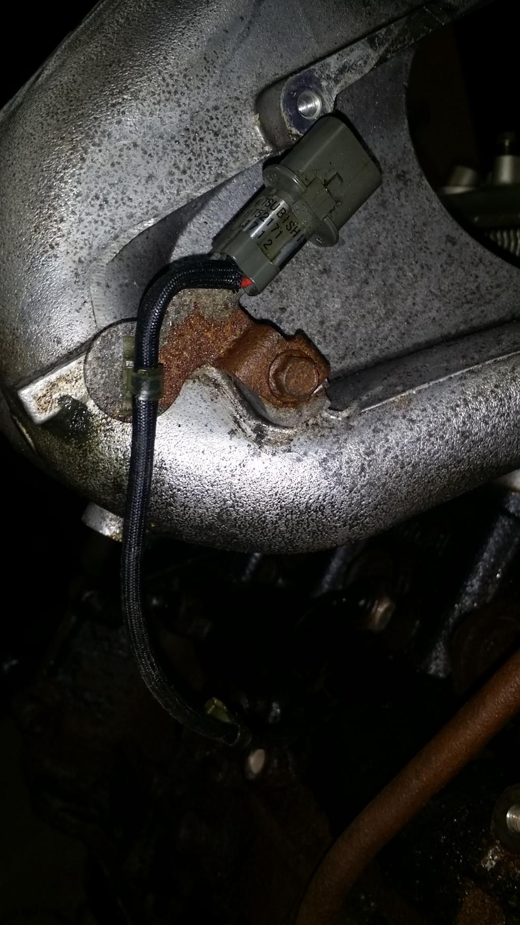
Now before I can remove the Intake Manifold I need to free it of the knock sensor. This simply in involves one 10mm bolt on a bracket. I removed the bracket and let the wire hang from the block for now. But I put the bolt back into the Manifold so I will know where it goes later.
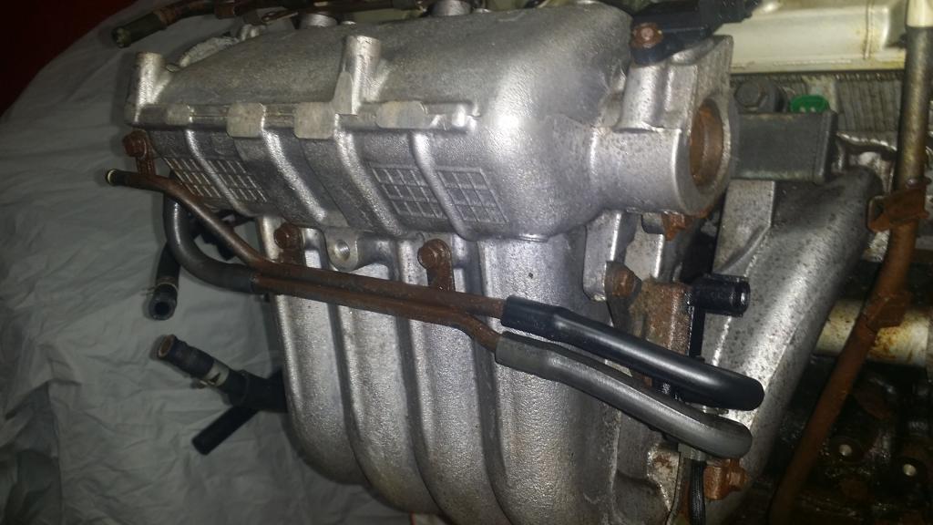
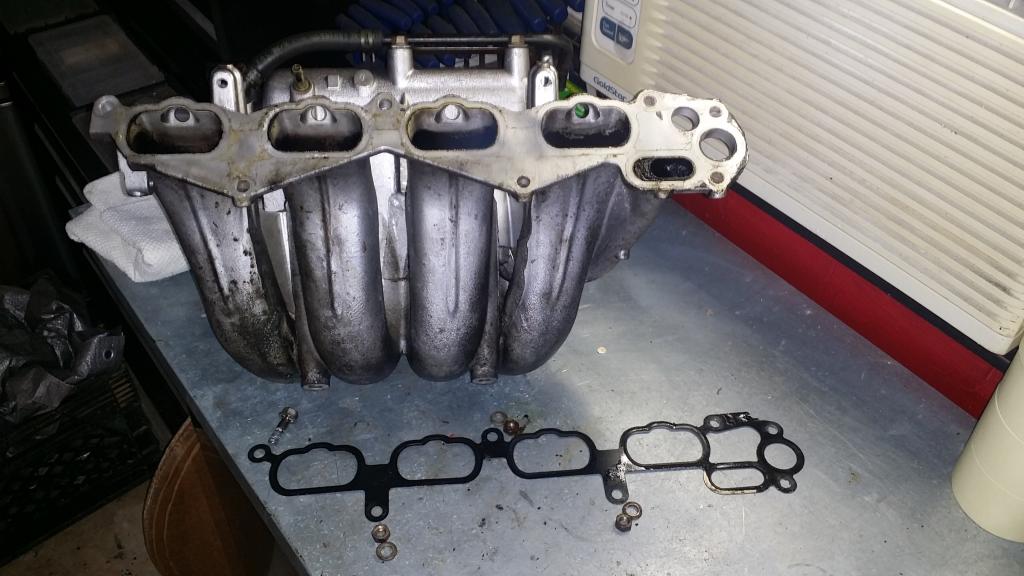
Now for the Intake Manifold. There is one 12mm bolt on the side with the dipstick, and three 12mm nuts with crush washers, one on top and two on bottom. Take those off and the Intake Manifold will be ready to fall off. Grab it and its gasket and we are finished with this chapter.
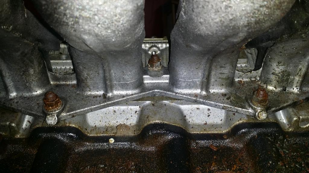
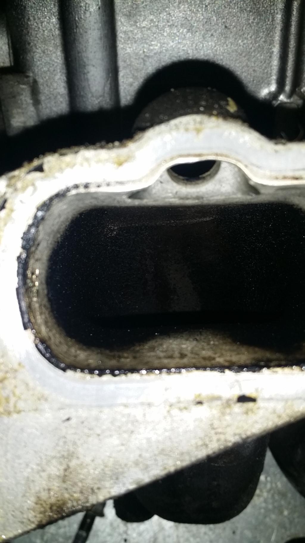
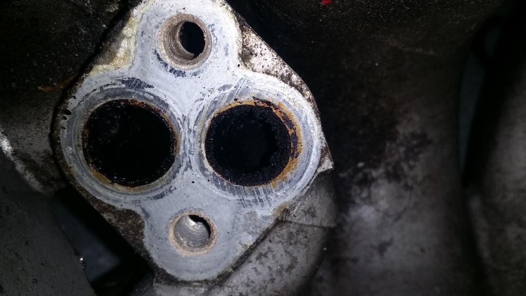
With some close inspection we can see the results of the EGR valve, and the PCV valve. All the black is exhaust gases, and oil blow by introduced by the previously named valves... I have a solution to keep this clean and keep that gunk from clogging up my manifold, and valves. Another thread for another time though I suppose.
So that�s it for the IM and Water Pump chapter. We are getting down to the basics now. I�ve been skipping on removing a lot of the sensors. I'll probably make a chapter to cover those in more detail soon.
Intake Manifold and Water Pump
Removing the manifold and pump involves quite a few parts. Hoses, Pump, Gaskets, O-rings, Pipes, Supports, Gauges, Fittings, Thermostat, Housings, Sensors, the Manifold, and Switches. But we'll probably get through this one pretty quick.
First order of business. Remember those hoses we removed from the Throttle Body? Let�s get those off first. You probably know the routine for these guys by now.
Now we go straight for the Water Pump and its gasket. To do so remove the five 12mm bolts holding it in place. I had to wrestle with it a bit to get it off of the water pipe, but it eventually let go. The gasket however split, half on the pump, and half on the block. I had to scrap the pieces off the block. Also there are 3 different bolt lengths please refer to the bench picture on where they go.
With that done we can go ahead and remove the Water Pipe. This is only held in place with a single 12mm bolt, I used a long extension to reach it. Takes some wiggling but the O-ring in the Thermostat housing will eventually come loose.
Next is the Intake Manifold Support. Four 14mm bolts hold this in place. There is also a small plastic clip that supports the wire for the Knock sensor. Pinch it form the inside with some needle nose pliers then pull it free from the wire side.
The next parts we will remove will be the Engine Coolant Temperature Gauge Unit, The Water Inlet Fitting, Thermostat, and Thermostat Housing.
Instead of breaking this down I think I will just remove them all together. To do so we will just remove the Thermostat Housing and everything will come with it. The Housing is held in place with three 12mm bolts. There was a lot of RTV holding it on, so I convinced it do come off with a rubber hammer. BTW in the first pic does anyone know what that hole with all the RTV is supposed to be? It goes on into the head and I don�t remember removing anything from there...
I�m going to skip ahead a bit here and go ahead and remove the Water Outlet Fitting. I had to loosen a couple of brackets attached to this piece so that I could get to the bolt on the bottom. The two brackets use a 10mm bolt each, and the Fitting uses two 12mm bolts. Again there is a lot of RTV on this piece, I used my trusty rubber mallet to remove it.
Now before I can remove the Intake Manifold I need to free it of the knock sensor. This simply in involves one 10mm bolt on a bracket. I removed the bracket and let the wire hang from the block for now. But I put the bolt back into the Manifold so I will know where it goes later.
Now for the Intake Manifold. There is one 12mm bolt on the side with the dipstick, and three 12mm nuts with crush washers, one on top and two on bottom. Take those off and the Intake Manifold will be ready to fall off. Grab it and its gasket and we are finished with this chapter.
With some close inspection we can see the results of the EGR valve, and the PCV valve. All the black is exhaust gases, and oil blow by introduced by the previously named valves... I have a solution to keep this clean and keep that gunk from clogging up my manifold, and valves. Another thread for another time though I suppose.
So that�s it for the IM and Water Pump chapter. We are getting down to the basics now. I�ve been skipping on removing a lot of the sensors. I'll probably make a chapter to cover those in more detail soon.
 Feb 5, 2015, 07:15 AM
#14
HA! You should have seen it before I sprayed it down with acid... lol
-------
Im hoping to get back out there tonight to write a chapter on all the sensors, and get them all removed.
Had an insane week at work so far. Lets just say that as of 11am Wednesday, I had put in my hours for the entire week...
-------
Im hoping to get back out there tonight to write a chapter on all the sensors, and get them all removed.
Had an insane week at work so far. Lets just say that as of 11am Wednesday, I had put in my hours for the entire week...
Last edited by bakuro117; Feb 5, 2015 at 07:17 AM.
Feb 8, 2015, 11:08 AM
#15
Fabulous post Bakuro, the insightful details that only a hands-on build can reveal are gold.
Crans, you mentioned you might do a tranny posting. Mine is ready to be lowered from the engine bay, if anything I'm doing could help with your "how to" lemme know.
Crans, you mentioned you might do a tranny posting. Mine is ready to be lowered from the engine bay, if anything I'm doing could help with your "how to" lemme know.

