Pajero Evolution Need xml

 Aug 30, 2011, 03:00 PM
#17
Newbie
Thread Starter
Aug 30, 2011, 03:13 PM
#18
Evolved Member

acamus, there could also be a Load threshold judgment for MIVEC as well as rpm.
And a water temperature judgment.
edit:
that 0x0064 looks a good candidate for a switching temp, ie 60*C (speculation here).
And a water temperature judgment.
edit:
that 0x0064 looks a good candidate for a switching temp, ie 60*C (speculation here).
Last edited by merlin.oz; Aug 30, 2011 at 03:33 PM.
Aug 30, 2011, 09:48 PM
#19
Evolved Member
Join Date: Mar 2008
Location: Lattitude 48.38�, Longitude 17.58�, Altitude 146m = Slovakia, for common dude
Posts: 730
Likes: 0
Received 2 Likes
on
2 Posts
So one can check it attaching voltmeter/multimeter to the solenoid and sending Custom request 0xD4 from EvoScan.
Aug 30, 2011, 09:55 PM
#20
Evolved Member
Join Date: Mar 2008
Location: Lattitude 48.38�, Longitude 17.58�, Altitude 146m = Slovakia, for common dude
Posts: 730
Likes: 0
Received 2 Likes
on
2 Posts
which tells the engine passed the readiness check and the actuator check except the RPM hysteresis.
Maybe we have a wrong output, but this one is the only that I could identify as "unknown".
Sep 11, 2011, 10:30 AM
#21
Newbie
Thread Starter
Sorry its taken me so long but as i said i'm away for days sometimes weeks in the lorry's.
Anyways entred 0xD4 and nothing no voltage to solenoids, i tried with ignition just on and with it running with both the reflash connector connected and disconnected, hope this helps.
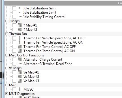
Also now that i'v had some time i notice that there is reference to 4 'thermo fan' settings when it has a belt driven viscous fan for cooling and the air con has an electric fan controlled by the main air con control unit with full air con=on, economy=intermittent or off and not affected by the engine status. Or am I missing the point?
Anyways entred 0xD4 and nothing no voltage to solenoids, i tried with ignition just on and with it running with both the reflash connector connected and disconnected, hope this helps.
Also now that i'v had some time i notice that there is reference to 4 'thermo fan' settings when it has a belt driven viscous fan for cooling and the air con has an electric fan controlled by the main air con control unit with full air con=on, economy=intermittent or off and not affected by the engine status. Or am I missing the point?
Last edited by PajEVO; Sep 11, 2011 at 03:36 PM.
Sep 11, 2011, 03:43 PM
#22
Newbie
Thread Starter
I.m not sure weather trying to flash a different value is a good idea untill the xml is correct, I mean as it is is it safe to try a flash knowing that other peramitres may not be totaly correct yet like inputting 0xD4 in evoscan having no effect, would i be flashing the rong data to the rong place etc, etc.
Sep 12, 2011, 04:01 AM
#23
Evolved Member
Well, your car may be setup with a belt drive fan, but the tables to control an electric fan are in there. Maybe a legacy item, maybe for other models or factory competition cars - dont know.
As for not flashing until the xml is proven, it is up to you to prove the xml.
Nobody else has asked for this or expressed an interest and there are no pajero Evolutions here in Oz.
As for not flashing until the xml is proven, it is up to you to prove the xml.
Nobody else has asked for this or expressed an interest and there are no pajero Evolutions here in Oz.
 Sep 12, 2011, 01:54 PM
#25
Newbie
Thread Starter
Well, your car may be setup with a belt drive fan, but the tables to control an electric fan are in there. Maybe a legacy item, maybe for other models or factory competition cars - dont know.
As for not flashing until the xml is proven, it is up to you to prove the xml.
Nobody else has asked for this or expressed an interest and there are no pajero Evolutions here in Oz.
As for not flashing until the xml is proven, it is up to you to prove the xml.
Nobody else has asked for this or expressed an interest and there are no pajero Evolutions here in Oz.
I understand what your stating, and i'm not saying that i dont trust the work acamus and yourself have put in to this, as its on the contrary; I have full trust in you both
 It's me I dont trust, through lack of knowladge about flashing etc and as such unable to make a qualified decision being that the 0xD4 request had no positive result. I merely wanted to have your opinion and advise before I acted in haste and bricked my ecu.
I'm totaly new to ecu flashing etc and had no intention of flashing untill i fully understand what i'm doing - the help you have provided thus far has educated me 10fold and i learn pretty quick. I have borrowed a copy of ida pro from a friend and have begun to follow some of the tutorials on this forum with great results, but in no way to i understand what i'm doing but its coming together quickly.
I'm more than prepared to be a 'test bunny' and fully understand and accept the risks.
I would rather be testing under the experienced guidance of yourselvs than playing lucky dip in the dark.
Anyway i hope i'v not offended you by not wording my previous post correctly and please accept my appologies if I have as is not intentional.
Ok, what you say regards the fans is that the provisions are present i understand that and can see some possible future modifications if the connections are present on thee ecu.
Now that I am aware that there is no direct connection in actuating 0xD4 in evo scan and the MIVEC settings in ecuflash; can you sugest suitable values to input for off, and on, as i'm not sure how they equate to the real-time switching, and what will the effective change cause?
I can only assume that the current values work as follows :-
off=3594 RPM is the absolute point from off > to a process where fuel, timing and intake adjustment begin to take place up to the point where at- (on=3812) RPM the solenoids are energised and the engine is under full MIVEC conditions.

or,
(normal operation) below 3594 rpm, then (transition from normal to mivec) and then at 3812 rpm and above (mivec operation) ???
Originally Posted by acamus
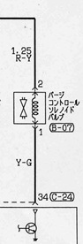
You would better test ground connectivity, the ECU switches the ground for solenoids.
Wouldn they require both live and ground regardless weather negative or positively switched, or have i just missed the point lol?
Please excuse my ignorance in being a newbie to all this and the silly questions and be assured that I understand you have other more important issues and that i will be more than willing to make some contributions at some point for your help and efforts. As I said i pick things up quite quickly and have the desire and determination to understand and at some point be able to tune my evo correctly and without risk of damage.
Sorry this post has been so long,
 It has taken me nearly 3 hours to write.
Sep 13, 2011, 02:12 AM
It has taken me nearly 3 hours to write.
Sep 13, 2011, 02:12 AM
#26
Evolved Member
Connect a multimeter (set to 20 volts DC scale, or auto DC scale, whatever suits what meter you have) across the solenoid as shown in Acamus' diagram.
When the solenoid is de-energised the voltage should be something less than 1 VDC.
When the solenoid is energised, the voltage should be battery voltage (more-or-less).
Warm the engine, drive with the meter in the cabin with you and check at what rpm the solenoid is energised/ed-energised.
If we have the correct items defined, they should match the predicted rpm.
If not, the data you collect should help us find the correct values etc.
It is possible that the MIVEC solenoid does not get activated until a specified temp is exceeded, lots of ECU functions have temp control settings.
Sep 18, 2011, 07:52 AM
#27
Newbie
Thread Starter
Sorry for not posting back when i said i would (work lol) any way; Since the engine has the solenoids for valve timing and also has variable intakes; controlled by vacum via an open/shut electro valve, i put two meters on at the same time, one on each and had the following results :-
The engine has a variable intake system ehere the actuator is operated by vacum from the manifold via an electric valve, however this has a continous 12v feed when ignition is on/running and droppes to 0 volts when activated. The voltage changes from 12v to 0v operating the variable intake at appx 3800 Rpm and then changes back to 12v when the RPM decends to appx 3600 Rpm thus turning the variable intake back off, which is around the same two values in previously mentioned.
Valve timing solenoids energised around approx 5000 Rpm initialy at battery voltage (12-13v) but then dropped to half that (6-7v) 1-2 seconds or so later.
I think this is just to avoid exessive wear/heat to the coils when energised for longer periods ie when cruzing under load at speeds etc but just my opinion.
You probably know how it works but i thought i'd say just in case the system is different to other MIVECs.
I also got verry brave (well for me anyway) I decided to flash a different value to the 'Target Idle RPM - Drive' map as it is a little lumpy at idle - probably due to the aftermarket induction system and checked by reading the rom back with positive results. So i'v given myself a pat on the back But you guys really rock for making this possible for me, without all the possibillities yet to come.
Sep 18, 2011, 02:49 PM
#28
Evolved Member
^ That is good info, did not know it had a variable Intake Manifold system, it seems that Accamus' output variables are spot on for that function.
And from your measured results on the MIVEC solenoid, it seem like it may be using a pulse width modulated control, which would imply a 3D control map.
This is currently not found or, possible incorrectly defined.
Were the measurement made with a digital multimeter?
If you can find an old analog meter to repeat the same measurement, that should show a more linear PWM measurement. Better yet, find a techo with an oscilloscope!
You could try wiring a low wattage dash lamp across the solenoid and into the cabin.
A PWM signal should get it changing brightness.
Sep 18, 2011, 08:53 PM
#29
Newbie
Thread Starter
ok, already done that when i tested, used a 5w bulb in place of the digital meter as i dont currently have axcess to an analouge type (but have plans to buy a HPS140 handheld pocket oscilloscope for it's many valuable uses) and yes initialises at full brightness then falls back to appx half its brightness untill the rpm drops then goes from half bright to off. I am not sure weather the solenoid is variable with voltage as yet but will investigate, but from what i can gather from the collection of pdf's i have the valve timing is either on or off which to me just says that 12v gives the initial push to open the valve against the force of the oil pressure an then fall to a lesser value to preserve the life/durabillity of the coil windings in the solenoid, this is just an opinion at the moment, i'm looking at cross referencing some part numbers to maybe find the spec of the vvt solenoids and at a push will remove one to confirm if needed. I'll post this confirmation as soon as possible.
Ok changing the subject slightly, if I were to trace the loom wires to and from the various components/destinations etc and map the corresponding pinout of the ecu to form a diagram, would this in any way help to id the correct definitions. This will itself will be quite a task as the engine loom appears to be grafted on to the existing MK3 pajero loom just as it exits the bulk head, (maybe from an FTO??) will be time consuming but well within my caperbillities. and if helpfull is there any that would be first choice on the list??
Ok changing the subject slightly, if I were to trace the loom wires to and from the various components/destinations etc and map the corresponding pinout of the ecu to form a diagram, would this in any way help to id the correct definitions. This will itself will be quite a task as the engine loom appears to be grafted on to the existing MK3 pajero loom just as it exits the bulk head, (maybe from an FTO??) will be time consuming but well within my caperbillities. and if helpfull is there any that would be first choice on the list??

