DIY: Viper 5701 Install on CT9A
 Jun 8, 2011, 10:21 AM
#121
Newbie

Join Date: Jul 2007
Location: San Jose
Posts: 20
Likes: 0
Received 0 Likes
on
0 Posts
Here, you have three options;
The best is to get another key, this allows the transponder to still work correctly.
The second is to get non-transponder keys cut to use for the ignition and put your working key into a bypass module. Then trigger the module with the ignition wire instead of the remote start status output. Any time the ignition is on it will send the rfid from the key in the box.
Finally you can disable the transponder via flashing the ecu.
 Jun 8, 2011, 04:36 PM
#122
Evolving Member
iTrader: (6)

Join Date: Apr 2010
Location: Tulsa, OK
Posts: 107
Likes: 0
Received 0 Likes
on
0 Posts
You can disable it anytime, just read the file on your ecu, change the transponder bit to all 0's (correct me if I'm wrong) then re-write the changed file to the ecu.
And yes your relay diagrams look good.
And yes your relay diagrams look good.
Last edited by Marcac; Jun 8, 2011 at 04:38 PM.
Jun 14, 2011, 04:14 AM
#123
Newbie
Join Date: Jul 2007
Location: San Jose
Posts: 20
Likes: 0
Received 0 Likes
on
0 Posts
Thanks!!! I think I can figure it out now 
FYI. The whole immobilizer comment sent me into a frenzy of looking for how-to's. Which lead me to looking for self tuning, etc. Now it looks like when I get back to my Evo, it'll be remote start with no PKU-MIT and datalog pulls
FYI. The whole immobilizer comment sent me into a frenzy of looking for how-to's. Which lead me to looking for self tuning, etc. Now it looks like when I get back to my Evo, it'll be remote start with no PKU-MIT and datalog pulls
Aug 19, 2011, 08:48 PM
#129
Newbie

Join Date: Jun 2011
Location: Italy
Posts: 3
Likes: 0
Received 0 Likes
on
0 Posts
Hi all
I'm Alex, i write from Italy and I need your help

I'm installing a 5902 Viper Allarm System (apparently the same wiring of 5701 Viper Allarm) on my 2007 EDM EVO IX and i have some question for you:
Harness #1
PARKING LIGHT OUTPUT---------------------WHITE----------------------------green/white----------------------door kick panel
Door Lock Harness
Function--------------------------------------- alarm wire---------------------vehicle wire--------------------location
UNLOCK OUTPUT---------------------------------Blue-----------------------------light green --------------------door kick panel
LOCK OUTPUT-------------------------------------Green--------------------------violet ---------------------------door kick panel
Where can I find this wire on my EVO IX? Which plug do I find them? I looked on the Mitsubishi wiring diagrams but can not find them.
Also I have found the Mitsubishi wiring diagrams only for RHD driving and some wire color is different from my EDM LHD
I hope you can help me.
thanks
Alex
I'm Alex, i write from Italy and I need your help
I'm installing a 5902 Viper Allarm System (apparently the same wiring of 5701 Viper Allarm) on my 2007 EDM EVO IX and i have some question for you:
Harness #1
PARKING LIGHT OUTPUT---------------------WHITE----------------------------green/white----------------------door kick panel
Door Lock Harness
Function--------------------------------------- alarm wire---------------------vehicle wire--------------------location
UNLOCK OUTPUT---------------------------------Blue-----------------------------light green --------------------door kick panel
LOCK OUTPUT-------------------------------------Green--------------------------violet ---------------------------door kick panel
Where can I find this wire on my EVO IX? Which plug do I find them? I looked on the Mitsubishi wiring diagrams but can not find them.
Also I have found the Mitsubishi wiring diagrams only for RHD driving and some wire color is different from my EDM LHD
I hope you can help me.
thanks
Alex
Aug 20, 2011, 06:03 AM
#130
Newbie

Join Date: Feb 2009
Location: Vermont
Posts: 32
Likes: 0
Received 0 Likes
on
0 Posts
just installed mine the other day. I had the same questions, and didn't really find the answers on the forum. i used my voltage meter and found the answers.
for the lock and unlock (light green and violet, (Yes, light green, not the green that is next to the violet)) use the wires in the harness that go into the actual door.
parking lights wire (green/white) is in the white plug at the bottom of the fuse box. (if you have your dash semi taken apart, this plug might not be connected (plugged in), so keep that in mind.) ** on another note, This wire worked fine to flash my brake lights, but does not flash my parking lights in the headlights... not sure why, but...
Brake shutdown wire is simply a brake light wire, and is green. It can be found in the driver side kick panel bottom white plug. (there are a lot of wires in this plug)
If you are doing all of this, you must be doing the remote start. The only thing i haven't done is to bypass the clutch switch using the spdt relay. Apprently, there are two lines connected to the clutch switch, one is always grounded, and the other is sometimes grounded, you should cut the sometimes grounded wire, and connect that to the relay. A diagram can be found on the last post of page 8 on this thread. not sure of the wire color. Also, I don't know what GWR (ground when running) means, or how i'm supposed to do that, as the keybypasskit i got requires a power, a ground, and a gwr as well. if you figure it out, i'd appreciate any input.
Harrison
Aug 20, 2011, 02:48 PM
#131
Newbie
Join Date: Jun 2011
Location: Italy
Posts: 3
Likes: 0
Received 0 Likes
on
0 Posts
just installed mine the other day. I had the same questions, and didn't really find the answers on the forum. i used my voltage meter and found the answers.
for the lock and unlock (light green and violet, (Yes, light green, not the green that is next to the violet)) use the wires in the harness that go into the actual door.
parking lights wire (green/white) is in the white plug at the bottom of the fuse box. (if you have your dash semi taken apart, this plug might not be connected (plugged in), so keep that in mind.) ** on another note, This wire worked fine to flash my brake lights, but does not flash my parking lights in the headlights... not sure why, but...
Brake shutdown wire is simply a brake light wire, and is green. It can be found in the driver side kick panel bottom white plug. (there are a lot of wires in this plug)
If you are doing all of this, you must be doing the remote start. The only thing i haven't done is to bypass the clutch switch using the spdt relay. Apprently, there are two lines connected to the clutch switch, one is always grounded, and the other is sometimes grounded, you should cut the sometimes grounded wire, and connect that to the relay. A diagram can be found on the last post of page 8 on this thread. not sure of the wire color. Also, I don't know what GWR (ground when running) means, or how i'm supposed to do that, as the keybypasskit i got requires a power, a ground, and a gwr as well. if you figure it out, i'd appreciate any input.
Harrison
for the lock and unlock (light green and violet, (Yes, light green, not the green that is next to the violet)) use the wires in the harness that go into the actual door.
parking lights wire (green/white) is in the white plug at the bottom of the fuse box. (if you have your dash semi taken apart, this plug might not be connected (plugged in), so keep that in mind.) ** on another note, This wire worked fine to flash my brake lights, but does not flash my parking lights in the headlights... not sure why, but...
Brake shutdown wire is simply a brake light wire, and is green. It can be found in the driver side kick panel bottom white plug. (there are a lot of wires in this plug)
If you are doing all of this, you must be doing the remote start. The only thing i haven't done is to bypass the clutch switch using the spdt relay. Apprently, there are two lines connected to the clutch switch, one is always grounded, and the other is sometimes grounded, you should cut the sometimes grounded wire, and connect that to the relay. A diagram can be found on the last post of page 8 on this thread. not sure of the wire color. Also, I don't know what GWR (ground when running) means, or how i'm supposed to do that, as the keybypasskit i got requires a power, a ground, and a gwr as well. if you figure it out, i'd appreciate any input.
Harrison
I taken a few pictures of the my OEM EDM IX wiring:
J/B Junction Block under the steering
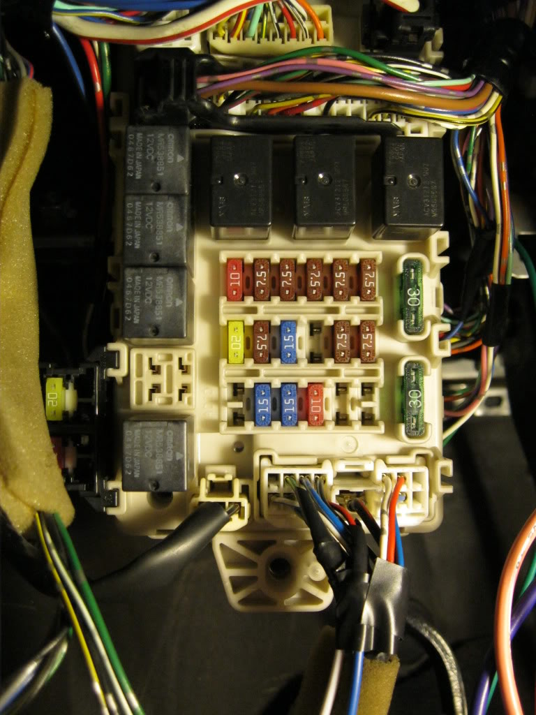
I connected this wires:
Harness #1
Door Trigger Input ---------------------------Green-----------------------------blue in grey plug. It's same blue wire instrument cluster (blue plug)
trunk trigger -----------------------------------BLUE-----------------------------red/black in first white plug in the lower right (it's same green/orange in trunk)
PARKING LIGHT OUTPUT---------------------WHITE----------------------------green/yellow in first white plug in the lower right
with these connections when arming and disarming the alarm the front and rear parking lights (and licence plate light
 ) are flashing
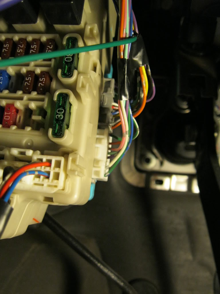
Now I have problems with lock and unlock doors.
This is a J/C Junction Connector in a driver side door kick pannel. The door plug is the second plug from the top
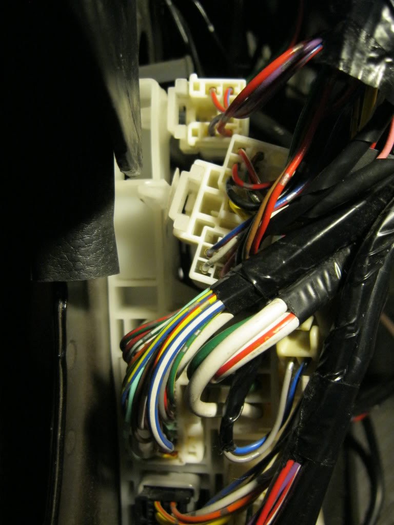
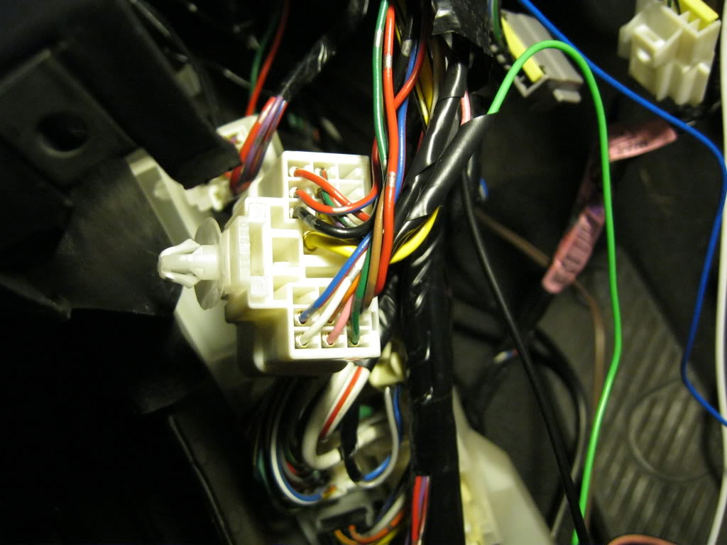
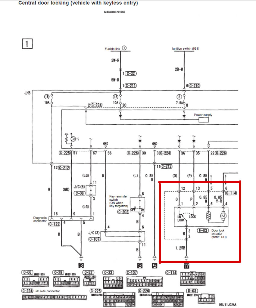
The orange and pink wire control the lock and unlock doors (pink lock and orange unlock). I connected green alarm wire whit pink car wire and blue alarm wire whit orange car wire but don't work
Where did I go wrong?

This is a wire diagram for central door locking RHD (apparently same color of LHD but inverted)
Last edited by Never Mind; Aug 20, 2011 at 03:36 PM.
 Aug 22, 2011, 08:31 PM
#133
Newbie
Join Date: Jun 2011
Location: Italy
Posts: 3
Likes: 0
Received 0 Likes
on
0 Posts
To make operating the lock unlock alarm i had to kill the orange & pink car wire but is a temporary solution because in this way the driver's side swich only closes its doors (not all). The alarm and the keyless key close all door.
I had to do this because when the cables are in use is always mass (the other cable has no tension). The alarm instead sends the input ground (0.8s or optional 3.5s) on the wire to be controlled and in this way the OEM ECU reads both cables to ground and does not work.
To make all perfectly working I have to build a circuit with 2 relays that control the +12v motor actuator wires with two negative wires alarm.
Last edited by Never Mind; Aug 22, 2011 at 08:47 PM.
Sep 28, 2011, 04:47 AM
#135
Newbie
Join Date: Feb 2009
Location: Vermont
Posts: 32
Likes: 0
Received 0 Likes
on
0 Posts
Look at the pictures above. "door kick panel" simply means in that general area. you can also see my post #130 for more details on what wires are where. the door lock/unlock are behind all the connectors and actually head into the door.
on another note regarding my previous post, after researching i have a feeling that my front parking light bulbs are just blown, and thats why they don't flash. I'll be testing this today. But the wire listed is the correct one to tap into.
Edit again, I'm messing around with getting my remote start working with the bypass key thing. If you are doing the same and have any questions, i'll try and help you out... as long as i get mine working! lol.
Last edited by Jaded-7; Sep 28, 2011 at 04:50 AM.