fuel pump wire with high/low voltage circuit
 Dec 24, 2011, 04:46 PM
#1
fuel pump rewire with high/low voltage circuit
Feb 5, 2015 Update:
I realized a while ago that there is a far easier solution. See post #121.
This is what I used, but is way more complex than the solution in post #121.
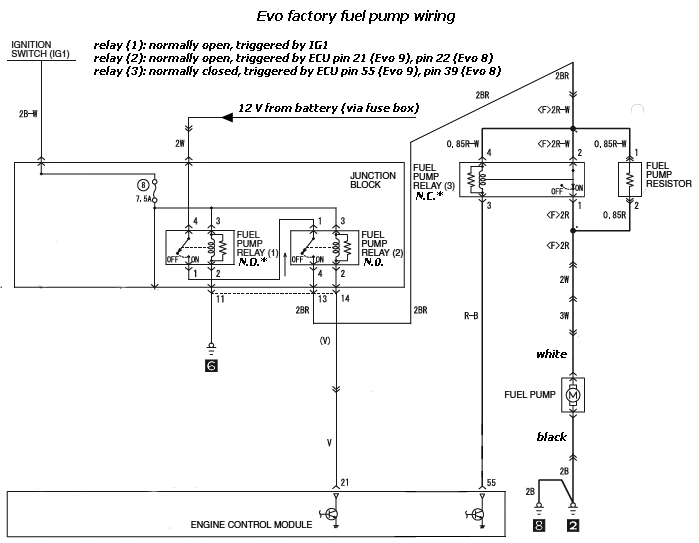
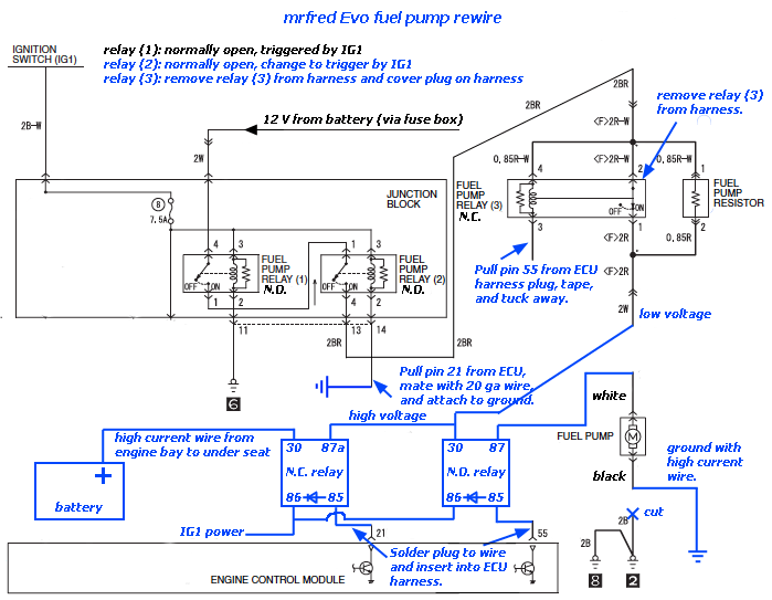
FWIW, here's my rendition of a high power fuel pump rewire that preserves the low/high voltage (high voltage = battery voltage) circuit and triggers off the factory ECU logic. The basic plan is to rig the factory low/high voltage circuit to run only in low voltage mode, and then run a new high voltage wire from the battery back to the fuel pump where two relays are used, one to switch between low/high voltage, and the other to disable the fuel pump power circuit when the key is "on", but the engine is "off". Diagrams of the factory wiring schematic and the modified schematic are shown below.
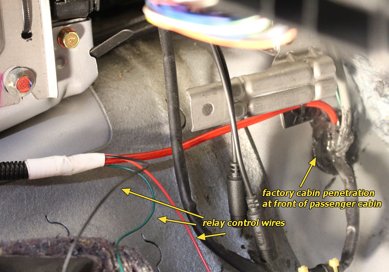
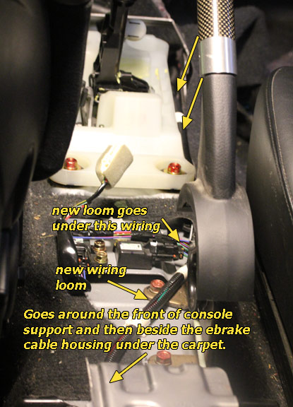
I ran the power wire from the battery down the back of the engine bay and into the passenger compartment where most people run the wideband wiring. From the point where the high power wire runs into the passenger cabin, I ran it under the console, under the carpet on the tunnel, and then it pops out from under the carpet on the far left side of the rear seat. The three 18-22 gauge wires run together with the power wire from under the dash to the fuel pump. The two relays are set up under the seat.
The aftermarket electromechanical relays are susceptible to degradation over time. I'm contemplating replacing them with solid state relays (SSR).
Required parts:
- Good standard rewire kit. I started with the STM kit that includes a universal N.C./N.O. relay.
- Three 8 foot lengths of 18-22 gauge wire, each a different color.
- An additional 6 foot length of corrugated wiring sheath big enough for the high power wire and the three additional wires.
- An additional 30+ amp automotive relay. Can be universal N.C./N.O. or just N.O.
- The relay control circuit on the relay (pins 85/86) should be diode protected to ensure the power transistors in the ECU do not get damaged from flyback voltage when the control circuit is opened. This can be accomplished with either a diode attached to the relay plug, or by using relays that have the diode built-in.
- Any items needed to secure the wiring and relays.
January 2, 2012 Update:
Rewire is complete, and the high/low voltage feature is working. I had to do things slightly differently than I had originally planned. The diagram below is updated with the changes. I'll try to post some pictures of the rewire job later tonight.
The rewire substantially increases fuel flow in high (battery) voltage mode even with a Walbro 255. With the factory low/high voltage switch point of 0 psi (crossover from vacuum to boost), the rewired Walbro 255 causes a ~10 psi jump in fuel pressure, so either I need to raise the crossover point to a higher boost level, or I need to switch to an aftermarket FPR. I plan to try to tinker with the crossover point first. It appears that the crossover point is based on load, but it seems that is should be based more on air flow, so once I find the code, I may rewrite it to switch with MAF Hz rather than load.
January 6, 2012 Update:
Here is the table in the 88590015 ROM for controlling the low/high voltage crossover point:
By setting the high voltage load to match the open loop load, I was able to pretty much completely eliminate the fuel pressure overrun I was getting when high voltage would kick in during off-boost driving. I'm pretty stoked at how well this is working out.
So, I must admit that I'm a bit worried about using a universal automotive relay to control the low/high voltage transition. The low/high voltage transition takes quite a bit during normal driving, and I worry that these universal automotive relays are not up to the job. I've decided that I'm going to use a solid state relay (SSR) for the high/low voltage switch. SSRs switch extremely quickly, and pretty much never wear out. I'll report back after I've tried it out.
Factory fuel pump wiring diagram
Rewire to preserve high/low voltage system
Pump wiring at front of passenger cabin. Relay control wiring has not been hooked up to ECU and IG1 power yet.
Pump wiring running along drive shaft tunnel.
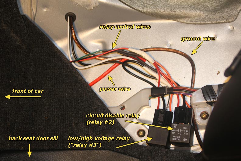
Completed pump wiring near the fuel pump. Electromechanical relays being utilized in this setup.
I realized a while ago that there is a far easier solution. See post #121.
This is what I used, but is way more complex than the solution in post #121.
FWIW, here's my rendition of a high power fuel pump rewire that preserves the low/high voltage (high voltage = battery voltage) circuit and triggers off the factory ECU logic. The basic plan is to rig the factory low/high voltage circuit to run only in low voltage mode, and then run a new high voltage wire from the battery back to the fuel pump where two relays are used, one to switch between low/high voltage, and the other to disable the fuel pump power circuit when the key is "on", but the engine is "off". Diagrams of the factory wiring schematic and the modified schematic are shown below.
I ran the power wire from the battery down the back of the engine bay and into the passenger compartment where most people run the wideband wiring. From the point where the high power wire runs into the passenger cabin, I ran it under the console, under the carpet on the tunnel, and then it pops out from under the carpet on the far left side of the rear seat. The three 18-22 gauge wires run together with the power wire from under the dash to the fuel pump. The two relays are set up under the seat.
The aftermarket electromechanical relays are susceptible to degradation over time. I'm contemplating replacing them with solid state relays (SSR).
Required parts:
- Good standard rewire kit. I started with the STM kit that includes a universal N.C./N.O. relay.
- Three 8 foot lengths of 18-22 gauge wire, each a different color.
- An additional 6 foot length of corrugated wiring sheath big enough for the high power wire and the three additional wires.
- An additional 30+ amp automotive relay. Can be universal N.C./N.O. or just N.O.
- The relay control circuit on the relay (pins 85/86) should be diode protected to ensure the power transistors in the ECU do not get damaged from flyback voltage when the control circuit is opened. This can be accomplished with either a diode attached to the relay plug, or by using relays that have the diode built-in.
- Any items needed to secure the wiring and relays.
January 2, 2012 Update:
Rewire is complete, and the high/low voltage feature is working. I had to do things slightly differently than I had originally planned. The diagram below is updated with the changes. I'll try to post some pictures of the rewire job later tonight.
The rewire substantially increases fuel flow in high (battery) voltage mode even with a Walbro 255. With the factory low/high voltage switch point of 0 psi (crossover from vacuum to boost), the rewired Walbro 255 causes a ~10 psi jump in fuel pressure, so either I need to raise the crossover point to a higher boost level, or I need to switch to an aftermarket FPR. I plan to try to tinker with the crossover point first. It appears that the crossover point is based on load, but it seems that is should be based more on air flow, so once I find the code, I may rewrite it to switch with MAF Hz rather than load.
January 6, 2012 Update:
Here is the table in the 88590015 ROM for controlling the low/high voltage crossover point:
Code:
<table name="Min Load for Fuel Pump High Voltage" category="Fuel" address="3fce" type="2D" level="1" scaling="Load8">
  <table name="Engine Speed" address="6b7a" type="Y Axis" elements="10" scaling="RPM"/>
</table>
So, I must admit that I'm a bit worried about using a universal automotive relay to control the low/high voltage transition. The low/high voltage transition takes quite a bit during normal driving, and I worry that these universal automotive relays are not up to the job. I've decided that I'm going to use a solid state relay (SSR) for the high/low voltage switch. SSRs switch extremely quickly, and pretty much never wear out. I'll report back after I've tried it out.
Factory fuel pump wiring diagram
Rewire to preserve high/low voltage system
Pump wiring at front of passenger cabin. Relay control wiring has not been hooked up to ECU and IG1 power yet.
Pump wiring running along drive shaft tunnel.
Completed pump wiring near the fuel pump. Electromechanical relays being utilized in this setup.
Last edited by mrfred; Feb 5, 2015 at 01:57 PM.

The following users liked this post:
Tommyfacekicker (Mar 19, 2018)
Dec 25, 2011, 10:42 AM
#2

http://www.mouser.com/ProductDetail/...zB6VnogQ%3d%3d
will this one work > it appears to be NC
http://www.clare.com/home/pdfs.nsf/0/596E5AF3823828C1852572660044BCF6/$file/CPC1219.pdf
May not have enough power handling capacity though
BUT here is one that may handle 20A
http://www.vsholding.com/datasheets/...th_true_NC.pdf
will this one work > it appears to be NC
http://www.clare.com/home/pdfs.nsf/0/596E5AF3823828C1852572660044BCF6/$file/CPC1219.pdf
May not have enough power handling capacity though
BUT here is one that may handle 20A
http://www.vsholding.com/datasheets/...th_true_NC.pdf
Last edited by WRC-LVR; Dec 25, 2011 at 10:49 AM.
Dec 26, 2011, 08:10 AM
#3
http://www.mouser.com/ProductDetail/...zB6VnogQ%3d%3d
will this one work > it appears to be NC
http://www.clare.com/home/pdfs.nsf/0/596E5AF3823828C1852572660044BCF6/$file/CPC1219.pdf
May not have enough power handling capacity though
BUT here is one that may handle 20A
http://www.vsholding.com/datasheets/...th_true_NC.pdf
will this one work > it appears to be NC
http://www.clare.com/home/pdfs.nsf/0/596E5AF3823828C1852572660044BCF6/$file/CPC1219.pdf
May not have enough power handling capacity though
BUT here is one that may handle 20A
http://www.vsholding.com/datasheets/...th_true_NC.pdf
Last edited by mrfred; Dec 26, 2011 at 08:15 AM.

Trending Topics


 Jan 7, 2012, 07:54 PM
#13
Nice work
Packaging is a little rough, but International Rectifier makes some nice high side power switches. I've been looking at them for some other projects. Current and thermal protection, low on state resistance, reverse battery protection, built in charge pump to drive the high power MOSFET. Just like an SSR only smaller and cheaper.
https://ec.irf.com/v6/en/US/adirect/...uctID=AUIR3316
Packaging would definitely be the issue in this setup, but at $2 for something that can handle 20Amp with less then 2 watts lost...
Jan 7, 2012, 08:57 PM
#14
Nice work
Packaging is a little rough, but International Rectifier makes some nice high side power switches. I've been looking at them for some other projects. Current and thermal protection, low on state resistance, reverse battery protection, built in charge pump to drive the high power MOSFET. Just like an SSR only smaller and cheaper.
https://ec.irf.com/v6/en/US/adirect/...uctID=AUIR3316
Packaging would definitely be the issue in this setup, but at $2 for something that can handle 20Amp with less then 2 watts lost...
Packaging is a little rough, but International Rectifier makes some nice high side power switches. I've been looking at them for some other projects. Current and thermal protection, low on state resistance, reverse battery protection, built in charge pump to drive the high power MOSFET. Just like an SSR only smaller and cheaper.
https://ec.irf.com/v6/en/US/adirect/...uctID=AUIR3316
Packaging would definitely be the issue in this setup, but at $2 for something that can handle 20Amp with less then 2 watts lost...
I successfully used a Crydom D1D40 today for the low/high voltage switch. Seemed like there was a slight increase in circuit resistance, but very very minimal. Only lost 1 psi fuel pressure over the new electromechanical relay.
Jan 8, 2012, 09:01 AM
#15
Nice work
Packaging is a little rough, but International Rectifier makes some nice high side power switches. I've been looking at them for some other projects. Current and thermal protection, low on state resistance, reverse battery protection, built in charge pump to drive the high power MOSFET. Just like an SSR only smaller and cheaper.
https://ec.irf.com/v6/en/US/adirect/...uctID=AUIR3316
Packaging would definitely be the issue in this setup, but at $2 for something that can handle 20Amp with less then 2 watts lost...
Packaging is a little rough, but International Rectifier makes some nice high side power switches. I've been looking at them for some other projects. Current and thermal protection, low on state resistance, reverse battery protection, built in charge pump to drive the high power MOSFET. Just like an SSR only smaller and cheaper.
https://ec.irf.com/v6/en/US/adirect/...uctID=AUIR3316
Packaging would definitely be the issue in this setup, but at $2 for something that can handle 20Amp with less then 2 watts lost...
Last edited by mrfred; Jan 8, 2012 at 09:25 AM.