How To: Another DIY Catch Can mod - Dual, with baffles and extended inlet tube
 Apr 10, 2010, 07:17 PM
#1
How To: Another DIY Catch Can mod - Dual, with baffles and extended inlet tube
Edit: added the overall connection diagram at the end.
Edit: Updated information to reflect move of the PCV valve.
So I had been looking around to do a catch can mod since I switched out to a mini battery. After looking at all the aftermarket cans and reading up about them I found almost all of them had the same deficiency (in addition to being overpriced) almost none of them had any sort of baffling or even forced the air to go to the bottom of the tank before it exited. Sure they would work a little, but I know they would still let a decent amount of blow by thru.
At this point I started looking heavily into the DC3 catch can, but I did not have any great location to mount it, and it was just a little more than I wanted to spend.
So I decided to look on good old e-bay and see what they had to offer. After sifting through pages of them I came across these catch cans that appeared to have screws in them to allow me to open them up and mess with their innards. They also looked similar to Greddy/Megan catch cans and were made from aluminum so they would be decently light. So i ordered up a set of them in GUNMETAL and I received them in short order.
What a lovely shade of gunmetal eh? Well its eBay what can you expect, for just under $50 shipped for the 2 of them I couldn't complain much. I was going to attempt to strip them and just either polish them or give them a brushed look, but after seeing that the anodizing would require a stripper that was VERY toxic I deiced to just go at them with some spray paint. A note on disassembling these guys, they come with 3/8" and 3/4" nipples, and the tops and bottoms can be unscrewed. I would NOT recommend touching the bottom set of hex bolts, I had a horrible time getting one of the screws back in. The top ones came out and went back in very easily.
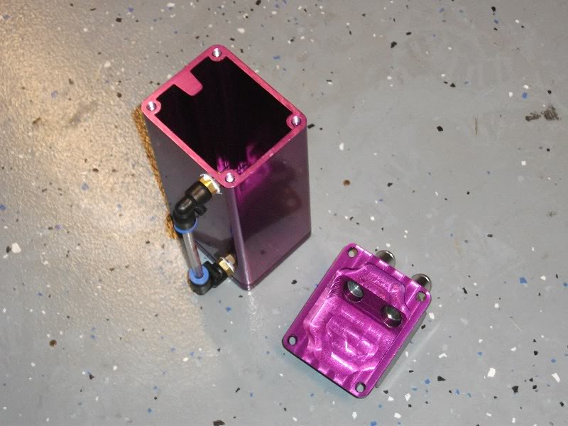
After opening it up I saw that of course there was nothing to them inside, just a hollow box with a clear tube on the side.
I ran out and purchased some aluminum to make a stand, some 'flexible' copper tubing (3/8" ID I believe), some scouring pads and 8 feet of 3/8" fuel hose (7' would have sufficed).
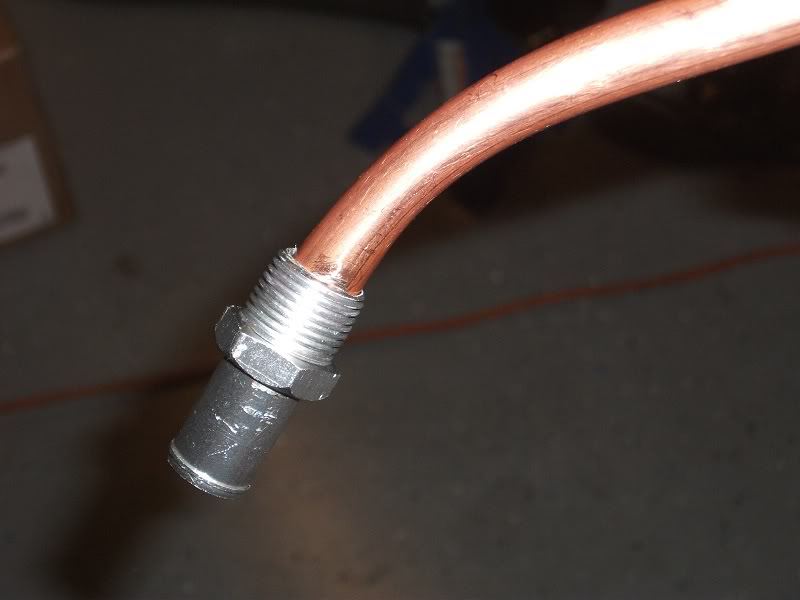
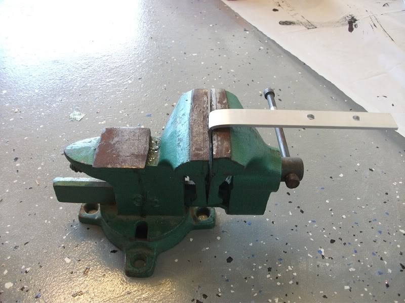
The Inner Diameter of these fittings were just slightly larger than what I needed so I put them in a vice, and increased the size of the hole to accept my copper tubing using my drill press. You could use a smaller copper tube but I had had a different idea which did not pan out so I was stuck with the size of tubing I bought.
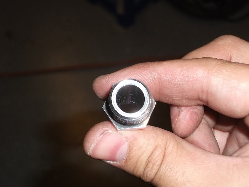
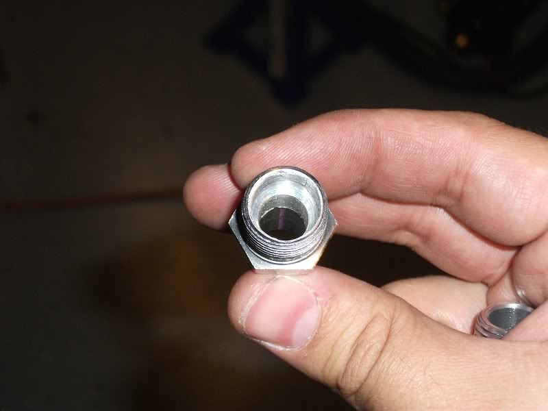
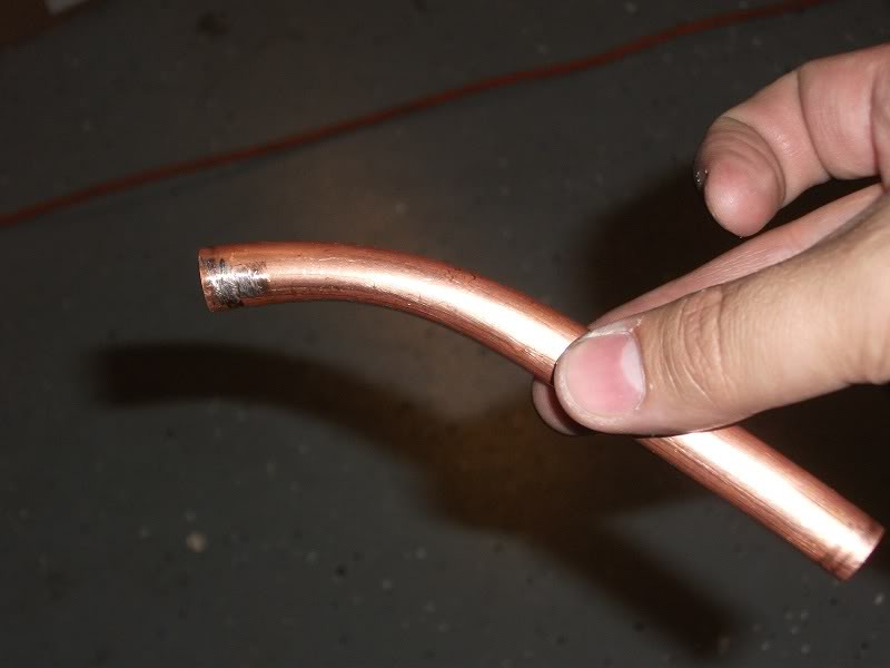
My original design called for me to bend the tube to about a 45 degree angle, this slightly compressed the tube and was frankly a bit hard to do so after the first one I deiced to pick up a copper 45 degree coupler that I managed to find at Lowe's. You'll notice the fit was fairly tight even without any sort of bonding agent.
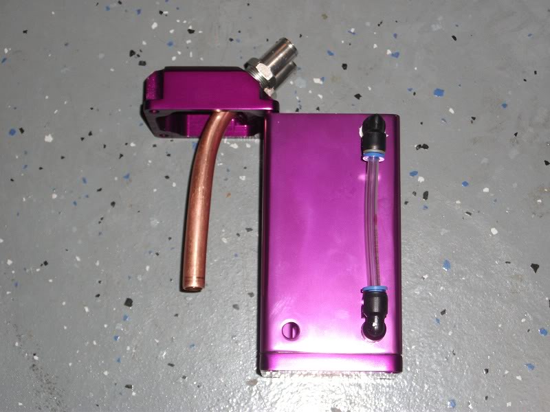
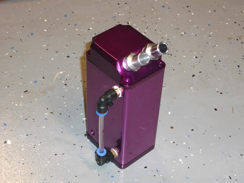
Once installed in the catch can it went almost all the way down, leaving a good one inch gap a the bottom. I connected the tubes to the aluminum in a somewhat questionable way, we'll see how it does over the long run. I decided to line the inside of the drilled out fitting with a thin layer of Red RTV Silicone I had for another project and also put a bead of it around the tube to seal it. It should hold since there should not really be any noticeable force hitting the tubes, but if it does fail I will look into alternatives. I could not screw in the fittings with the copper tubes attached so I did not want to attempt to solder the tubes in place.
At this point I made the second tube, and finished painting the cans with a high heat engine enamel. I now had the fun challenge of figuring out which direction I wanted the face the cans, originally I was going to face them both towards the motor but put the bottom on 180 degrees off of each other so I could press the 2 together. This caused a problem though since the mounting holes were going to be on opposite sides. I also thought about putting one can facing forward and one reverse, it had an interesting effect but in the end I scrapped that idea.
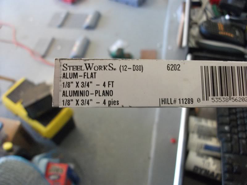
I picked up this piece of aluminum ($5) to make the mounts for the cans, they come with a small bracket but it was not going to be useful in my situation.
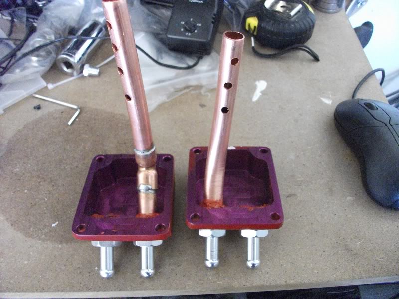
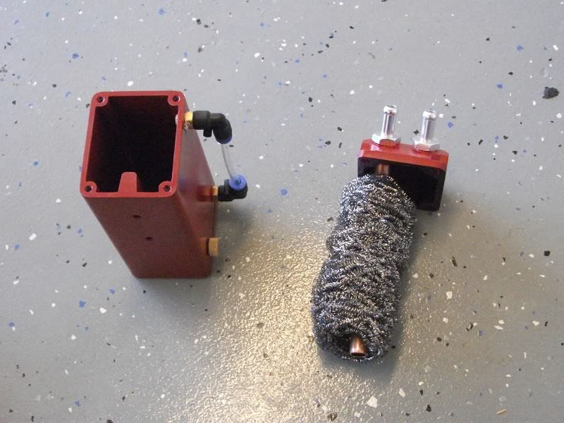
Here are the two different setups side by side, I prefer the one on the left, it was by far easier to do than trying to bend the tube and not crush it. I also had a brain fart when I was doing the cross drilling of the holes, I should have used my dowel centering jig but I did not and just tried to eyeball it on my drill press, it was somewhat of a pain, but they will serve their purpose if the can starts collecting a lot of oil.
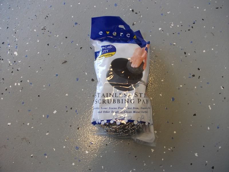
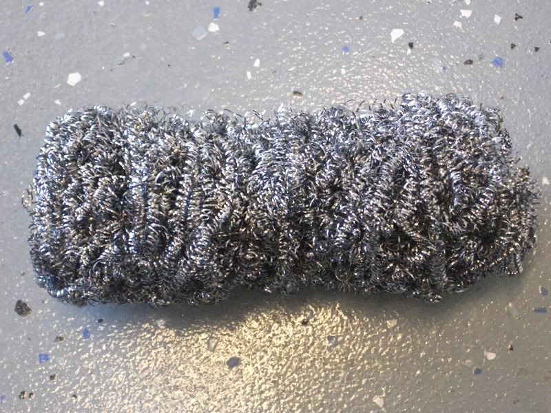
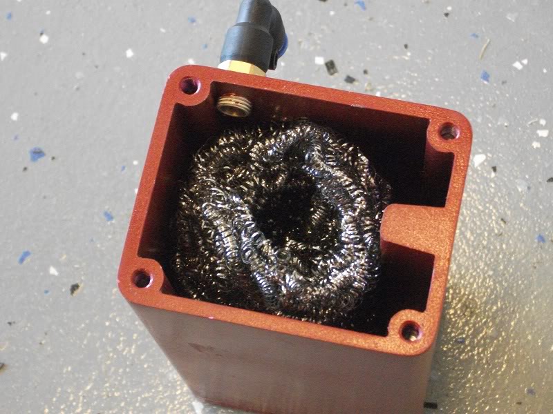
These are the stainless steel pads I bought which come 2 in a bag, they are much coarser than steel wool and they are less prone to oxidation and breaking down, I don't want bits of metal to replace the drops of oil going into my intake track. I thought of some other baffling materials, but this was a reasonably priced offering that I think would do the trick. They come in this nice little ball shape, but you can easily work the material into this cylindrical torus shape, with a convent shaft down the middle to insert the copper tube. 1 pad fit quite nicely in the catch can so I used one in each.
I then proceeded to create the mounting bracket. Using my Dremel I cut the aluminum to 7.5" to allow for a 1.5" bottom anchor point. In this shot I bent it then I made the holes, I found it was easier to drill the 3 holes THEN bend it =).
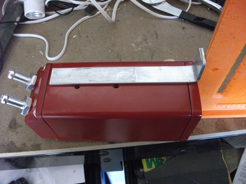
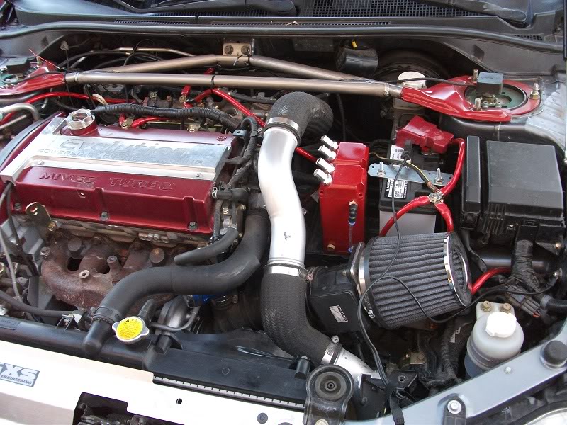
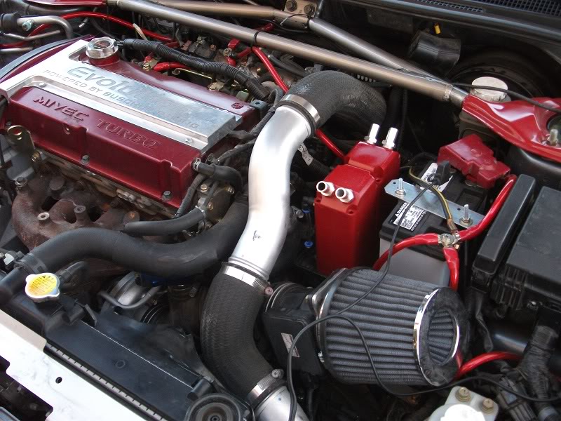
I used a common vice and bent the two brackets by hand, they fit quite well allowing me to attach both cans to the stock battery tray I still run. Perhaps in the future if I change out my upper pipe for a short route I will relocate the two cans but for now this worked out great.
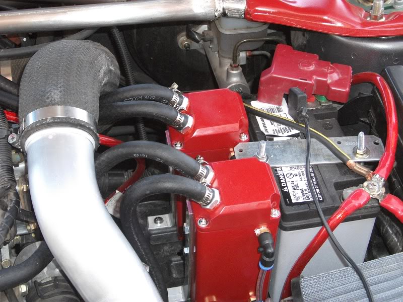
I routed all of the heater hose under the upper pipe, and under the front brace for ascetics.
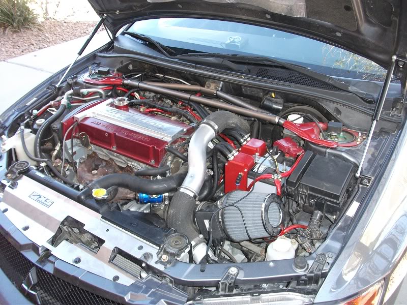
So far they are doing great, I did some pulls to verify that nothing blew off and that the hoses did not catch on anything. So far so good, it has pulled out a small amount of oil in the time it has been installed. Time shall tell how much more it can take.
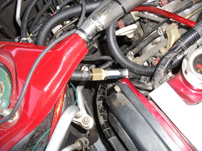
Originally I had used a 3/8 to 3/8 coupler between the hose leading from the intake manifold to the catch can and I left the PCV valve in the original location. I was informed that this was a bad idea, since when you are on boost the intake manifold will pressurize that line and force your catch can to pressurize to about boost PSI. While this is not horrible it is not a great situation as you can open yourself up to boost leaks. I replaced the 3/8 to 3/8 coupler with a slightly jerry rigged (since I could not find the right fittings) PCV valve to 1/8 NPT to 3/8 NPT coupler to a 3/8NPT to 3/8 ID Hose coupler. I was trying to find a 1/8 NPT to 3/8 coupler to connect to the hose but I was not able to find one at Lowes, oh well. To make things easier for myself I reused the factory hose, and installed my new '3/8 to 3/8 PCV valve' into the factory hose, then connected it to the outlet of the catch can. This will allow proper venting, and stop pressure from entering the catch can. I would like to thank Appauldd and tkklemann for bringing this to my attention. Remember to install the PCV in the same direction as from the factory! The PCV valve should be inserted into the hose going to the intake manifold with the threaded side pointed towards the catch can. You can also elect to replace the connector going to the catch can with the PCV valve as well, I personally liked the nice even look and I figured this way the pressurized length of tubing would be identical to stock.
Here is a little connection diagram to show where all the points are:
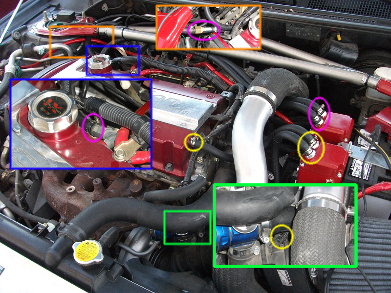
The Yellow circles all connect together through one can, and the purple through the other. You will be going from the Valve covers to the inlet port on your catch can to either the intake just past the maf, or to the intake manifold.
You will notice on in the Orange square that I circled two points, one is underneath on the intake manifold, I had a hard time trying to get at it so I just used the coupler and connected to the stock line after I removed the other end from the PCV valve. Hence the second wider oval.
The line going to the intake was also somewhat hard to get at, I had to partially remove the UICP and disconnect the BoV/DV to have easier access.
Just remember the ports connecting to the intake track be it in the intake tube before the turbo or on the intake manifold are connected to the outlet tubes (the ones that do not have the copper tube attached internally). =)
Cans: $53
2 - 'eBay' Greddy/Megan Style Catch Cans - $48 shipped
1/8" X 3/4" - 18 inches or so inch aluminum - $5 Lowes
4 Screws to connect the cans to the mount. On these ebay cans they were 6mm-1.0x10mm - Had them from another project
Baffle Modification: $6.50
1ft of 3/8" copper tube - $cheap at Home Depot. I want to say $3.
3/8 to 3/8 copper 45 degree coupler - $1.50 at Lowes
Stainless Steel scouring pad - $2 Albertsons racing
Hose/Coupler: $12
3/8th fuel hose 8 feet - $10 O'Riely Auto
3/8 to 3/8 hose coupler (optional) - $2 O'Riely Auto (brass was all they had, the plastic ones should work, be cheaper and do the same job)
Total project cost - approximately $71.5 + a couple of screws and washers I had.
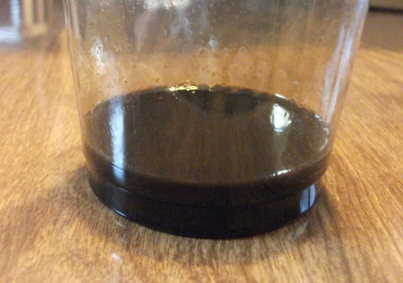
Update: I removed the catch cans today while I was changing out my UICP. The PCV side can caught quite a bit. The Intake side caught some as well, so I'm very glad to see them working! About 90% of what is in the glass is from the PCV side of things.
I hope you all enjoy this little DIY How To.
Edit: Updated information to reflect move of the PCV valve.
So I had been looking around to do a catch can mod since I switched out to a mini battery. After looking at all the aftermarket cans and reading up about them I found almost all of them had the same deficiency (in addition to being overpriced) almost none of them had any sort of baffling or even forced the air to go to the bottom of the tank before it exited. Sure they would work a little, but I know they would still let a decent amount of blow by thru.
At this point I started looking heavily into the DC3 catch can, but I did not have any great location to mount it, and it was just a little more than I wanted to spend.
So I decided to look on good old e-bay and see what they had to offer. After sifting through pages of them I came across these catch cans that appeared to have screws in them to allow me to open them up and mess with their innards. They also looked similar to Greddy/Megan catch cans and were made from aluminum so they would be decently light. So i ordered up a set of them in GUNMETAL and I received them in short order.
What a lovely shade of gunmetal eh? Well its eBay what can you expect, for just under $50 shipped for the 2 of them I couldn't complain much. I was going to attempt to strip them and just either polish them or give them a brushed look, but after seeing that the anodizing would require a stripper that was VERY toxic I deiced to just go at them with some spray paint. A note on disassembling these guys, they come with 3/8" and 3/4" nipples, and the tops and bottoms can be unscrewed. I would NOT recommend touching the bottom set of hex bolts, I had a horrible time getting one of the screws back in. The top ones came out and went back in very easily.
After opening it up I saw that of course there was nothing to them inside, just a hollow box with a clear tube on the side.
I ran out and purchased some aluminum to make a stand, some 'flexible' copper tubing (3/8" ID I believe), some scouring pads and 8 feet of 3/8" fuel hose (7' would have sufficed).
The Inner Diameter of these fittings were just slightly larger than what I needed so I put them in a vice, and increased the size of the hole to accept my copper tubing using my drill press. You could use a smaller copper tube but I had had a different idea which did not pan out so I was stuck with the size of tubing I bought.
My original design called for me to bend the tube to about a 45 degree angle, this slightly compressed the tube and was frankly a bit hard to do so after the first one I deiced to pick up a copper 45 degree coupler that I managed to find at Lowe's. You'll notice the fit was fairly tight even without any sort of bonding agent.
Once installed in the catch can it went almost all the way down, leaving a good one inch gap a the bottom. I connected the tubes to the aluminum in a somewhat questionable way, we'll see how it does over the long run. I decided to line the inside of the drilled out fitting with a thin layer of Red RTV Silicone I had for another project and also put a bead of it around the tube to seal it. It should hold since there should not really be any noticeable force hitting the tubes, but if it does fail I will look into alternatives. I could not screw in the fittings with the copper tubes attached so I did not want to attempt to solder the tubes in place.
At this point I made the second tube, and finished painting the cans with a high heat engine enamel. I now had the fun challenge of figuring out which direction I wanted the face the cans, originally I was going to face them both towards the motor but put the bottom on 180 degrees off of each other so I could press the 2 together. This caused a problem though since the mounting holes were going to be on opposite sides. I also thought about putting one can facing forward and one reverse, it had an interesting effect but in the end I scrapped that idea.
I picked up this piece of aluminum ($5) to make the mounts for the cans, they come with a small bracket but it was not going to be useful in my situation.
Here are the two different setups side by side, I prefer the one on the left, it was by far easier to do than trying to bend the tube and not crush it. I also had a brain fart when I was doing the cross drilling of the holes, I should have used my dowel centering jig but I did not and just tried to eyeball it on my drill press, it was somewhat of a pain, but they will serve their purpose if the can starts collecting a lot of oil.
These are the stainless steel pads I bought which come 2 in a bag, they are much coarser than steel wool and they are less prone to oxidation and breaking down, I don't want bits of metal to replace the drops of oil going into my intake track. I thought of some other baffling materials, but this was a reasonably priced offering that I think would do the trick. They come in this nice little ball shape, but you can easily work the material into this cylindrical torus shape, with a convent shaft down the middle to insert the copper tube. 1 pad fit quite nicely in the catch can so I used one in each.
I then proceeded to create the mounting bracket. Using my Dremel I cut the aluminum to 7.5" to allow for a 1.5" bottom anchor point. In this shot I bent it then I made the holes, I found it was easier to drill the 3 holes THEN bend it =).
I used a common vice and bent the two brackets by hand, they fit quite well allowing me to attach both cans to the stock battery tray I still run. Perhaps in the future if I change out my upper pipe for a short route I will relocate the two cans but for now this worked out great.
I routed all of the heater hose under the upper pipe, and under the front brace for ascetics.
So far they are doing great, I did some pulls to verify that nothing blew off and that the hoses did not catch on anything. So far so good, it has pulled out a small amount of oil in the time it has been installed. Time shall tell how much more it can take.
Originally I had used a 3/8 to 3/8 coupler between the hose leading from the intake manifold to the catch can and I left the PCV valve in the original location. I was informed that this was a bad idea, since when you are on boost the intake manifold will pressurize that line and force your catch can to pressurize to about boost PSI. While this is not horrible it is not a great situation as you can open yourself up to boost leaks. I replaced the 3/8 to 3/8 coupler with a slightly jerry rigged (since I could not find the right fittings) PCV valve to 1/8 NPT to 3/8 NPT coupler to a 3/8NPT to 3/8 ID Hose coupler. I was trying to find a 1/8 NPT to 3/8 coupler to connect to the hose but I was not able to find one at Lowes, oh well. To make things easier for myself I reused the factory hose, and installed my new '3/8 to 3/8 PCV valve' into the factory hose, then connected it to the outlet of the catch can. This will allow proper venting, and stop pressure from entering the catch can. I would like to thank Appauldd and tkklemann for bringing this to my attention. Remember to install the PCV in the same direction as from the factory! The PCV valve should be inserted into the hose going to the intake manifold with the threaded side pointed towards the catch can. You can also elect to replace the connector going to the catch can with the PCV valve as well, I personally liked the nice even look and I figured this way the pressurized length of tubing would be identical to stock.
Here is a little connection diagram to show where all the points are:
The Yellow circles all connect together through one can, and the purple through the other. You will be going from the Valve covers to the inlet port on your catch can to either the intake just past the maf, or to the intake manifold.
You will notice on in the Orange square that I circled two points, one is underneath on the intake manifold, I had a hard time trying to get at it so I just used the coupler and connected to the stock line after I removed the other end from the PCV valve. Hence the second wider oval.
The line going to the intake was also somewhat hard to get at, I had to partially remove the UICP and disconnect the BoV/DV to have easier access.
Just remember the ports connecting to the intake track be it in the intake tube before the turbo or on the intake manifold are connected to the outlet tubes (the ones that do not have the copper tube attached internally). =)
Cans: $53
2 - 'eBay' Greddy/Megan Style Catch Cans - $48 shipped
1/8" X 3/4" - 18 inches or so inch aluminum - $5 Lowes
4 Screws to connect the cans to the mount. On these ebay cans they were 6mm-1.0x10mm - Had them from another project
Baffle Modification: $6.50
1ft of 3/8" copper tube - $cheap at Home Depot. I want to say $3.
3/8 to 3/8 copper 45 degree coupler - $1.50 at Lowes
Stainless Steel scouring pad - $2 Albertsons racing
Hose/Coupler: $12
3/8th fuel hose 8 feet - $10 O'Riely Auto
3/8 to 3/8 hose coupler (optional) - $2 O'Riely Auto (brass was all they had, the plastic ones should work, be cheaper and do the same job)
Total project cost - approximately $71.5 + a couple of screws and washers I had.
Update: I removed the catch cans today while I was changing out my UICP. The PCV side can caught quite a bit. The Intake side caught some as well, so I'm very glad to see them working! About 90% of what is in the glass is from the PCV side of things.
I hope you all enjoy this little DIY How To.
Last edited by vortico; Jul 13, 2011 at 06:38 PM. Reason: Added results
 Apr 10, 2010, 09:08 PM
#3
Thanks for the comment Gordian79. The floor is a Quikrete epoxy paint. If you are going to do it be very very careful and thorough with using the stripper on the concrete. Any paint or oil that you leave will let it peel up. It took me around 4 rounds of the stripping/washing to get my concrete clean enough to do the paint. Take your time on that step or you will have to do it again when the paint peels.
 Apr 11, 2010, 07:04 PM
#7
Evolved Member
iTrader: (22)
Join Date: Nov 2003
Location: Northern KY near Cincy
Posts: 2,408
Likes: 0
Received 6 Likes
on
6 Posts
One suggestion.....move the PCV valve so that it connects to the catch can. This will prevent the catch can from pressurizing under boost.....well not prevent it completely, but certainly deter it.
Trending Topics
Apr 12, 2010, 06:28 AM
#8
Appauldd thanks for the suggestion, but I am not sure if I follow what you mean. Right now the PCV valve goes to the can, the other side of the can goes to the intake manifold. If you mean rotate the pcv 180 degrees so it points towards the can as opposed to away, I wanted to do that but I wasn't sure if I could without breaking the pcv valve. Is there a good way to rotate it?
Apr 12, 2010, 06:32 AM
#9
Evolved Member
iTrader: (22)
Join Date: Nov 2003
Location: Northern KY near Cincy
Posts: 2,408
Likes: 0
Received 6 Likes
on
6 Posts
In stock form the line goes from the intake to the PVC. You have it set up with the line going from the intake to your catch can, the out of the catch can and into the pcv. Thus you are pressurizing your catch can under boost.
SO..
Take the PCV off of the valve cover and mount it to the inlet side of your catch can. Then run a line from the outlet side of the catch can back to the valve cover.
SO..
Take the PCV off of the valve cover and mount it to the inlet side of your catch can. Then run a line from the outlet side of the catch can back to the valve cover.
Apr 12, 2010, 06:36 AM
#10
Evolved Member
iTrader: (6)
Join Date: Jul 2005
Location: Charleston, SC
Posts: 1,228
Likes: 0
Received 0 Likes
on
0 Posts
Appauldd thanks for the suggestion, but I am not sure if I follow what you mean. Right now the PCV valve goes to the can, the other side of the can goes to the intake manifold. If you mean rotate the pcv 180 degrees so it points towards the can as opposed to away, I wanted to do that but I wasn't sure if I could without breaking the pcv valve. Is there a good way to rotate it?
No, that's not what he means. You want the PCV inline with the line that comes off of your intake manifold. The way you have your cans set up, the rear can is being subjected to whatever amount of boost you are running. DO NOT ROTATE YOUR PCV VALVE! (Otherwise you will subject your crank-case to your full boost pressure.)
You basically want your PCV valve inbetween your catch can and the hose connected to the intake manifold. Just make sure that the nipple on the actual PCV valve is facing the intake manifold to keep boost pressure from pressurizing the catch can itself.
Apr 12, 2010, 06:37 AM
#11
Evolved Member
iTrader: (6)
Join Date: Jul 2005
Location: Charleston, SC
Posts: 1,228
Likes: 0
Received 0 Likes
on
0 Posts
In stock form the line goes from the intake to the PVC. You have it set up with the line going from the intake to your catch can, the out of the catch can and into the pcv. Thus you are pressurizing your catch can under boost.
SO..
Take the PCV off of the valve cover and mount it to the inlet side of your catch can. Then run a line from the outlet side of the catch can back to the valve cover.
SO..
Take the PCV off of the valve cover and mount it to the inlet side of your catch can. Then run a line from the outlet side of the catch can back to the valve cover.
Ack! Reply beat by 4 minutes... Oh well!
 Apr 12, 2010, 06:39 AM
#13
Evolved Member
iTrader: (6)
Join Date: Jul 2005
Location: Charleston, SC
Posts: 1,228
Likes: 0
Received 0 Likes
on
0 Posts
Appauldd thanks for the suggestion, but I am not sure if I follow what you mean. Right now the PCV valve goes to the can, the other side of the can goes to the intake manifold. If you mean rotate the pcv 180 degrees so it points towards the can as opposed to away, I wanted to do that but I wasn't sure if I could without breaking the pcv valve. Is there a good way to rotate it?
Buschur, not Bushur in your sig... FYI..
 Apr 12, 2010, 08:34 AM
#14
In stock form the line goes from the intake to the PVC. You have it set up with the line going from the intake to your catch can, the out of the catch can and into the pcv. Thus you are pressurizing your catch can under boost.
SO..
Take the PCV off of the valve cover and mount it to the inlet side of your catch can. Then run a line from the outlet side of the catch can back to the valve cover.
SO..
Take the PCV off of the valve cover and mount it to the inlet side of your catch can. Then run a line from the outlet side of the catch can back to the valve cover.
Oh and fixed the sig issue, swore I already had a long time ago but perhaps I was mistaken =). Thanks for pointing it out.
Edit: saw a decent diagram of what I was trying to do on that same thread listed above.

From the looks of it I see what you are saying with moving the actual PCV valve to the catch can, What would be the right way to move it without causing issues?
Last edited by vortico; Apr 12, 2010 at 08:37 AM.
Apr 12, 2010, 08:49 AM
#15
Evolved Member
iTrader: (22)
Join Date: Nov 2003
Location: Northern KY near Cincy
Posts: 2,408
Likes: 0
Received 6 Likes
on
6 Posts
There isn't really a "right way". Just un-screw the PCV from the valve cover and screw in a male hose connector. Then, thread in a female adapter into the catch and thread the PCV into the adapter. Reconnect your hose as it is now.
The main reason for this is to help avoid potential boost leaks. Sure they catch cans are "leak free" but doing this will certainly help.
The main reason for this is to help avoid potential boost leaks. Sure they catch cans are "leak free" but doing this will certainly help.

