How to Setup Tephramod V7
 Jan 5, 2013, 07:45 PM
#1
How to: Setup Tephramod V7 - ECU-based boost control guide
tutorial written by: Raptord, ReaperX, domyz... ... ...
(this is guide is still in development) If you feel there is something to be added or you are wanting to help, send me a PM.
See post #2 below for Raptord's TephraMod v7 ECU-based boost control guide.
Introduction
First we'd like to thanks “tephra”,”mrfred”,” and all people who've worked on this awesome ECU add-on. We lately had many questions from DIY tuners that were having trouble in various part of the conversion to V7, so we discussed about making a how-to. This guide will help you converting your old ROM to tephra V7 ROM and tweaking new features.
__________________________________________________ _____________
1-Know what ECU/Evo you have (Year, Model, USDM/JDM/EDM)
2-Download the ROM, and the XML Pack from this page
*Important: Read all the information from tephra in the above link
3-Extract the XML Pack to:
C:\Program Files\OpenECU\EcuFlash\rommetadata\mitsubishi\evo
(default location)
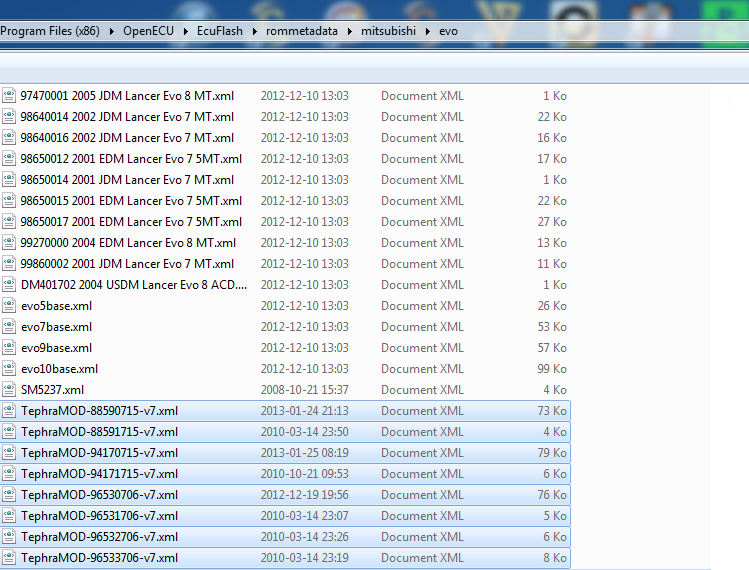
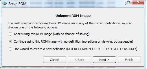
4-Open your new V7 ROM. If you get this message, your XML files are at the wrong location. Click Cancel and close Ecuflash. Then go back to step 3.
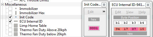
5-Copy all the maps from your old ROM to V7 ROM.
Leave these two tables untouched:
6- How to setup V7 Fuel and timing maps
1. Prior to converting to Tephra, ensure that you have a safe and conservative tune to work from as a base.
2. Do several logs of your factory rom tune for reference during the conversion.
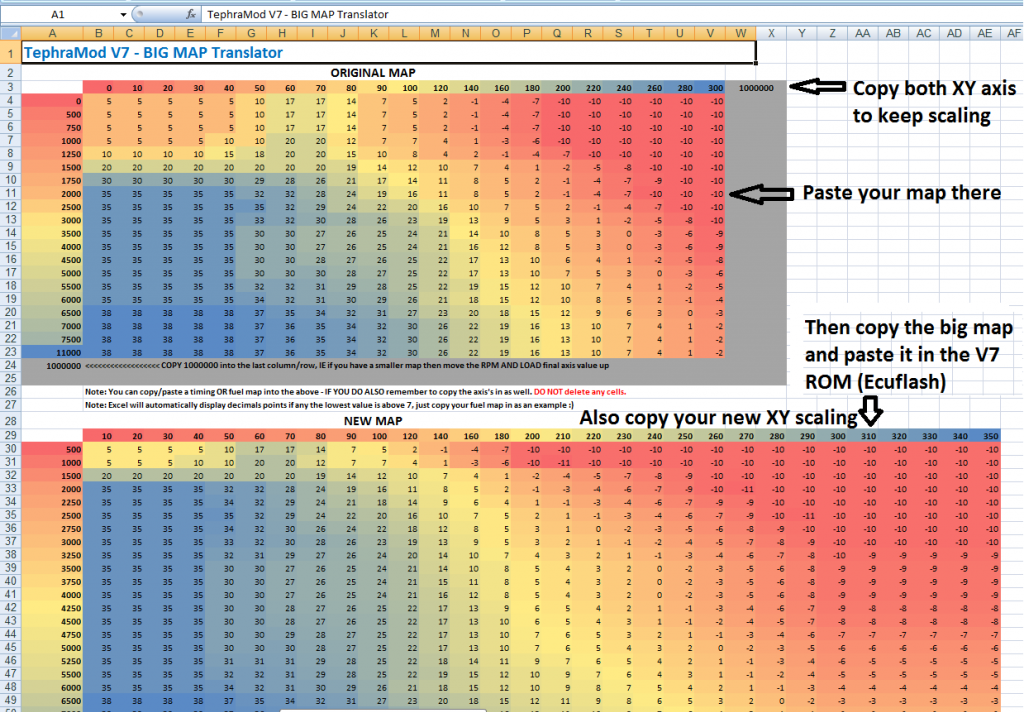
3. There are a few tools that will help you in the conversion. Tephra added resolution for these maps in his ROM. The first tool is the Big map translator (from tephra). When you open the excel file, you use the top section to copy your factory rom info into and the lower section will have your new Big Maps. Make sure that if you re-scaled values in the either axis of the factory rom that you also copy those into the axis of the top section of the Big Map Translator. The second tool is the Big Map Smoothing Tool, this will make it a lot easier to smooth your maps when finished tuning.
4. Now you’re ready to import you factory rom fuel and ignition maps into the Tephra rom.
5. Locate your high octane timing and fuel maps within your factory rom.
6. Copy high octane timing map into the Big Map Translator.
7. Copy results from the Big Map Translator into the High Octane Ignition Map under the Main Map Ignition Settings header.
8. Copy high octane fuel map into the Big Map Translator.
9. Copy results from the Big Map Translator in the High Octane Fuel Map under the Main Map Fuel Settings header.
10. Review your new big maps to ensure there are no load cells that increment-decrement-increment horizontally or vertically. An example would be if the timing map displayed 6*,5*,6* in the 200-210-220 load columns at 3000rpm’s. Adjust as needed for a smooth transition between load cells and rpm. The smoothing tool posted above will get rid of these "holes or jumps" in the timing map.
11. Copy your new big map high octane ignition map into the low octane ignition map under the same Main Map Ignition Settings header. Highlight the load areas of the map that are targeted during boost, greater than 100 load throughout the rev range. Decrement them by 3*-5* depending on your comfort level.
*Note: Even if you leave Low Octane and High octane maps the same, knock occurence will still pull 1* of timing per 3 knock counts. The low octane map is used when knock is consistent/ECU RAM octane number has decreased enough.
12. Copy your new big map high octane fuel map into the low octane fuel map under the same Main Map Fuel Settings header. Highlight the load areas of the map that are targeted during boost, greater than 100 load throughout the rev range. Decrement them to your comfort level. General rule is to be 1 point richer for the low octane map.
7-Setting up new V7 features
Great info there about the new features: http://evoecu.logic.net/wiki/TephraMod
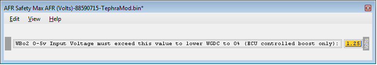
A note about AFR safety:
How to convert desired AFR to voltage ? Let's say you want AFR safety feature to activate at 12.5:1 AFR. The general formula is:
[(DesiredAFRSafety - WidebandMinAFR) / (WidebandMaxAFR- WidebandMinAFR)] * 5
8-Boost tuning
See post #2, Raptord's writeup.
tutorial written by: Raptord, ReaperX, domyz... ... ...
(this is guide is still in development) If you feel there is something to be added or you are wanting to help, send me a PM.
See post #2 below for Raptord's TephraMod v7 ECU-based boost control guide.
Introduction
First we'd like to thanks “tephra”,”mrfred”,” and all people who've worked on this awesome ECU add-on. We lately had many questions from DIY tuners that were having trouble in various part of the conversion to V7, so we discussed about making a how-to. This guide will help you converting your old ROM to tephra V7 ROM and tweaking new features.
__________________________________________________ _____________
1-Know what ECU/Evo you have (Year, Model, USDM/JDM/EDM)
2-Download the ROM, and the XML Pack from this page
*Important: Read all the information from tephra in the above link
3-Extract the XML Pack to:
C:\Program Files\OpenECU\EcuFlash\rommetadata\mitsubishi\evo
(default location)
4-Open your new V7 ROM. If you get this message, your XML files are at the wrong location. Click Cancel and close Ecuflash. Then go back to step 3.
5-Copy all the maps from your old ROM to V7 ROM.
Leave these two tables untouched:
6- How to setup V7 Fuel and timing maps
1. Prior to converting to Tephra, ensure that you have a safe and conservative tune to work from as a base.
2. Do several logs of your factory rom tune for reference during the conversion.
3. There are a few tools that will help you in the conversion. Tephra added resolution for these maps in his ROM. The first tool is the Big map translator (from tephra). When you open the excel file, you use the top section to copy your factory rom info into and the lower section will have your new Big Maps. Make sure that if you re-scaled values in the either axis of the factory rom that you also copy those into the axis of the top section of the Big Map Translator. The second tool is the Big Map Smoothing Tool, this will make it a lot easier to smooth your maps when finished tuning.
4. Now you’re ready to import you factory rom fuel and ignition maps into the Tephra rom.
5. Locate your high octane timing and fuel maps within your factory rom.
6. Copy high octane timing map into the Big Map Translator.
7. Copy results from the Big Map Translator into the High Octane Ignition Map under the Main Map Ignition Settings header.
8. Copy high octane fuel map into the Big Map Translator.
9. Copy results from the Big Map Translator in the High Octane Fuel Map under the Main Map Fuel Settings header.
10. Review your new big maps to ensure there are no load cells that increment-decrement-increment horizontally or vertically. An example would be if the timing map displayed 6*,5*,6* in the 200-210-220 load columns at 3000rpm’s. Adjust as needed for a smooth transition between load cells and rpm. The smoothing tool posted above will get rid of these "holes or jumps" in the timing map.
11. Copy your new big map high octane ignition map into the low octane ignition map under the same Main Map Ignition Settings header. Highlight the load areas of the map that are targeted during boost, greater than 100 load throughout the rev range. Decrement them by 3*-5* depending on your comfort level.
*Note: Even if you leave Low Octane and High octane maps the same, knock occurence will still pull 1* of timing per 3 knock counts. The low octane map is used when knock is consistent/ECU RAM octane number has decreased enough.
12. Copy your new big map high octane fuel map into the low octane fuel map under the same Main Map Fuel Settings header. Highlight the load areas of the map that are targeted during boost, greater than 100 load throughout the rev range. Decrement them to your comfort level. General rule is to be 1 point richer for the low octane map.
7-Setting up new V7 features
Great info there about the new features: http://evoecu.logic.net/wiki/TephraMod
A note about AFR safety:
How to convert desired AFR to voltage ? Let's say you want AFR safety feature to activate at 12.5:1 AFR. The general formula is:
[(DesiredAFRSafety - WidebandMinAFR) / (WidebandMaxAFR- WidebandMinAFR)] * 5
AEM Wideband |
Innovate LC1 Wideband (Analog output 2) |
| MinAFR=10 / MaxAFR=20 |
| [(12.5 - 10) / (20-10)] * 5 = 1.25 Volts |
8-Boost tuning
See post #2, Raptord's writeup.
tutorial written by: Raptord, ReaperX, domyz... ... ...
Last edited by domyz; Sep 20, 2019 at 05:17 PM.

The following 2 users liked this post by domyz:
EV09AWD (Oct 29, 2017),
Janimester (Oct 29, 2023)
Feb 6, 2013, 09:17 AM
#2
Raptord's TephraMod v7 ECU-based boost control guide
Version 0.12
Changelog:
Welcome to my Tephra v7 ecu-based boost control guide. If you have any suggestions, comments, questions that you feel I should answer in this guide that I haven't, or notice a mistake, please feel more than welcome to send me a PM.
There are already a number of guides explaining ECU boost control, however there are none specific to Tephra v7 and that seems to throw people off since the table names are different. Hopefully this guide will help clear things up for you. First we'll define some terms and concepts that will be used later in this guide.
Next we're going to take a look at some of the tables related to boost control. First up are some tables from the "Global Boost Control Settings" section. As the name suggests, these settings apply globally, whether you're on main or alt maps.
Now we'll get into the primary boost control tables. These are the tables you'll be playing with the most.
A note regarding the upward correction of the BEC table vs the Max Upward WGDC Correction vs TPS table
The upper half of the BEC table (the part where load/PSI is below the target) and the max upward currection table serve two different purposes, and zero-ing out one isn't the same thing as zero-ing out the other. Zero-ing out the upper half of the BEC table means that if the ECU lowers the WGDC because it had exceeded the target load or PSI, it won't be able to increase the WGDC by the same amount to cancel out that correction if load or boost go back below the desired levels. This is generally undesirable; you want the ECU to be able to cancel it's negative corrections if need be. Zero-ing out the Max upward correction table however, prevents the ECU from increasing WGDC beyond your base WGDC. This is good to prevent overboost during spoolup but also means if your base WGDC curve is too low for your targets, the ECU won't be able to compensate to reach them.
Example 1 with both the upper half of BEC and the Max upward correction table zero-ed out: Base WGDC is 50. Boost is too high, ECU lowers WGDC to 48. Now boost becomes too low. ECU can't do anything because it's not allowed to increase WGDC at all.
Example 2 with only Max upward correction zero-ed out: Base WGDC is 50. Boost is too high, ECU lowers WGDC to 48. Now boost becomes too low. ECU increases WGDC back to 50. Later in the pull, boost is too low again. The ECU doesn't increase WGDC because there are no more negative corrections to cancel.
Example 3 with neither table zero-ed out: Base WGDC is 50. During spoolup, ECU sees that boost is below the target, so it increases WGDC to 52. As the turbo finishes spooling, boost is now too high, so the ECU lowers WGDC to 49. Now boost becomes too low. ECU increases WGDC back to 50. Later in the pull, boost is too low again. The ECU increases WGDC to 51.
Now we'll get into the actual guide to setting your boost, setting your target PSI/load, and using correction to maintain those desired targets (last 2 being optional)
Part 1: Setting base WGDC
The first part of setting up ECU-controlled boost is setting up the BWGDC table to to reach the approximate target boost you're aiming for (be it a flat boost curve throughout the full RPM range, a conventional peak-and-tapper, or gradually increasing boost as RPM increases to limit torque at lower RPM).
Important: You'll need to make sure the right side of the BEC table is zero-ed out. We don't want the ECU messing around with WGDC just yet. Next you'll want to enter some conservative values in the BWGDC table. If you aren't sure where to start, then start at 10% and adjust from there. It's simply a matter of trial and error to get the bost curve you want; make WGDC change, reflash, log a pull in 3rd gear, check log, rinse and repeat.
Usually I start in 3rd gear. The WGDC settings I'll use for 1st and 2nd will be the same as the ones used for 3rd. 4th gear will be 1% lower than 3rd, and 5th will be another 1% lower. I then log as best I can to check that the boost in 4th and 5th is OK.
When you've got your BWGDC reasonably well dialed-in, you can either stop here and not use BEC at all, or continue with the next 2 parts to set up BEC.
Part 2: Set up boost (or load) targets
Parts 2 and 3 are not required but recommended in order to take full advantage of the possibilities offered by ECU-controlled boost.
The ECU needs an aftermarket MAP sensor to be able to read boost correctly. This is because our stock MAP sensors are only 1 bar sensors, which is about 14.7 PSI. If you still have the OEM MAP sensor and don't want to switch it, you won't be able to use PSI-based boost control, but you can use the load-based variant. Read on below after the PSI-based section for specific steps for load-controlled boost.
PSI-based vs load-based boost control
We can set our ECU to target either a specific boost (PSI), or a specific load. As in many things, both have their advantages and disadvantages. Personnally I use PSI-based boost control. I'll list the differences and let you make your pick.
PSI-based
{coming soon}
Load-based
{coming soon}
Setting up PSI-based boost control
With PSI-based boost control, we will tell the ECU what boost we want for each gear and at each RPM point. The ECU will then adjust WGDC to try and reach this boost.
The ECU calculates the target boost (the value in the ECU) and actual boost (what is physically going on) in the following ways:
Target boost = Boost Adder (PSI) + BDE (PSI)
Actual boost = atmospsheric pressure (henceforth referred to as PSIa) + positive boost pressure (what you see on your boost gauge)(henceforth referred to as PSIg)
The final result we're looking for is, of course, for our actual boost to follow our target boost. This would mean that:
Boost Adder (PSI) + BDE (PSI) = PSIa + PSIg
Each side of this equation has 2 variables. Looking at it differently however, we actually have 1 constant on each side: Boost Adder and PSIa. Boost Adder is a constant because it's a single value that we set in the ECU; it can never change. PSIa can be considered a constant because your local atmospheric pressure doesn't really change, unless you travel to places with large differences in elevation.
So, if we were to set Boost Adder (PSI) to be the same value as PSIa, we would be left with the following:
BDE (PSI) = PSIg
Or, in plain English; Whatever PSI value we enter in the BDE table for a given RPM and gear is the boost pressure on your boost gauge that the ECU will aim to reach.
Let's look at an example with actual numbers instead of variables: We want 24 PSI throughout the whole rpm range, for each gear. If our Boost Adder table is correctly set to compensate for PSIa, then all we have to do is set all values in the BDE table to 24. Now the ECU will target a positive boost pressure of 24 PSI.
Unfortunately however, values greater than 22.7 cannot be entered in the BDE table. This means that if your target boost is 22.7 PSI or lower, you'll be able to use the simple process of having Boost Adder be equal to PSIa like I detailed above. If you want more than 22.7 PSI, your boost adder table will need to be higher than just the equivalent of PSIa. I prefer to increase it in steps of 10, which makes setting the BDE table a bit simpler.
For example, for a desired boost of 25psi:
Boost Adder = 24.5 (PSIa of 14.5 + 10) and BDE = 15
I like this solution as it means all I have to do to figure out my real target boost in the BDE table is change the 1 in 15 to a 2. So I know I'll be targetting 25 PSI. If you're targetting 30+ PSI, you can add 20 to PSIa for the Boost Adder and mentally add 20 to the value in the BDE table to know the ECU's target boost. So to target 36 psi, you'd just enter 16 in the BDE table.
If you don't already have a "Boost Error" entry to log in evoscan, add the following to your evoscan xml:
Now that you've set your values in the ECU, time to verify that they are correct. Log a pull and ensure to have Boost Error checked. Boost Error can vary from -3 to +3. From the moment you reach peak boost, your boost error should be fairly close to 0. To see what the ECU thinks your target is, simply subtract boost error from the logged boost. For example, if logged boost is 26 and boost error is -1, we have 26 - (-1) = 27, which tells us the ECU's target was 27. If you were aiming for 27 psi, then you know your Boost Adder and BDE tables are set correctly. You're now ready for part 3.
Part 3: Set up Boost Error Correction (BEC)
Now that we're reaching the appoximate boost we want in each gear and the ECU knows what our target boost is, it's time to allow the ECU to adjust WGDC by itself in order to maintain that target boost. This is quite simple; all you need to set up is the BEC table.
The BEC table tells the ECU what adjustment to make to WGDC for a given boost error. If our boost is below our target, boost error will be negative. If boost is above our target, boost error will be positive. This means that for negative boost error we want to increase WGDC (in order for boost to reach our desired target), and for positive boost error we want to decrease WGDC (to bring boost back down to our target). The values you need to enter in your BEC table depend on the values you are using in the WGDC Correction Interval table. If your WGDC correction interval is set very low, and your BEC table is set to make large corrections, the ECU will end up constantly over-compensating, which will result in you being over your desired boost, then under it, then over again, and so on.
When you've decided on correction settings you want to use, log a few pulls and verify that the ECU is correctly adjusting WGDC to following your target boost.
Final notes
- As temperature changes, you may need to adjust the WGDC vs IAT table to keep your boost where you want it.
Version 0.12
Changelog:
| Date | Comments | Version |
| Feb. 6th 2013 | Initial release | 0.1 |
| Feb. 18th 2013 | Added code to add Boost Error to evoscan datalist | 0.11 |
| Oct. 19th 2013 | Added note regarding the BEC table and Max total upward correction | 0.12 |
Welcome to my Tephra v7 ecu-based boost control guide. If you have any suggestions, comments, questions that you feel I should answer in this guide that I haven't, or notice a mistake, please feel more than welcome to send me a PM.
There are already a number of guides explaining ECU boost control, however there are none specific to Tephra v7 and that seems to throw people off since the table names are different. Hopefully this guide will help clear things up for you. First we'll define some terms and concepts that will be used later in this guide.
Next we're going to take a look at some of the tables related to boost control. First up are some tables from the "Global Boost Control Settings" section. As the name suggests, these settings apply globally, whether you're on main or alt maps.
 | Boost Error Correction (BEC) (load and PSI) : These tables control how the WGDC will be adjusted to maintain the desired boost (or load, depending on which boost control method is being used). The column on the left is boost error. The right column tells you what correction will be applied to WGDC for a given boost error value. Shown is the PSI-based BEC table, but the load-based table works the same way, except that instead of checking actual boost vs target boost, the ECU will check actual load vs target load. In this image the error correction is disabled. |
 | WGDC=100% under this Load : This table is used to improve spool, at the expense of part-throttle driveability. With the stock value (200), it means that the WGDC will be locked at 100% until 200 load. After it crosses that treshold, the resto f the ECU's boost control routines will take over (IAT compensation, TPS compensation, Error correction, etc). The downside for part-throttle driveability is the following: Suppose you are using JUST enough throttle to reach 200 load with 100% WGDC. As soon as you reach that 200 load, the 100% WGDC table stops being in effect, and the rest of the ECU's boost control will kick in. This will generally result in a final WGDC different than 100% (for example, we'll take 60%). 60% WGDC doesn't spool the turbo as much as 100% WGDC, and your throttle was only barely open enough to reach 200 load when WGDC was at 100%. Now that it's at 60%, the turbo slows down a bit and you fall back down under 200 load. Now that you're below 200 load, the "WGDC=100% under this Load" will kick in again, bringing WGDC back to 100%. Now you go up past 200 load again, and the cycle repeats. This rapid cycling around 200 load causes jerking and makes partial-boost difficult to attain; you either need to make sure you stay under your load threshold so the table doesn't get deactivated, or you need to give enough throttle to pass the threshold and still have enough WGDC afterwards to stay above it. For people who road-race or autocross then, you may want to keep this disabled (put it at 0) to be able to smoothly apply throttle. On cars that see the drag strip or if you simply want the fastest possibly spool, you'll want this enabled. You'll need to test to make sure you don't put the treshold to close to your peak load, otherwise you may overshoot it. |
 | MAF IAT WGDC Correction : This table adjusts WGDC based on the intake air temperature (IAT). Colder air is denser, so if the WGDC stays the same for the full range of IATs, you will overboost when the temperature is below the one at which your tuned your boost. Inversely, you will see a lower boost than what you tuned for when it is warmer than when you did your tuning. This table will allow you to compensate for this. |
 | TPS WGDC Correction : This table adjusts WGDC based on current throttle position (TPS). I believe this correction is applied after others like IAT correction. This table makes the throttle even more progressive under partial throttle. For example, if the base WGDC was 60% for a given RPM and gear, but I'm at 75% TPS, the final WGDC (assuming there was no IAT or other corrections on this base number) will be 89% of 60, which is ~53%. You will sacrifice a tiny amount of spool since WGDC will be lower during the time it takes you to go from partial thorttle to WOT. |
 | Max Total Upward WGDC Correction vs TPS : This is the maximum correction beyond base WGDC that the ECU can apply when using BEC. While allowing some upward correction ensures that the ECU has the flexibility to increase WGDC to reach your target boost/load level, using this table also has a downside: When the turbo is spooling up, just before you reach target boost the ECU will see that you are below your target and will increase the WGDC by a couple of points since it thinks you're below your target, when in fact you're simply still in the process of spooling up. The result is that you can have some overboost until the ECU sees that you're now above target boost, and takes that extra WGDC back off. |
Now we'll get into the primary boost control tables. These are the tables you'll be playing with the most.
 | Main Map Wastegate Duty (base WGDC, BWGDC) : This is the most important table for ECU-controlled boost. This sets the base WGDC for each given gear and RPM point. (We call it the "base" WGDC because this value will be modified by other tables such as IAT compensation, etc in order to obtain the "final" WGDC, and also by boost error correction when it is enabled). As mentioned above, higher WGDC gives higher boost. |
 | Boost Desired Engine 'PSI'/'load' (BDE) : These two tables ('load' and 'PSI') are used to set your target boost/load for each gear and RPM point, in addition to the Boost Adder table below |
 | Boost Adder (PSI)/(LOAD) : Along with the BDE table, these tables are used to allow you to reach higher target boost/load targets and to compensate for atmospheric pressure (more on that later). |
A note regarding the upward correction of the BEC table vs the Max Upward WGDC Correction vs TPS table
The upper half of the BEC table (the part where load/PSI is below the target) and the max upward currection table serve two different purposes, and zero-ing out one isn't the same thing as zero-ing out the other. Zero-ing out the upper half of the BEC table means that if the ECU lowers the WGDC because it had exceeded the target load or PSI, it won't be able to increase the WGDC by the same amount to cancel out that correction if load or boost go back below the desired levels. This is generally undesirable; you want the ECU to be able to cancel it's negative corrections if need be. Zero-ing out the Max upward correction table however, prevents the ECU from increasing WGDC beyond your base WGDC. This is good to prevent overboost during spoolup but also means if your base WGDC curve is too low for your targets, the ECU won't be able to compensate to reach them.
Example 1 with both the upper half of BEC and the Max upward correction table zero-ed out: Base WGDC is 50. Boost is too high, ECU lowers WGDC to 48. Now boost becomes too low. ECU can't do anything because it's not allowed to increase WGDC at all.
Example 2 with only Max upward correction zero-ed out: Base WGDC is 50. Boost is too high, ECU lowers WGDC to 48. Now boost becomes too low. ECU increases WGDC back to 50. Later in the pull, boost is too low again. The ECU doesn't increase WGDC because there are no more negative corrections to cancel.
Example 3 with neither table zero-ed out: Base WGDC is 50. During spoolup, ECU sees that boost is below the target, so it increases WGDC to 52. As the turbo finishes spooling, boost is now too high, so the ECU lowers WGDC to 49. Now boost becomes too low. ECU increases WGDC back to 50. Later in the pull, boost is too low again. The ECU increases WGDC to 51.
Now we'll get into the actual guide to setting your boost, setting your target PSI/load, and using correction to maintain those desired targets (last 2 being optional)
Part 1: Setting base WGDC
The first part of setting up ECU-controlled boost is setting up the BWGDC table to to reach the approximate target boost you're aiming for (be it a flat boost curve throughout the full RPM range, a conventional peak-and-tapper, or gradually increasing boost as RPM increases to limit torque at lower RPM).
Important: You'll need to make sure the right side of the BEC table is zero-ed out. We don't want the ECU messing around with WGDC just yet. Next you'll want to enter some conservative values in the BWGDC table. If you aren't sure where to start, then start at 10% and adjust from there. It's simply a matter of trial and error to get the bost curve you want; make WGDC change, reflash, log a pull in 3rd gear, check log, rinse and repeat.
Usually I start in 3rd gear. The WGDC settings I'll use for 1st and 2nd will be the same as the ones used for 3rd. 4th gear will be 1% lower than 3rd, and 5th will be another 1% lower. I then log as best I can to check that the boost in 4th and 5th is OK.
When you've got your BWGDC reasonably well dialed-in, you can either stop here and not use BEC at all, or continue with the next 2 parts to set up BEC.
Part 2: Set up boost (or load) targets
Parts 2 and 3 are not required but recommended in order to take full advantage of the possibilities offered by ECU-controlled boost.
The ECU needs an aftermarket MAP sensor to be able to read boost correctly. This is because our stock MAP sensors are only 1 bar sensors, which is about 14.7 PSI. If you still have the OEM MAP sensor and don't want to switch it, you won't be able to use PSI-based boost control, but you can use the load-based variant. Read on below after the PSI-based section for specific steps for load-controlled boost.
PSI-based vs load-based boost control
We can set our ECU to target either a specific boost (PSI), or a specific load. As in many things, both have their advantages and disadvantages. Personnally I use PSI-based boost control. I'll list the differences and let you make your pick.
PSI-based
{coming soon}
Load-based
{coming soon}
Setting up PSI-based boost control
With PSI-based boost control, we will tell the ECU what boost we want for each gear and at each RPM point. The ECU will then adjust WGDC to try and reach this boost.
The ECU calculates the target boost (the value in the ECU) and actual boost (what is physically going on) in the following ways:
Target boost = Boost Adder (PSI) + BDE (PSI)
Actual boost = atmospsheric pressure (henceforth referred to as PSIa) + positive boost pressure (what you see on your boost gauge)(henceforth referred to as PSIg)
The final result we're looking for is, of course, for our actual boost to follow our target boost. This would mean that:
Boost Adder (PSI) + BDE (PSI) = PSIa + PSIg
Each side of this equation has 2 variables. Looking at it differently however, we actually have 1 constant on each side: Boost Adder and PSIa. Boost Adder is a constant because it's a single value that we set in the ECU; it can never change. PSIa can be considered a constant because your local atmospheric pressure doesn't really change, unless you travel to places with large differences in elevation.
So, if we were to set Boost Adder (PSI) to be the same value as PSIa, we would be left with the following:
BDE (PSI) = PSIg
Or, in plain English; Whatever PSI value we enter in the BDE table for a given RPM and gear is the boost pressure on your boost gauge that the ECU will aim to reach.
Let's look at an example with actual numbers instead of variables: We want 24 PSI throughout the whole rpm range, for each gear. If our Boost Adder table is correctly set to compensate for PSIa, then all we have to do is set all values in the BDE table to 24. Now the ECU will target a positive boost pressure of 24 PSI.
Unfortunately however, values greater than 22.7 cannot be entered in the BDE table. This means that if your target boost is 22.7 PSI or lower, you'll be able to use the simple process of having Boost Adder be equal to PSIa like I detailed above. If you want more than 22.7 PSI, your boost adder table will need to be higher than just the equivalent of PSIa. I prefer to increase it in steps of 10, which makes setting the BDE table a bit simpler.
For example, for a desired boost of 25psi:
Boost Adder = 24.5 (PSIa of 14.5 + 10) and BDE = 15
I like this solution as it means all I have to do to figure out my real target boost in the BDE table is change the 1 in 15 to a 2. So I know I'll be targetting 25 PSI. If you're targetting 30+ PSI, you can add 20 to PSIa for the Boost Adder and mentally add 20 to the value in the BDE table to know the ECU's target boost. So to target 36 psi, you'd just enter 16 in the BDE table.
If you don't already have a "Boost Error" entry to log in evoscan, add the following to your evoscan xml:
Code:
<DataListItem DataLog="Y" Color="" Display="Boost Error" LogReference="BoostError" RequestID="8A" Eval="0.0241*x-3.087" Unit="psi" MetricEval="" MetricUnit="" ResponseBytes="1" GaugeMin="-5" GaugeMax="5" ChartMin="-5" ChartMax="5" ScalingFactor="1" Notes="" Priority="1" Visible="false" />
Part 3: Set up Boost Error Correction (BEC)
Now that we're reaching the appoximate boost we want in each gear and the ECU knows what our target boost is, it's time to allow the ECU to adjust WGDC by itself in order to maintain that target boost. This is quite simple; all you need to set up is the BEC table.
The BEC table tells the ECU what adjustment to make to WGDC for a given boost error. If our boost is below our target, boost error will be negative. If boost is above our target, boost error will be positive. This means that for negative boost error we want to increase WGDC (in order for boost to reach our desired target), and for positive boost error we want to decrease WGDC (to bring boost back down to our target). The values you need to enter in your BEC table depend on the values you are using in the WGDC Correction Interval table. If your WGDC correction interval is set very low, and your BEC table is set to make large corrections, the ECU will end up constantly over-compensating, which will result in you being over your desired boost, then under it, then over again, and so on.
When you've decided on correction settings you want to use, log a few pulls and verify that the ECU is correctly adjusting WGDC to following your target boost.
Final notes
- As temperature changes, you may need to adjust the WGDC vs IAT table to keep your boost where you want it.
Last edited by Raptord; Oct 19, 2013 at 01:50 PM.
The following 5 users liked this post by Raptord:
chvlleguy (Jun 22, 2019),
GrumpyIX (Nov 26, 2019),
Janimester (Oct 29, 2023),
Pal215 (Feb 2, 2023),
Rpf1evolution (Jan 6, 2023)

 Subscribed for up-dates
Feb 6, 2013, 09:56 AM
Subscribed for up-dates
Feb 6, 2013, 09:56 AM
#4
Thanks Raptord that's great. It's a nice write-up and that info was missing from EvoM. When you know what you're doing, you can avoid wasting time by doing many trial and error
I'll try to do some progress tonight about V7 features and post them up.
I'll try to do some progress tonight about V7 features and post them up.
Last edited by domyz; Aug 10, 2014 at 03:10 PM.
Trending Topics
 Mar 11, 2013, 08:02 PM
#9
can someone explain to me how this actually helps? if it is adjusting for you to the newer bigger maps wouldnt you need to basically retune the extra cells? for example to help you understand what im talking about if i took and directly copied in my map from a standard rom to the big maps, and just left them that way, anything in between lets say 300 load and 350 load the ecu will take the two cells and make a guess between the two. so if both are 10.0 the ecu will aim for 10.0 at any load between the two. now if i put it in the big map translator, and translate it into the big map, now it has 310 320 330 340 and 350, but all of them are still at 10.0 since it translated everything between the two cells. so what is the difference lol? and would you need to retune the whole map and tweak it all to be alot smoother. i ask because when i did this, i get a lot of blocked cells (cells with the same numbers) especially when i do the timing.
Mar 12, 2013, 07:09 AM
#10
With having more cells to work with, you can have smaller steps between your load and rpm increments, allowing you to have smoother transitions and more control. Also, people running big turbos benefit from larger maps since they don't need to lose resolution at cruise loads to be able to map for the very high loads they can reach.
Mar 12, 2013, 05:30 PM
#11
im guessing without running a very large turbo this will not be very beneficial to me then. my standard rom fuel and timing maps are pretty smooth, so when i plug them into this map translator i get a huge block of the same timing and fuel if that makes since.
Mar 12, 2013, 05:53 PM
#12
Example….say ur current load brk point end in the form of 300 to 340 so not much room for fine tuning if you wanted to trouble shoot a lean spot at 320 load and 7k rpm…..with the bigger map u will be able to do so since the brk points are now more visible/accessible so u can tune what’s in between 300 and 340 without having to rely on the ECU to interpolate. Hope that makes sense!
Mar 12, 2013, 08:35 PM
#14
Bigger map = more break points = more opportunity to fine tune the cells!
Example�.say ur current load brk point end in the form of 300 to 340 so not much room for fine tuning if you wanted to trouble shoot a lean spot at 320 load and 7k rpm�..with the bigger map u will be able to do so since the brk points are now more visible/accessible so u can tune what�s in between 300 and 340 without having to rely on the ECU to interpolate. Hope that makes sense!
Example�.say ur current load brk point end in the form of 300 to 340 so not much room for fine tuning if you wanted to trouble shoot a lean spot at 320 load and 7k rpm�..with the bigger map u will be able to do so since the brk points are now more visible/accessible so u can tune what�s in between 300 and 340 without having to rely on the ECU to interpolate. Hope that makes sense!
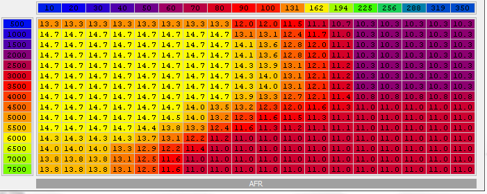
regular fuel map
Attachment 203307
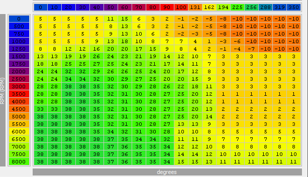
regular timing mapAttachment 203308
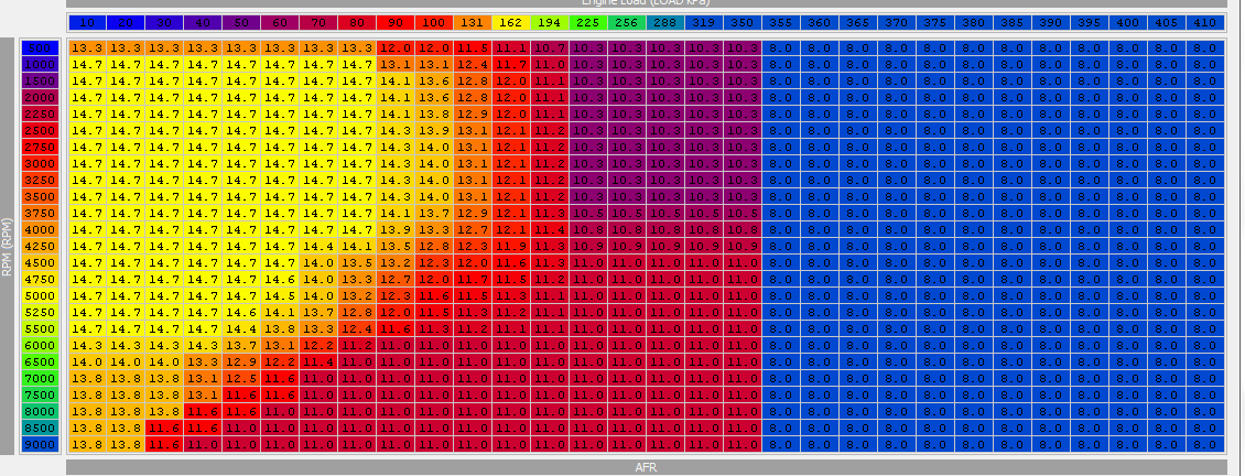
and now if i translate those into the big maps the areas of blocked tuning gets huge.
v7 big map fuel
Attachment 203309
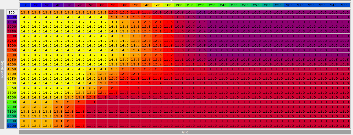
v7 big map timing
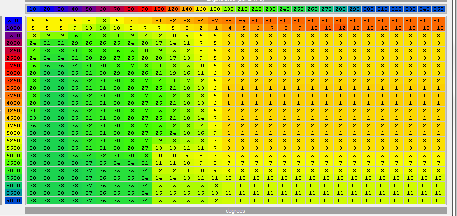
now, wouldnt doing this, and leaving it like that and flashing it basically be the same thing if i just copied my small map over into v7 like this? the ecu is already interpolating the areas between the cells and if both cells are 2* timing the ecu thinks well 2* timing between these numbers. if i translate it over now it has a huge area of 2* timing lol.