How-To: Super Fantastic JDM HVAC Swap
 Jan 17, 2016, 10:55 PM
#1

How-To: Super Fantastic JDM HVAC Swap
EVOLUTION AUTOMATIC CLIMATE CONTROL SWAP
AKA "THE BITCHIN' JDM SWAP"
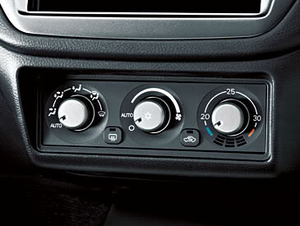
Table of Contents
Overview
The objective of this entire procedure is to get rid of the not only ugly, but also extremely dated climate control setup that was lovingly installed by Mitsubishi in all USDM Evolutions. This also allows for the easy relocation of climate controls to the lower cubby area and the installation of a storage pocket and a single-DIN radio or a double-DIN radio in the upper area.
Because the servo motors that control the air box are all inter-connected and adjust themselves using various sensors of different types, this is not a straight-forward swap like many people think it is. I will make it as simple as possible but you need to be comfortable with wiring to get this project done efficiently.
The JDM system consists of an A/C ECU which is the brain of the unit. Connected to it are three servo motors; one for the Air Mix portion of the heater box (this controls how warm the air flowing through the car is), the second is for the Mode portion of the heater box (this controls where the air is flowing to such as hands, face, or defrost), the final is for controlling the recirculation portion (whether the air coming into the heater box is from inside or outside the car). There are also sensors connected to the A/C ECU as well; one for monitoring the temperature of the air coming into the heater box, one for monitoring the temperature of the water in the heater core, one for monitoring the temperature of the air outside the car, one for monitoring the temperature of the air inside the car, and one for monitoring the amount of sunlight the car is experiencing. By combining inputs from these five sensors the A/C ECU is able to, if selected, automatically control the temperature inside the car and regulate it to the best of its ability.
I am doing this swap not for the automatic abilities of the unit, but because it looks much better and is more modern. Some people think the Evolution is a race car and doesn't deserve creature comforts, I personally think Mitsubishi are idiots for not including cruise control on a car built in the 21st Century.
This isn't for the faint of hearted. If you don't know your way around wiring and reading wiring diagrams (this not so much as I've written everything out), then do some research. I can't hold your hand through this process any more than answering questions that might arise.
Tips, Tricks, and Useful Information
Connectors
The connectors listed below are the most important connectors in this setup. These are going to be the ones I will refer to many times by connector number as opposed to "the 20-pin connector for the A/C ECU" as that would get extremely confusing.
This is a hard process to describe. If you're unsure at all,
will give you a decent idea what's going on behind the scenes.
In our case, the only connectors we will be de-pinning are C-17, C-18, and C-18 "OLD". All other connectors used will be used as pigtails and we will be snipping and soldering associated wires that are used with them
To de-pin C-17, C-18, and C-18 "OLD" you will need to slide the white inner shell "up". If you look closely at the back of the connector (where the wires protrude from) you will see tiny teeth that interlock between the white inner casing and the black outer casing. You will need to separate the outer casing far enough from the inner casing to unlock these teeth and slide the white inner casing toward the top of the connector. I did this by inserting my push-pins into the top-most teeth on the white casing, one on each side, and that was enough.
De-pinning Connectors Example 1 De-pinning Connectors Example 2
To remove the terminals from the connector, you'll need to lift the securing tooth on the top side of the pin and slide the pin out. This is difficult without knowing how to do it. What I did was slide the push-pin along the top of the connector until you feel it make contact (with the securing tooth), then push down on the push-pin to lift the pin inside the connector (like a lever) while simulatenously gently pulling on the associated wire. Pull too hard and the pin will have enough friction to not allow you to lift the securing tooth out of the way.
Tools Needed
These are optional in the sense that they allow easy removal of the heater wiring harness from the car if need be
Parts Needed
The Mode Motor, Air/Mix Motor, and Heater Blower Motor need to be from a Left-Hand Drive car! These specific parts sourced from a Right-Hand Drive car will not work!
All control motors and sensors that are not currently existing in the car will also need their associated connectors. Please take note of this when sourcing parts!
Notes:
Wiring Diagram for JDM Automatic Climate Control
JDM Wiring on Dropbox
Page 3-96
Page 3-97
Page 3-98
Page 3-99
Page 3-100
Page 3-101
Page 3-102
Wiring Diagram for USDM Manual Climate Control
USDM Wiring on Dropbox
Page 90-86
Page 90-87
Page 90-88
Page 90-89
Page 90-90
Wiring Preparation Work
Connector De-Pinning
Depin the following pins:
Wire Runs You'll Need to Create
Modified Wiring Harness Diagram
A/C ECU Harness Diagram
I'll make this up later
C-17 Connector
C-18 Connector
NOTES: THESE ARE IMPORTANT
Connectors that ground to C-17 (20):
AKA "THE BITCHIN' JDM SWAP"

Table of Contents
Overview
The objective of this entire procedure is to get rid of the not only ugly, but also extremely dated climate control setup that was lovingly installed by Mitsubishi in all USDM Evolutions. This also allows for the easy relocation of climate controls to the lower cubby area and the installation of a storage pocket and a single-DIN radio or a double-DIN radio in the upper area.
Because the servo motors that control the air box are all inter-connected and adjust themselves using various sensors of different types, this is not a straight-forward swap like many people think it is. I will make it as simple as possible but you need to be comfortable with wiring to get this project done efficiently.
The JDM system consists of an A/C ECU which is the brain of the unit. Connected to it are three servo motors; one for the Air Mix portion of the heater box (this controls how warm the air flowing through the car is), the second is for the Mode portion of the heater box (this controls where the air is flowing to such as hands, face, or defrost), the final is for controlling the recirculation portion (whether the air coming into the heater box is from inside or outside the car). There are also sensors connected to the A/C ECU as well; one for monitoring the temperature of the air coming into the heater box, one for monitoring the temperature of the water in the heater core, one for monitoring the temperature of the air outside the car, one for monitoring the temperature of the air inside the car, and one for monitoring the amount of sunlight the car is experiencing. By combining inputs from these five sensors the A/C ECU is able to, if selected, automatically control the temperature inside the car and regulate it to the best of its ability.
I am doing this swap not for the automatic abilities of the unit, but because it looks much better and is more modern. Some people think the Evolution is a race car and doesn't deserve creature comforts, I personally think Mitsubishi are idiots for not including cruise control on a car built in the 21st Century.
This isn't for the faint of hearted. If you don't know your way around wiring and reading wiring diagrams (this not so much as I've written everything out), then do some research. I can't hold your hand through this process any more than answering questions that might arise.
Tips, Tricks, and Useful Information
Connectors
The connectors listed below are the most important connectors in this setup. These are going to be the ones I will refer to many times by connector number as opposed to "the 20-pin connector for the A/C ECU" as that would get extremely confusing.
- Connector C-17 is a 20-pin connector that plugs into the back of the JDM A/C ECU
- Connector C-18 is a 16-pin connector that plugs into the back of the JDM A/C ECU
- Connector C-18 "OLD" is a 16-pin connector that plugs into the back of the USDM Climate Controls
- Connector C-03 is a 7-pin connector that plugs into the Air Exchange Motor
- Connector C-08 is a 6-pin connector that plugs into the Air Mix Motor
- Connector C-09 is a 2-pin connector that plugs into the Heater Water Temperature Sensor
- Connector C-10 is a 6-pin connector that plugs into the Air Mode Motor
- Connector C-28 is a 6-pin connector that plugs into the Heater Blower Motor
This is a hard process to describe. If you're unsure at all,
In our case, the only connectors we will be de-pinning are C-17, C-18, and C-18 "OLD". All other connectors used will be used as pigtails and we will be snipping and soldering associated wires that are used with them
To de-pin C-17, C-18, and C-18 "OLD" you will need to slide the white inner shell "up". If you look closely at the back of the connector (where the wires protrude from) you will see tiny teeth that interlock between the white inner casing and the black outer casing. You will need to separate the outer casing far enough from the inner casing to unlock these teeth and slide the white inner casing toward the top of the connector. I did this by inserting my push-pins into the top-most teeth on the white casing, one on each side, and that was enough.
De-pinning Connectors Example 1 De-pinning Connectors Example 2
To remove the terminals from the connector, you'll need to lift the securing tooth on the top side of the pin and slide the pin out. This is difficult without knowing how to do it. What I did was slide the push-pin along the top of the connector until you feel it make contact (with the securing tooth), then push down on the push-pin to lift the pin inside the connector (like a lever) while simulatenously gently pulling on the associated wire. Pull too hard and the pin will have enough friction to not allow you to lift the securing tooth out of the way.
Tools Needed
- #2 Phillips Screwdriver
- 10MM Socket Wrench
- 12MM Socket Wrench
- Extensions for the Socket Wrench
- Wire Cutters
- Wire Strippers
- Soldering Iron
- Heat Gun / Lighter for Heat Shrink Wrap
- Assorted Sizes of Heat Shrink Wrap
- 10' 14AWG Wire
- 50' 20AWG Wire
- Electrical Tape
- Connector Pin Removal Tools (I used Push-Pins)
These are optional in the sense that they allow easy removal of the heater wiring harness from the car if need be
- 1x 10-Way Automotive Connector
- 1x 4-Way Automotive Connector
- 1x 1-Way Automotive Connector
- Terminal Crimping Tool
Parts Needed
The Mode Motor, Air/Mix Motor, and Heater Blower Motor need to be from a Left-Hand Drive car! These specific parts sourced from a Right-Hand Drive car will not work!
All control motors and sensors that are not currently existing in the car will also need their associated connectors. Please take note of this when sourcing parts!
| Item | Part Number | Alt Part Number | Image | Notes |
| Heater Control Unit | MR513281 | MR979535 | MR513281, MR979535 | MR513281 has black knobs, MR979535 has silver knobs; I can't find the part number for the unit shown in the pictures below |
| Air Mode Motor | MR568606 | CAB501A060 | Image 1 (Left), Image 2 (Left), Image 3 | Connecting Rod: 92mm |
| Air Mix Motor | MR568607 | CAB501A058 | Image 1 (Right), Image 2 (Right), Image 3 | |
| Air Exchange Motor | MR568912 | NOT NEEDED, RE-USE EXISTING | ||
| Heater Blower Motor | MR568592 | DRF-8434-012-G | Image 1, Image 2, Image 3 | Connector from this: MR958449, 04-08 Galant Control Unit |
| Ambient Air Temperature Sensor | MR283903 | Image 1, Image 2 | Found in 4G Eclipse | |
| Cabin Air Temperature Sensor | MR513088 | Image 1, Image 2 | Found in Evo X & 4G Eclipse | |
| Heater Water Temperature Sensor | MR298771 | MR568828 | Image 1 | This is a small rectangular metal piece that rests against the end of the heater core. Substitute MR298771 at own risk |
| Air Thermistor Sensor | MR568831 | Image 1, Image 2 | NOT NEEDED, RE-USE EXISTING. USDM has two, use the one on the post-side of the Evaporator Core | |
| Sunlight Sensor | MR513034 | MR500655 | Image 1 | |
| Heater Wiring Harness | MR568601 |
Notes:
- USDM Cars have two Air Thermistor Sensors. Use the one that is located after the EVAP core (on top of it, the yellow wire one)
- The lower assembly for the heater blower motor, where the blower motor mount to the air mix box, is not necessary however you will need to cut up your factory one if you choose not to use it. I chose to modify the existing one and had no issues: OE JDM (bottom), Modified USDM (top)
- The Air Mix Motor and Air Mode Motor both have connecting arms that attach to the heater air box. You will need these arms as well so make sure to get motor control units that include these!
Wiring Diagram for JDM Automatic Climate Control
JDM Wiring on Dropbox
Page 3-96
Page 3-97
Page 3-98
Page 3-99
Page 3-100
Page 3-101
Page 3-102
Wiring Diagram for USDM Manual Climate Control
USDM Wiring on Dropbox
Page 90-86
Page 90-87
Page 90-88
Page 90-89
Page 90-90
Wiring Preparation Work
Connector De-Pinning
Depin the following pins:
- C-17: 8, 16, 17, 18
- C-18: 23, 26, 27, 28, 29, 30, 32, 34
Wire Runs You'll Need to Create
- Heater Blower Motor
- Daylight Sensor
- Ambient Air Temperature Sensor
Modified Wiring Harness Diagram
A/C ECU Harness Diagram
I'll make this up later
C-17 Connector
| Pin | Connector | Wire | Note | Pin | Connector | Wire | Notes |
| 1 | C-120 (2) | L-Y | Cabin Air Temp | 11 | Not Used | ||
| 2 | C-28 (5) | R-W | Blower Pulse Controller, DIY | 12 | Not Used | ||
| 3 | DIY | +12v Constant, DIY | 13 | Not Used | |||
| 4 | C-09 (2) | G -> B-L | Heater Water Temp | 14 | Not Used | ||
| 5 | C-08 (5) | B-R -> G | Air Mix Motor | 15 | Not Used | ||
| 6 | C-10 (5) | Y -> B | Air Mode Motor | 16 | C-18 "OLD" (21) | W-B | Demister (Defroster) |
| 7 | A-21 (2) | Abmient Air Temp, DIY | 17 | OBDII Connector (Optional) | |||
| 8 | C-18 "OLD" (33) | Y-R | Air Thermo Sensor | 18 | OBDII Connector (Optional) | ||
| 9 | C-104 (2) | R | Daylight Sensor +, DIY | 19 | C-104 (1) | L | Daylight Sensor -, DIY |
| 10 | C-10 (2) | O -> L-G | Air Mode Motor | 20 | C-05 (2), C-08 (6), C-09 (1), C-10 (6) | L-B | Ground for Abmient Air Temp (DIY), Heater Water Temp, Cabin Air Temp, Air Mix Motor, & Air Mode Motor |
C-18 Connector
| Pin | Connector | Wire | Note | Pin | Connector | Wire | Notes |
| 21 | C-10 (3) | Y-G -> Y | Air Mode Motor | 29 | C-18 "OLD" (31) | B-Y | Illumination - |
| 22 | C-08 (3) | B-W -> W-L | Air Mix Motor | 30 | C-18 "OLD" (26) | G-W | Illumination + |
| 23 | C-18 "OLD"(22) | BR | Air Exchange Motor | 31 | Not Used | ||
| 24 | C-10 (1) | Y-B -> L | Air Mode Motor | 32 | C-18 "OLD" (25) | G-Y | Engine ECU |
| 25 | C-08 (1) | V -> L-R | Air Mix Motor | 33 | Not Used | ||
| 26 | C-18 "OLD" (23) | G-R | Air Exchange Motor | 34 | C-18 "OLD" (24) | P | Engine ECU |
| 27 | C-18 "OLD" (32) | B | GROUND | 35 | Not Used | ||
| 28 | C-18 "OLD" (30) | R-Y | +12v Switched | 36 | Not Used |
NOTES: THESE ARE IMPORTANT
Connectors that ground to C-17 (20):
- A-21 (1) - Ambient Air Temperature Sensor
- C-05 (2) - Air Thermo Sensor The Ground wire for this is part of the USDM Harness and will need to be modified (cut) so that it grounds into this pin!
- C-08 (6) - Air Mix Motor
- C-09 (1) - Heater Water Temperature Sensor
- C-10 (6) - Air Mode Motor
- C-120 (1) - Cabin Air Temperature Sensor
- C-08 (2) and C-10 (2) both connect into C-17 (10)
- I didn't use the C-104 connector at all. I ran wires straight from the C-18 connector to the connector that plugs into the Daylight Sensor. Since the Daylight Sensor plug isn't permanently connected to the Daylight Sensor, I figured that if I ever needed to remove the dash for some reason I could pop the sensor out and unplug it and then remove the dash
- C-17 (2) is a wire ran straight to C-28 (5) on the blower motor. This is a wire run you will need to do yourself. I would recommend running the wire while the dash is out so you can run it directly with the factory wiring harness
- At the same time, you will need to run power for the Heater Blower motor, C-28 (6) is the power wire. This is the BLUE WIRE on the 6-pin plug from the old fan speed control knob. You can either use a spade terminal and secure it in the old 6-pin connector or de-pin / cut the wire and solder it to an extension that will run to the Heater Blower Motor. The Black-White wire from the same connector runs to the heater blower motor as power. You can bridge these two wires and cut-and-cap the other Black-White wire on the manual AC blower motor heatsink (to ensure no shorts) and use this to power the new blower motor since the wire runs to the location you will need it
- The Heater Blower Motor power wire is 14AWG. Do not use 18AWG or 20AWG wire for this run. The blower motor is on a 30A circuit all by itself, it carries a lot of power and needs that heavier gauge wire. Smaller wire has a high chance of melting and causing serious issues
- The lower assembly for the heater blower motor, where the blower motor mount to the air mix box, is not necessary however you will need to cut up your factory one if you choose not to use it. I chose to modify the existing one and had no issues: OE JDM (bottom), Modified USDM (top)
- Wire colors are there for reference. They don't matter, but they help make sure you're connecting the right things. As long as the connections are correct going from connector to connector, colors don't matter.
- An arrow -> means that the wire changes color at a junction connector
Last edited by llDemonll; Jul 25, 2018 at 12:57 PM.

The following 7 users liked this post by llDemonll:
1hotevo9 (Jan 21, 2017),
Biggiesacks (Mar 23, 2016),
cool_as_crap (Mar 8, 2017),
Go_Lancer_Go (Mar 24, 2016),
Huy's Evo (Apr 7, 2016),
and 2 others liked this post.
 Mar 23, 2016, 05:51 PM
#3
What do you want photos of?
There isn't a lot to take pictures of during the process, here's the ones I tried to take while I did it: http://imgur.com/a/57XJc
End result:
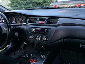
There isn't a lot to take pictures of during the process, here's the ones I tried to take while I did it: http://imgur.com/a/57XJc
End result:

The following 3 users liked this post by llDemonll:
 Mar 23, 2016, 09:28 PM
#5
EvoM Community Team Leader
this is great, congrats on reaching the finish line!

Trending Topics
Mar 24, 2016, 12:31 PM
#8
Electrical works wasn't all that bad at all. Few soldered joints when making the sub-harness on the air control motors, run a few other wires, but no custom work by any means. about as difficult as installing gauges and running power and wires for them all. obviously much more involved than that because you have to de-pin connectors, but i did the whole install in a day once i had all the stuff. sourcing everything was 50% of the work, writing up all my wiring diagrams and making sure they were right was 40%, installing it was 10%
Apr 6, 2016, 09:51 PM
#11

-I m confused on what is needed thats from a JDM or UKDM evo? the box under parts needed looks like I have to source them off a left hand drive car. so like the servos are from an outlander. I m guessing i need the A/C ECU. i can reuse the usdm blower motor. do i need the hvac unit too?
-I do have an issue with the hot/cold on the manual controls not working with the updated gears and cable and the last fix is the blend door in the box according to the TSB from mitsu. is the servo motors going be able to move that door or i need to fix that first then do the conversion?
-I do have an issue with the hot/cold on the manual controls not working with the updated gears and cable and the last fix is the blend door in the box according to the TSB from mitsu. is the servo motors going be able to move that door or i need to fix that first then do the conversion?
Apr 7, 2016, 07:43 AM
#12
-I m confused on what is needed thats from a JDM or UKDM evo? the box under parts needed looks like I have to source them off a left hand drive car. so like the servos are from an outlander. I m guessing i need the A/C ECU. i can reuse the usdm blower motor. do i need the hvac unit too?
-I do have an issue with the hot/cold on the manual controls not working with the updated gears and cable and the last fix is the blend door in the box according to the TSB from mitsu. is the servo motors going be able to move that door or i need to fix that first then do the conversion?
Apr 7, 2016, 10:10 PM
#13
so get everything in that on that parts list. use the HVAC housing. it should have provisions to screw in the servos. modify the blower motor housing to fit the galant blower moter. is all galant blower motors have the 4 pin connector? and the 92mm rod. is there a part number for that?
Apr 8, 2016, 07:39 AM
#14
correct; stock hvac housing has all the provisions for the servo motors
blower motor will need some modification, i forgot about this and have added pictures. i dont know if all galant blower motors will work, you'll need to check if the part is compatible
The rod I can't find. It's supposed to be a part of the servo motors as far as i can tell but anyone who is pulling the servo motors off of wrecked cars doesn't include it
The following users liked this post:
Huy's Evo (Apr 8, 2016)

