how to install different front seats - with no fault codes
 Jun 15, 2009, 11:25 AM
#16
Newbie
Thread Starter

 i guess i could have saved $100 by swapping out the sensors underneath my GSR recaros to my MR recaros.
 Jun 24, 2009, 12:08 PM
#18
Evolving Member
Join Date: Sep 2007
Location: Calgary, AB Canada
Posts: 211
Likes: 0
Received 0 Likes
on
0 Posts
ok im quite nub at this but for the 2 ohm resistor wht watt should i get?
is it still a 2 ohm 1/2 watt resistor? same thing as 5 1/2 watt 10 ohm resistor?
is it still a 2 ohm 1/2 watt resistor? same thing as 5 1/2 watt 10 ohm resistor?
Jun 24, 2009, 01:14 PM
#19
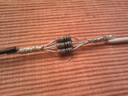
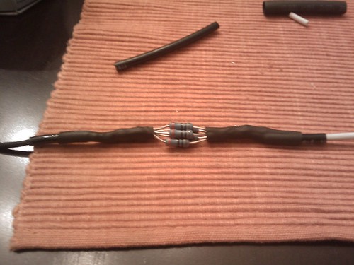
2ohm 1/2 watt resistors are a bit tough to locate. I did what the OP did. Got 5 10ohm 1/2 watt resistors and wired them together in parallel.
You can also try 2ohm 1/4 watt resistors which are easier to find and the more common factor they come in.
1:
2:
3:

You can also try 2ohm 1/4 watt resistors which are easier to find and the more common factor they come in.
1:
2:
3:
Last edited by antics22; Jun 24, 2009 at 01:32 PM.
Jul 7, 2009, 02:41 PM
#21
Newbie
Thread Starter
Don't know for sure. It depends how much tolerance the main SRS ECU has for variations in expected resistance of that airbag.
I think there's no downside to trying the 2.2 and seeing if it works.
If it doesn't work, you'll get a warning light and fault code, and you will have to get a 2 ohm resistor anyway. The warning light should go away when you get the right resistor in, but maybe the fault code will stay in memory until cleared (not sure about the last part).
Sep 1, 2009, 12:52 PM
#22
Account Disabled
iTrader: (546)
Join Date: May 2003
Location: driving the 10 second beast in ohio or running lightmods.net
Posts: 3,876
Likes: 0
Received 0 Likes
on
0 Posts
i swapped the seats and belts out....got the airbag light on the dash . will the light go off if i just do the resistors?
Sep 7, 2009, 11:46 AM
#23
Newbie
Thread Starter
Might need a step 2 - if you changed belts, ECUs may need to "see' the sensor in the OEM receiving buckles.
Might need a step 3 - do you have the passenger seat mounted on the OEM bottom bracket with the 4 weight sensors and related ECU ?
May 23, 2011, 10:23 AM
#25
while attempting to help my friend out with his BRIDE seat install this past weekend, we thought about removing the four weight sensors from the OE rails, placinging them back to back and then creating a clamp as to put pressure on the sensors at all times, then placing the whole thing underneath the passengerside seat and zip tie into place... ( since he did not want to fab up a bracket to use with the bride rails.. )
has anyone else thought of doing this?
the sensors are free floating inbetween the aluminum housing, by placing the clamp over the rounded sensor, it could fake a weight (depending on how thick the metal grey bracket is and how much you tighten the two side bolts down to...
have not yet attempted this, but we will soon..
attached is a MSpaint drawing..
May 23, 2011, 11:24 AM
#26
Evolved Member
^^^ any results with placing the sensors together and clamping them? I'm looking to swap seats out after this deployment....
May 31, 2011, 04:12 PM
#27
Newbie
iTrader: (2)

Join Date: Oct 2010
Location: Long Island
Posts: 31
Likes: 0
Received 0 Likes
on
0 Posts
while attempting to help my friend out with his BRIDE seat install this past weekend, we thought about removing the four weight sensors from the OE rails, placinging them back to back and then creating a clamp as to put pressure on the sensors at all times, then placing the whole thing underneath the passengerside seat and zip tie into place... ( since he did not want to fab up a bracket to use with the bride rails.. )
has anyone else thought of doing this?
the sensors are free floating inbetween the aluminum housing, by placing the clamp over the rounded sensor, it could fake a weight (depending on how thick the metal grey bracket is and how much you tighten the two side bolts down to...
have not yet attempted this, but we will soon..
attached is a MSpaint drawing..
has anyone else thought of doing this?
the sensors are free floating inbetween the aluminum housing, by placing the clamp over the rounded sensor, it could fake a weight (depending on how thick the metal grey bracket is and how much you tighten the two side bolts down to...
have not yet attempted this, but we will soon..
attached is a MSpaint drawing..
Jan 8, 2012, 01:02 PM
#28
Evolving Member
iTrader: (15)
Join Date: May 2006
Location: Clarksburg, West Virginia
Posts: 271
Likes: 0
Received 1 Like
on
1 Post
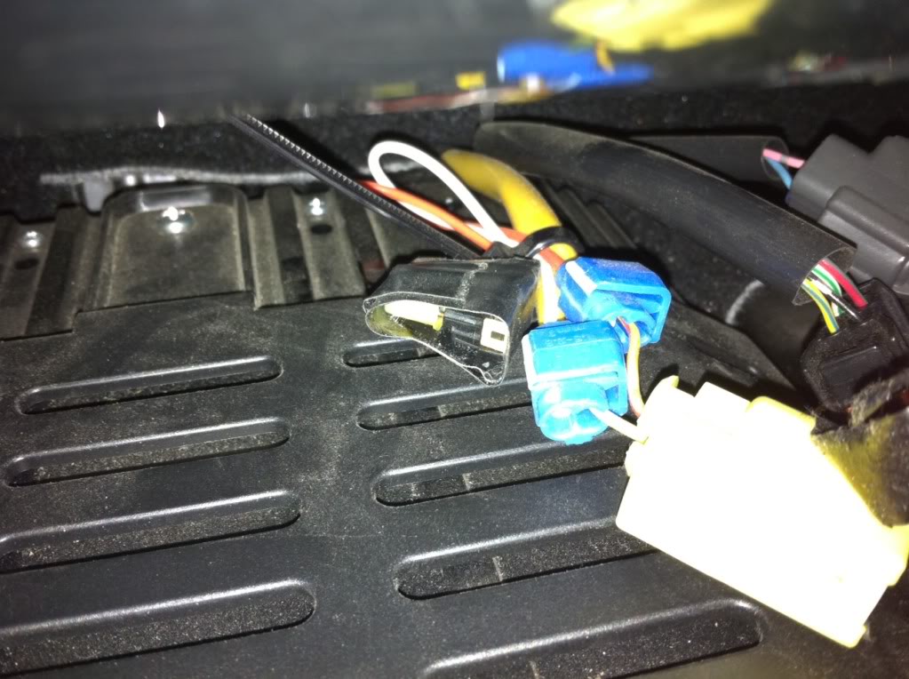
Anyone have some pictures of where the resistors need to be wired in at and what it looks like after its hooked back up? I'm an electrical dummy and need some pics haha.