When you click on links to various merchants on this site and make a purchase, this can result in this site earning a commission. Affiliate programs and affiliations include, but are not limited to, the eBay Partner Network.
HOW TO: Install ProSport EVO boost gauge on your Evo X
Evo X How Tos / InstallationsPost or link to your detailed how to / installation articles in here. If you have any questions regarding the how tos, feel free to post them in the Request sub-forum.
UPDATED! HOW TO: Install ProSport EVO boost gauge on your Evo X
So i've read the Evo X Boost Gauge Install ,No splicing, No firewall drilling,Pics+Vid= Clean As Hell and I figured I might as well add some stuff to the tutorial for people working with the ProSport EVO gauge. It is a little bit more confusing. I'm gonna take you guys through step-by-step and if there are sections that are exactly the same as the previous tutorial I will simply quote them directly from there.
So first things first, make sure you have the tools. You need
The boost gauge
T-splitter
Filter for vacuum line
Boost sender
Vacuum line
A Pair of Scissors
Pliars
Tweezers
A 10mm socket/wrench
A hook (me and my friend made one out of a piece of wood and a paper clip)
A flathead screwdriver
Also, you will need four sets of color coordinated 24 gauge wires. I bought mine from Fry's but I'm sure radioshack or home depot carry them as well.
Also I would suggest having a friend help you. You could do this by yourself but if my friend didn't help me I wouldve spend a lot more time on this install.
Difficulty: 6/10 if it's your first time, mostly due to leading the wires through the fender. 4/10 if you've done it before.
Length of time spent installing depends on experience level. Avg of 3 hours.
Now first things first, make sure to disconnect your battery's ground cable. This will prevent possible damage to the elctrical circuits.
So when you get your boost gauge, all you get with it is a T splitter for the vacuum hose, a filter for the vacuum hose leading to the boost sender, a boost sender, a hose, a gauge, a u-bracket, a bunch of bolts, and a set of wires. For this first part, all you need is the hose, the filter, the T splitter, and the boost sender.
Before you get underneath the hood, get in front of your table and prep the hose and the splitter and the filter, because those take a bit of time. I used my own T that I purchased from NAPA, because it was customize-able, thus I had no issues fitting the hoses over the splitter ends.
First, fit the vacuum hose over the bottom section of the T
Then cut the hose about 6 inches away from the bottom of the T. Here, you will install the filter for the vacuum line. You don't want any debris going into the boost sender.
Fasten with zip-ties (not necessary since these are vacuum lines, but highly recommended), and get underneath the hood.
Here's a diagram to help you out:
Originally Posted by ZWingerRyRy
Cut the vac tube about right in the middle then use the T Joint with the horizontal fittings reconnect the hose back then use the last fitting thats perpendicular facing attach to the vac tube going to the sensor, Also i prob would get some clamps or zip-tie to hold it just because, although Defis T Joints are Expanded at the tips to hold the tube pretty damn good its already pretty tight, but you just spent $35k whats a dollar or two.
End engine result and i just put the sensor in-between to keep it there til i find a good place to mount it.
Here's a pic of what it looked like for me after the install. The vacuum line was led underneath the airbox for better organization:
Moving on to the second part. This is where we get electrical. Make sure your battery ground is disconnected. Do not touch any of the fuse boxes yet. For now all we're doing is leading wires across the car to the other side. Before we begin, the Prosport Evo gauge comes with ground cables. I used the bolt on the side of the driver side console as a ground connection.
Here's a great detailed guide on how to take your interior panels off safely: Click here
Remove the A-Pillar (only if you're mounting it on the A pillar, otherwise you don't need to remove this), the driver's side dash trim, the lower piece covering the engine opening lever and the plastic piece next to the driver's side seat. Find the green wire. You're gonna move this wire across the entire front end of the car to the boost sender. Follow the instructions:
Originally Posted by ZWingerRyRy
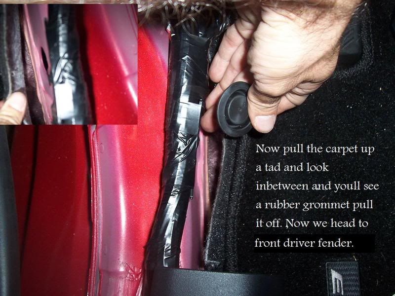
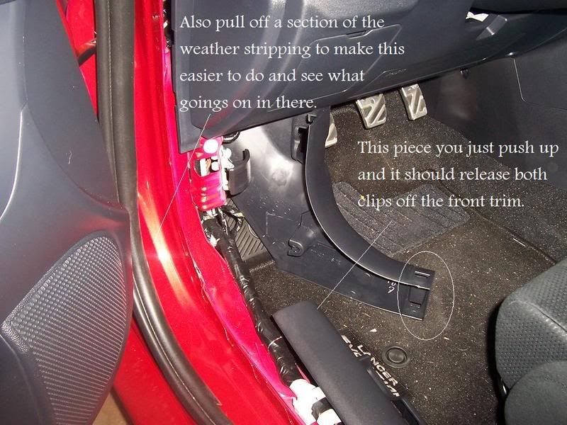
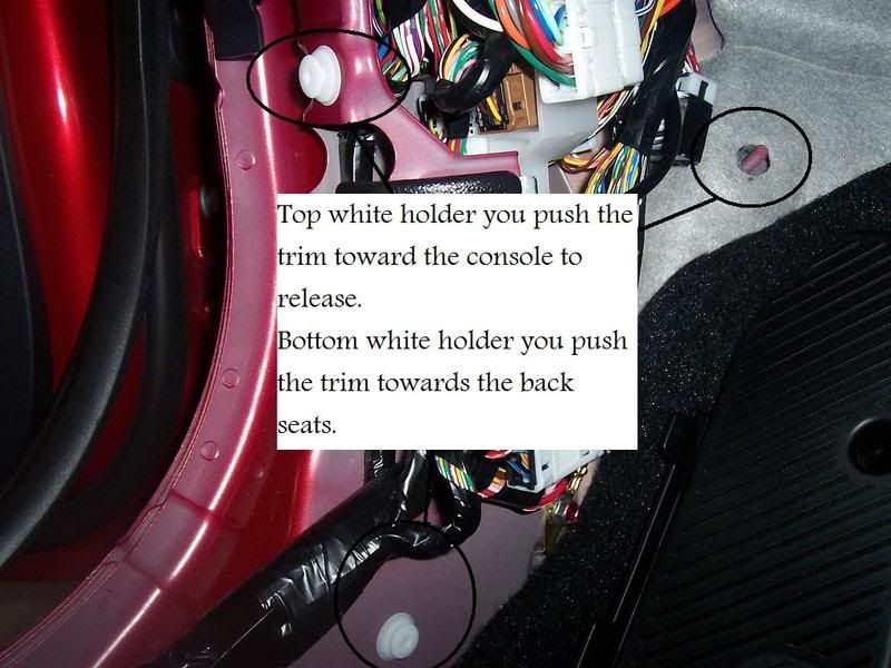
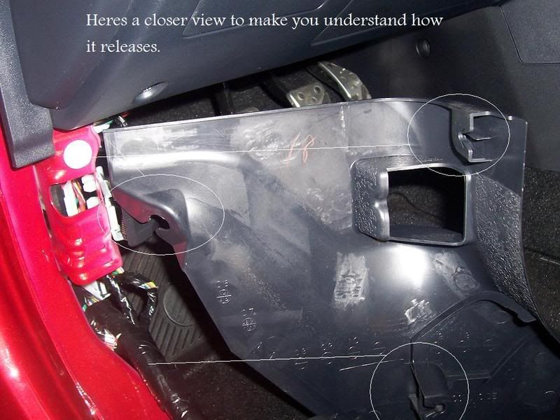
Now in the same spot start taking off the trim, but first pull a section of the weather stripping off to make this easier don't worry it'll go right back on just remember how it was when you took it off as some of the flaps on the weather stripping belongs under the trim.First start with the hood latch trip and pull it til its somewhat lose then the door sill trim just pull it up it should release. Then as the pic shows what direction and where the holders are located.
Once that is set and done. Take a closer look by the carpet just about right where the latch and sill trim connect pull up the top carpet piece and you'll find a grommet piece. Pull it off then drill or poke a decent hole don't worry as the rubber will expand and close your holeCaution with this grommet as its much weaker then the fender wall grommets, Now leave that for now and we head to the fender wall.
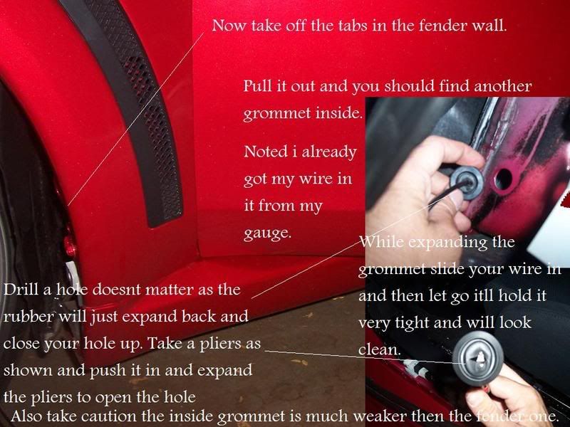
Now this isn't to hard just take off the tabs on the fender wall. a flathead usually does the trick. Pull it out a bit and take a peak in and you'll notice another black grommet. Pull that out drill a hole same thing will happen with expansion but you just take a pliers expand the hole run the wire through then let it expand back and it'll hold it nice and tight. Now run the wire through the grommet and give a good amount to reach your gauge.
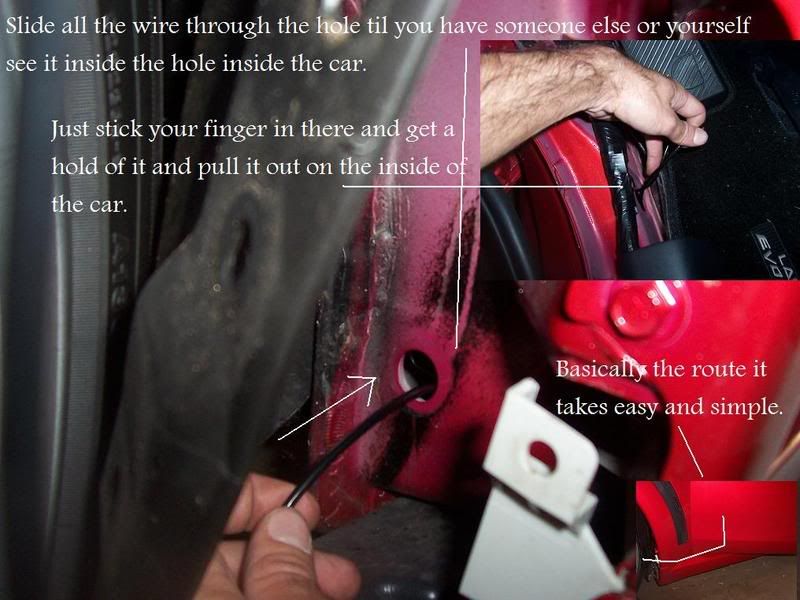
Run the wire through the hole til it reaches the other side and pull it out.
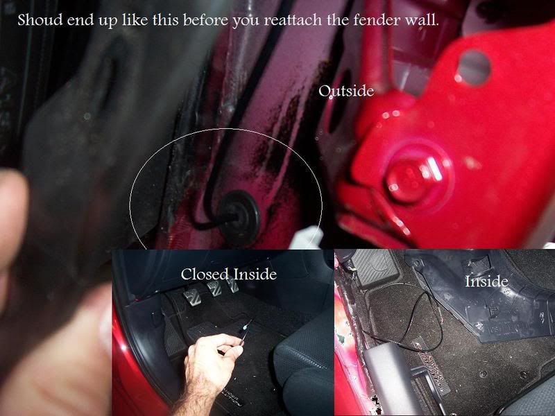
Then should end up looking like this.
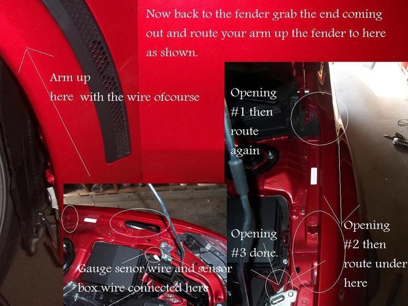
Now for the last part this is how i did it keeping the fender wall open. take the other side of the sensor wire and route it up the fender and up-to the hinge right by the hood. Then get up there and route again in the fender til you reach in-front of the fuse box. Then again just route it under that last piece and should look like this.
This is a very short guide on how to connect your wires so the gauge comes on with ignition. Make sure to connect the green wire from the boost gauge to the white wire from the boost sender. Cover with electrical tape! Instead of moving the red and orange/white wire all the way to the main fuse box, simply use the driver side fuse box. (You will still have to take the green wire across to hook it up to the white wire on the boost sender). Connect the red wire to the accessory fuse (blue 15) above the (red 10) and below the (blue 15). This will give it 12v of required power.
Now I connected the orange wire because I wanted my gauge to be red. Here's a diagram to help you decide which colors you need and also to give you a basic idea of the voltage input.
Connect the orange wire to the second accessory fuse (blue 15) under the (red 10) as shown in the picture below:
If you're also using the white wire, you will have to lead it to the headlight switch fuse which is in the engine bay fuse box. If you're using only the white wire, also simply connect it to the same fuse
All you should have left in your main fuse box is the red wire from the boost sender connected to the engine fuse (Yellow 20), as shown below:
My dad schooled me on how to conceal wires and the boost sender. He's a genius:
And that's it! Simple and plain! Enjoy your gauge!
Here're the video guides:
Video guide:
Part 1: Vacuum lines
Video of the gauge in action (connected using the second guide above)
This is being updated.
Once you've done all of that, cover the wires with electrical tape, reconnect the battery and test. To turn the boost gauge on, simply flick the high beams. Calibrate the boost gauge and you're good to go!
Thanks to ZWingerRyRy for a great write up that can be found here
Last edited by mrwickd123; Sep 14, 2013 at 11:08 AM.
I have my gauge hooked up just like this and the gauge stays on red, even with car off and not on acc to turn the gauge on. It never did this till recently. It would only turn on with the key on acc. Why is my guage still glowing.. And why do people never upload pictures like i did? Of the actual wiring.
taying on now?
Green from gauge to white from sensor<br/>Black from sensor/ black from gauge to ground<br/>Red from gauge/ red from sensor to 15a blue<br/>Orange from guage to 15a blue
 Jul 28, 2013, 09:27 PM


 Pull it off then drill or poke a decent hole don't worry as the rubber will expand and close your holeCaution with this grommet as its much weaker then the fender wall grommets,
  Now leave that for now and we head to the fender wall.