4g94 Forged internals rebuild steps by step guide
 Jan 26, 2015, 11:20 AM
#1
Evolved Member
Thread Starter
4g94 Forged internals rebuild steps by step guide
Hey guys this winter i took my blown evo 8 turbo out of my car to replace it with an evo 9 turbo. While i was there i decided it would be the perfect time to rebuild my engine block with forged internals. I taught some of you guys would like to see a complete engine build thread for the 4g94 with a step by step guide including torque specs and prep work. I AM NOT RESPONSIBLE FOR ANY PROBLEMS RELATED TO THIS ENGINE BLOCK THREAD. I sent my engine block to a machine shop today and i will get it back in a few days but here's what the block is getting:
Parts:
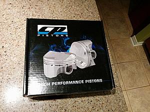
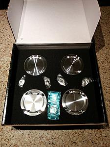
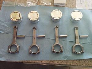
-Cp forged pistons 82mm (3.228''), 0.50mm (0.020) oversize
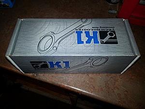
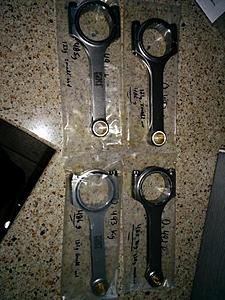
-K1 forged connecting rods
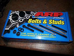
-Arp head studs (part#203-4204)
-Gates racing timing belt
-Rebuild head
-Mishimoto oil sandwich adapter w/ thermostatic switch for oil cooler
-Amsoil 10w30 Dominator synthetic racing oil
-Connecting rod bearings
-Main bearings
-Beck/Arnley water pump
-Beck/Arnley injector o-ring kit
-Oem timing belt tensioner and spring
-Oem thermostat
-Oem head gasket
-Oem front and back crank seals
-Oem dipstick tube
-Oem lower oil pan
-Oem exhaust and intake manifold gaskets
-Oem EGR gasket
-Oem throttle body gasket
-Oem oil filter
-Oem coolant pipe o-rings
Labor:
-Engine block acid bath 50$
-Engine block sonoflux 50$
-Resurface the engine block deck 95$
-Cylinder boring 0.50mm (0.020'') oversize 140$
-New frost plugs 68$
-Piston rings gapped to spec for a turbo application 125$
-Polished crank 50$
-Rod to pin fitting 30$
-Engine block internals balanced 225$
Other random parts:
-Evo 9 turbo up from an evo 8 9.8t turbo
-Mishimoto 19 rows oil cooler
-Progress 19mm rear sway bar
-Glowshift oil pressure gauge
-Custom hockey puck urethane engine mounts
-Obx silicone radiator hoses
I will keep this threat updated as i get the engine block back from the machine shop! For now here's a few pictures of the parts:
Parts:
-Cp forged pistons 82mm (3.228''), 0.50mm (0.020) oversize
-K1 forged connecting rods
-Arp head studs (part#203-4204)
-Gates racing timing belt
-Rebuild head
-Mishimoto oil sandwich adapter w/ thermostatic switch for oil cooler
-Amsoil 10w30 Dominator synthetic racing oil
-Connecting rod bearings
-Main bearings
-Beck/Arnley water pump
-Beck/Arnley injector o-ring kit
-Oem timing belt tensioner and spring
-Oem thermostat
-Oem head gasket
-Oem front and back crank seals
-Oem dipstick tube
-Oem lower oil pan
-Oem exhaust and intake manifold gaskets
-Oem EGR gasket
-Oem throttle body gasket
-Oem oil filter
-Oem coolant pipe o-rings
Labor:
-Engine block acid bath 50$
-Engine block sonoflux 50$
-Resurface the engine block deck 95$
-Cylinder boring 0.50mm (0.020'') oversize 140$
-New frost plugs 68$
-Piston rings gapped to spec for a turbo application 125$
-Polished crank 50$
-Rod to pin fitting 30$
-Engine block internals balanced 225$
Other random parts:
-Evo 9 turbo up from an evo 8 9.8t turbo
-Mishimoto 19 rows oil cooler
-Progress 19mm rear sway bar
-Glowshift oil pressure gauge
-Custom hockey puck urethane engine mounts
-Obx silicone radiator hoses
I will keep this threat updated as i get the engine block back from the machine shop! For now here's a few pictures of the parts:


Last edited by marcouxa1; Aug 28, 2016 at 07:04 AM.

The following users liked this post:
03_OZRally (Nov 21, 2020)
Jan 26, 2015, 06:15 PM
#3
Evolving Member

nice mate what headgasket ?
also i think i remember reading somewhere that the k1 rods need modifying due to they hit somewhere on the block. im not 100% on this i maybe wrong aswell
also i think i remember reading somewhere that the k1 rods need modifying due to they hit somewhere on the block. im not 100% on this i maybe wrong aswell
Jan 26, 2015, 07:10 PM
#4
Evolved Member
Thread Starter
I got my head rebuilt too a few months ago and it cost me around 450$ CAD they measures and cleaned everything and changed the valve stem seals. All of the machining including main, rods and thrust bearings will be around 1100$ CAD
Jan 26, 2015, 07:13 PM
#5
Evolved Member
Thread Starter
Its an oem head gasket look at the parts list. As for the k1 rods i heard the same but i will cover that if applicable in the thread
Jan 27, 2015, 06:18 AM
#7
Evolved Member
Thread Starter
Trending Topics
Jan 30, 2015, 05:52 PM
#8
Evolved Member
Thread Starter
AIright guys so i got my engine block from the machine shop on Wednesday around noon. I have been waiting for this moment for at least 2 months now!!! I will try to explain the build of the engine the best i can with the pictures i have because of course i was focused on building the engine and in some cases i didn't take a picture of the progress. It is important that you print the correct pages of the 4g9 service manual before you start the assembly of your engine. Link to the 4g9 service manual is here:http://www.mivec.co.nz/tech/4G9x_Engine_Manual.pdf
So lets start this build right here:
Engine block and internals machining:
-When you get to the machine shop you want to tell them to fit your piston pins into your connecting rods if they don't fit already. Aftermarket pistons and rods use a floating piston pin compared to the OEM press fit piston pins. Your piston rings cap will have to be checked and/or filed to the correct spec depending on if you have a N/A (naturally aspirated (OEM)) or turbocharged engine. Make sure you tell your machine shop to follow your piston manufacturer's piston ring end gap chart and use the correct specs for your current application. As for the Cp pistons the ring end gap formula being turbocharged for the first compression ring is the following: BORE x .0055''. In my case i have the 82mm (3.228'') pistons so my first compression rings are gapped to 0.017''. The formula for the second compression ring is the following: 0.017''+ 0.004'' to 0.008' so in between 0.021'' to 0.025'' is good. The oil rings should not be filed and should be at a minimum of 0.015''.
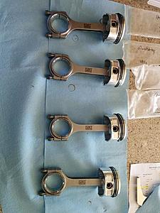
Piston and connecting rod assembly:
Now that your piston pins and piston ring end gaps were fitted and/or checked you can install your piston/rod assembly. When installing piston rings onto the piston you want to start with the 3 oil rings then install your 2nd compression ring and then your 1st compression ring using your manufacturer's technique in the service manual. Next you can install your piston pin lock wire on 1 side of the piston with the piston pin in place to stop the lock wire to go past its groove. Remove the piston pin from the piston and put assembly lube on the connecting rod small end and on the piston pin. Install your connecting rod inside your piston and lock it in place with the piston pin. Your connecting rod should now move smoothly with the piston pin inside of it. Install your 2nd lock wire on the other side of the piston pin to lock the connecting rod in place. Your piston assembly is now ready to install in your engine block.
#4 connecting rod fitting (K1 rods only):
Now before you install your crankshaft permanently in your engine block you want to clean and install the crankshaft and main/thrust bearings in place with assembly lube without the girdle tightened. Lubricate the cylinder wall, piston rings and skirts using engine oil then install the #4 piston and rod assembly inside your #4 cylinder. With the k1 rods the big end cap will hit on an oil gallery on the left side when looking from the timing belt side of the engine block. Use a white paint marker and draw a line from top to bottom on the rod and rod cap. Apply assembly lube on both the rod and rod cap bearings. Tighten the rod bolts by hand only and turn the crankshaft by hand clockwise. Now you should see a paint mark on the engine block's oil gallery like this: (paint mark is on the right side in the picture)
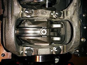
From here you have a starting point on where to grind off the excess metal on the oil gallery. Using a dremel/grinder with a carbide bit slowly grind the oil gallery to take the excess metal off. CAUTION: DO NOT GRIND TOO MUCH OFF OR YOU WILL PEIRCE YOUR OIL GALLERY AND DESTROY YOUR ENGINE BLOCK. This step is now trial and error pretty much so grind a little bit, put your crankshaft back with the rod attached, turn the crankshaft and see if it's still in the way or not untill there is at least 0.025'' clearance.
Crankshaft and girdle installation:
Once you have your #4 rod clearing the oil gallery you can take your piston off of it's cylinder and remove the crankshaft. Use an aspirator to remove the majority of the metal shavings left from grinding. From here you have to clean every main bearing,cylinder wall, oil gallery and crankshaft journals with brake/carb cleaner and a lint free cloth to be ready for the install. If you have aftermarket bearings in a different size other than std or if you want to make sure your oil clearances are good with your new bearings you can use plastigauge to verify. Install your crankshaft without any lubrication on both the main bearings and the crankshaft. Put a piece as big as the width of the bearings on the crankshaft journals and Install the main bolts only hand tight on the girdle. Once the main bolts are hand tight in place you can use a rubber mallet and hit the girdle slowly on both side to make the girdle flush with the block. Once that is done you can hand tight the main bolts again and follow the torque sequence. Do not turn your crankshaft or your plastigauge will spread everywhere on your crank journals and will not give you accurate readings. Now remove your girdle in 3 different loosening steps. I usually loosen the main bolts in a sequence of 3x 45* in the reverse tightening sequence. If you're having a hard time getting the girdle off after removing the main bolts you can use a small prybar with a lint free cloth at the end of it and slowly pry in between the engine block and the girdle 1 side at the time. When the girdle is off you can see a green/red/blue line on your crank journals depending on what make/color plastigauge you're using. Use the plastigauge paper to compare the width of the line on your crank journals with the chart on the paper. The spec for the main bearing oil clearance is in between 0.02-0.04mm and the limit for the bearings is 0.1mm.
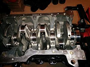
If everything is in spec you can clean the crankshaft journals where the plastigauge was and get ready for the final install. Now that everything is clean and foreign material free you can lubricate your crank journals, thrust and main bearings on both the block and girdle with assembly lube. Carefully install the crankshaft in place with the keyed end towards the timing belt side of the block. Put the girdle with the arrow on top facing towards the timing belt side also. Install the main bolts only hand tight on the girdle with engine oil on the threads. Once the main bolts are hand tight in place you can use a rubber mallet and hit the girdle slowly on both side to make the girdle flush with the block. Once that is done you can hand tight the main bolts again and follow the torque sequence for your final crankshaft assembly. The torque sequence for the main cap bolts is the following:
1.Tighten the bearing cap bolts to 25 Nm torque in the tightening sequence.
2.Make a paint mark on the head of each bolt.
3.make a paint mark on the area around the bolt bearing surface at location 90* to 100* in the direction of tightening the bolt, as referenced from the paint mark on the bolt head.
4.Give a 90* to 100* turn to the bolts in the tightening sequence. Make sure that the paint mark on the bolt and that on the arena around the bolt bearing surface are in alignment.
After installing the bearing caps, make sure that the crankshaft turns smoothly. From here you want to check for your crankshaft end play with a dial gauge indicator. If you don't have access to a dial gauge indicator you can use a feeler gauge but the reading is less accurate. The std value for the crankshaft end play is in between 0.05-0.25mm with a service limit of 0.4mm.
So lets start this build right here:
Engine block and internals machining:
-When you get to the machine shop you want to tell them to fit your piston pins into your connecting rods if they don't fit already. Aftermarket pistons and rods use a floating piston pin compared to the OEM press fit piston pins. Your piston rings cap will have to be checked and/or filed to the correct spec depending on if you have a N/A (naturally aspirated (OEM)) or turbocharged engine. Make sure you tell your machine shop to follow your piston manufacturer's piston ring end gap chart and use the correct specs for your current application. As for the Cp pistons the ring end gap formula being turbocharged for the first compression ring is the following: BORE x .0055''. In my case i have the 82mm (3.228'') pistons so my first compression rings are gapped to 0.017''. The formula for the second compression ring is the following: 0.017''+ 0.004'' to 0.008' so in between 0.021'' to 0.025'' is good. The oil rings should not be filed and should be at a minimum of 0.015''.
Piston and connecting rod assembly:
Now that your piston pins and piston ring end gaps were fitted and/or checked you can install your piston/rod assembly. When installing piston rings onto the piston you want to start with the 3 oil rings then install your 2nd compression ring and then your 1st compression ring using your manufacturer's technique in the service manual. Next you can install your piston pin lock wire on 1 side of the piston with the piston pin in place to stop the lock wire to go past its groove. Remove the piston pin from the piston and put assembly lube on the connecting rod small end and on the piston pin. Install your connecting rod inside your piston and lock it in place with the piston pin. Your connecting rod should now move smoothly with the piston pin inside of it. Install your 2nd lock wire on the other side of the piston pin to lock the connecting rod in place. Your piston assembly is now ready to install in your engine block.


#4 connecting rod fitting (K1 rods only):
Now before you install your crankshaft permanently in your engine block you want to clean and install the crankshaft and main/thrust bearings in place with assembly lube without the girdle tightened. Lubricate the cylinder wall, piston rings and skirts using engine oil then install the #4 piston and rod assembly inside your #4 cylinder. With the k1 rods the big end cap will hit on an oil gallery on the left side when looking from the timing belt side of the engine block. Use a white paint marker and draw a line from top to bottom on the rod and rod cap. Apply assembly lube on both the rod and rod cap bearings. Tighten the rod bolts by hand only and turn the crankshaft by hand clockwise. Now you should see a paint mark on the engine block's oil gallery like this: (paint mark is on the right side in the picture)

From here you have a starting point on where to grind off the excess metal on the oil gallery. Using a dremel/grinder with a carbide bit slowly grind the oil gallery to take the excess metal off. CAUTION: DO NOT GRIND TOO MUCH OFF OR YOU WILL PEIRCE YOUR OIL GALLERY AND DESTROY YOUR ENGINE BLOCK. This step is now trial and error pretty much so grind a little bit, put your crankshaft back with the rod attached, turn the crankshaft and see if it's still in the way or not untill there is at least 0.025'' clearance.
Crankshaft and girdle installation:
Once you have your #4 rod clearing the oil gallery you can take your piston off of it's cylinder and remove the crankshaft. Use an aspirator to remove the majority of the metal shavings left from grinding. From here you have to clean every main bearing,cylinder wall, oil gallery and crankshaft journals with brake/carb cleaner and a lint free cloth to be ready for the install. If you have aftermarket bearings in a different size other than std or if you want to make sure your oil clearances are good with your new bearings you can use plastigauge to verify. Install your crankshaft without any lubrication on both the main bearings and the crankshaft. Put a piece as big as the width of the bearings on the crankshaft journals and Install the main bolts only hand tight on the girdle. Once the main bolts are hand tight in place you can use a rubber mallet and hit the girdle slowly on both side to make the girdle flush with the block. Once that is done you can hand tight the main bolts again and follow the torque sequence. Do not turn your crankshaft or your plastigauge will spread everywhere on your crank journals and will not give you accurate readings. Now remove your girdle in 3 different loosening steps. I usually loosen the main bolts in a sequence of 3x 45* in the reverse tightening sequence. If you're having a hard time getting the girdle off after removing the main bolts you can use a small prybar with a lint free cloth at the end of it and slowly pry in between the engine block and the girdle 1 side at the time. When the girdle is off you can see a green/red/blue line on your crank journals depending on what make/color plastigauge you're using. Use the plastigauge paper to compare the width of the line on your crank journals with the chart on the paper. The spec for the main bearing oil clearance is in between 0.02-0.04mm and the limit for the bearings is 0.1mm.

If everything is in spec you can clean the crankshaft journals where the plastigauge was and get ready for the final install. Now that everything is clean and foreign material free you can lubricate your crank journals, thrust and main bearings on both the block and girdle with assembly lube. Carefully install the crankshaft in place with the keyed end towards the timing belt side of the block. Put the girdle with the arrow on top facing towards the timing belt side also. Install the main bolts only hand tight on the girdle with engine oil on the threads. Once the main bolts are hand tight in place you can use a rubber mallet and hit the girdle slowly on both side to make the girdle flush with the block. Once that is done you can hand tight the main bolts again and follow the torque sequence for your final crankshaft assembly. The torque sequence for the main cap bolts is the following:
1.Tighten the bearing cap bolts to 25 Nm torque in the tightening sequence.
2.Make a paint mark on the head of each bolt.
3.make a paint mark on the area around the bolt bearing surface at location 90* to 100* in the direction of tightening the bolt, as referenced from the paint mark on the bolt head.
4.Give a 90* to 100* turn to the bolts in the tightening sequence. Make sure that the paint mark on the bolt and that on the arena around the bolt bearing surface are in alignment.
After installing the bearing caps, make sure that the crankshaft turns smoothly. From here you want to check for your crankshaft end play with a dial gauge indicator. If you don't have access to a dial gauge indicator you can use a feeler gauge but the reading is less accurate. The std value for the crankshaft end play is in between 0.05-0.25mm with a service limit of 0.4mm.

Last edited by marcouxa1; Jan 31, 2015 at 09:43 AM.
The following users liked this post:
03_OZRally (Nov 21, 2020)
Jan 30, 2015, 06:03 PM
#9

Do you have the model number on CrankShaft bearings and rod bearings? How much clearence do you have on the main bearings and thrust bearing?
Also do you forsee any clearence issues with the oem headgasket or does the overbore on the cylinder wall still allow enough surface area for the headgasket to seal?
Good luck with the build it looks awesome so far.
Also do you forsee any clearence issues with the oem headgasket or does the overbore on the cylinder wall still allow enough surface area for the headgasket to seal?
Good luck with the build it looks awesome so far.
Jan 31, 2015, 08:43 AM
#10
Evolved Member
Thread Starter
Piston installation:
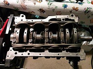
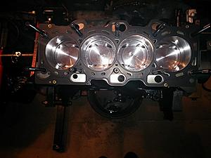
Now that your crankshaft is installed for good it's time to get your piston assembly in that bad boy! Before you do anything make sure you clean and lubricate the piston rings , skirts and cylinder walls with engine oil. Once that is done you must use a piston ring compressor to allow your pistons to fit inside your cylinders without breaking rings. You can usually find a ring compressor at any parts store. Make sure you tighten the compressor as much as you can with the compressor's grooved side facing the engine deck to allow it to be completely flat with the engine. Make sure your pistons are facing the right way with the connecting rod big end parallel with the connecting rod journal on the crankshaft and have the rod journal at BDC (bottom dead center). Hit the ring compressor with a rubber mallet all around the edge to make sure the tool is flat evenly on the deck. From here you can either use your hands to push the pistons through the cylinders or gently hit it with a plastic/wooden hammer handle. If the piston doesn't go in easily stop and make sure your piston rings are not binding on the engine deck because if you force the piston in with the ring binding on the deck you might break the rings and that is never a good thing especially when your pistons are a special order! Repeat this step for all 4 pistons and make sure your rod journals and bearings are lubricated with assembly lube prior to assembly. Make sure you install your rod caps with the rod bolts hand tight on every rod before you install another piston. When all of your pistons are in place you can now tighten your rod bolts to the connecting rod manufacturer's torque. In my case the k1 rods use ARP 3/8 bolts which requires 25 ft/lbs +55* to ensure proper bolt stretch and strength. Now before you move to the next step you want to turn your crankshaft clockwise by hand to verify that your engine turns smoothly and that there is no binding issue. Here what your pistons should look like when installed:
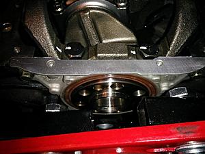
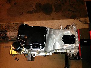
Oil pump, rear crank seal and oil pan install:
Before you install your head you want to install your oil pump, rear crank seal and oil pan especially if you're using an engine stand like i do or else you won't be able to turn your engine around anymore because it's going to be really heavy. Clean any contact area between the oil pump and engine block to remove any FM. Apply +-3mm diameter of gray gasket maker to the oil pump case on the specified location in the service manual and don't forget to install your strainer with it's gasket. Before you install your oil pan you want to get your rear crank seal in place. Again you want to clean any FM off of the engine block and seal case and apply grey gasket maker to the specified location in the service manual. If you're using an engine stand like i do you might have to get your engine block off of it because you won't have enough space to fit your rear crank seal cast in place. Now that both your rear crank and oil pump cases are in place you can install you oil pan. Again you want to clean any FM off of the contact area in between the pan and the engine block and remove any remaining gasket from the mating surfaces using a scraper or plastic brush. Apply a 4mm diameter bead of grey gasket maker to the oil pan flange in the correct location mentioned in the service manual. Make sure you install the oil pan within 15 minutes after applying the sealant.
Here's what everything should look like once installed:
Head studs install:
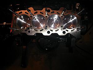
It's now time to install your head studs by hand if you have them. Make sure your engine block head stud threads are clean from any debris and that your head studs can bolt in by hand. I personally used arp's moly lube on the lower threads of the studs but i don't think you have to. Clean the engine deck to remove and FM (foreign material) Next you can install your head gasket but make sure it's in the right way because the head gasket fits in both ways. To make sure it's in the right way look at every oil and water passages to see if they're blocked by the gasket or not.
Here's what the head gasket should look like on the head with the studs installed:
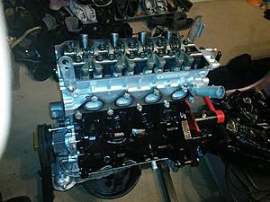
Engine head install:
Next you want to clean your engine head's head gasket area to remove any FM and gently slide your head through your head studs. I personnaly loosened the rocker arm shafts to reduce the chances of binding the opened valves when installing the timing belt. Your engine head should be evenly straight with your engine block. If you're using ARP head studs like i am you want to lubricate both the nut, washer and head stud threads with ARP's moly lube provided in the head stud kit. Put 1 washer on every stud poking inside the head and then put 1 nut hand tight over the washer. CAUTION: USE THE MANUFACTURER'S TORQUE SEQUENCE FOR HEAD STUDS!!! For our engine the torque sequence for the head bolts is the following:
1. According to the tightening sequence, tighten the bolts to the specific torque of 74 Nm.
2.Loosen all bolts fully in the reverse tightening sequence.
3.Retighten the loosened bolts to a torque of 20 Nm in the specific tightening sequence. Wait 10 minutes and recheck that every bolt is still at 20 Nm.
4.Make a paint mark on the cylinder head bolt heads and cylinder head at a 180* angle from each other.
5.Give a 90* turn to the cylinder head bolts in the specified tightening sequence.
6.Give another 90* turn to the cylinder head bolts and make sure that the paint mark on the head of each cylinder bolts and that on the cylinder head are on the same straight line.From here you have finished installed your cylinder head on your engine block.
here's what it should look like:
Now that your crankshaft is installed for good it's time to get your piston assembly in that bad boy! Before you do anything make sure you clean and lubricate the piston rings , skirts and cylinder walls with engine oil. Once that is done you must use a piston ring compressor to allow your pistons to fit inside your cylinders without breaking rings. You can usually find a ring compressor at any parts store. Make sure you tighten the compressor as much as you can with the compressor's grooved side facing the engine deck to allow it to be completely flat with the engine. Make sure your pistons are facing the right way with the connecting rod big end parallel with the connecting rod journal on the crankshaft and have the rod journal at BDC (bottom dead center). Hit the ring compressor with a rubber mallet all around the edge to make sure the tool is flat evenly on the deck. From here you can either use your hands to push the pistons through the cylinders or gently hit it with a plastic/wooden hammer handle. If the piston doesn't go in easily stop and make sure your piston rings are not binding on the engine deck because if you force the piston in with the ring binding on the deck you might break the rings and that is never a good thing especially when your pistons are a special order! Repeat this step for all 4 pistons and make sure your rod journals and bearings are lubricated with assembly lube prior to assembly. Make sure you install your rod caps with the rod bolts hand tight on every rod before you install another piston. When all of your pistons are in place you can now tighten your rod bolts to the connecting rod manufacturer's torque. In my case the k1 rods use ARP 3/8 bolts which requires 25 ft/lbs +55* to ensure proper bolt stretch and strength. Now before you move to the next step you want to turn your crankshaft clockwise by hand to verify that your engine turns smoothly and that there is no binding issue. Here what your pistons should look like when installed:

Oil pump, rear crank seal and oil pan install:
Before you install your head you want to install your oil pump, rear crank seal and oil pan especially if you're using an engine stand like i do or else you won't be able to turn your engine around anymore because it's going to be really heavy. Clean any contact area between the oil pump and engine block to remove any FM. Apply +-3mm diameter of gray gasket maker to the oil pump case on the specified location in the service manual and don't forget to install your strainer with it's gasket. Before you install your oil pan you want to get your rear crank seal in place. Again you want to clean any FM off of the engine block and seal case and apply grey gasket maker to the specified location in the service manual. If you're using an engine stand like i do you might have to get your engine block off of it because you won't have enough space to fit your rear crank seal cast in place. Now that both your rear crank and oil pump cases are in place you can install you oil pan. Again you want to clean any FM off of the contact area in between the pan and the engine block and remove any remaining gasket from the mating surfaces using a scraper or plastic brush. Apply a 4mm diameter bead of grey gasket maker to the oil pan flange in the correct location mentioned in the service manual. Make sure you install the oil pan within 15 minutes after applying the sealant.
Here's what everything should look like once installed:


Head studs install:
It's now time to install your head studs by hand if you have them. Make sure your engine block head stud threads are clean from any debris and that your head studs can bolt in by hand. I personally used arp's moly lube on the lower threads of the studs but i don't think you have to. Clean the engine deck to remove and FM (foreign material) Next you can install your head gasket but make sure it's in the right way because the head gasket fits in both ways. To make sure it's in the right way look at every oil and water passages to see if they're blocked by the gasket or not.
Here's what the head gasket should look like on the head with the studs installed:

Engine head install:
Next you want to clean your engine head's head gasket area to remove any FM and gently slide your head through your head studs. I personnaly loosened the rocker arm shafts to reduce the chances of binding the opened valves when installing the timing belt. Your engine head should be evenly straight with your engine block. If you're using ARP head studs like i am you want to lubricate both the nut, washer and head stud threads with ARP's moly lube provided in the head stud kit. Put 1 washer on every stud poking inside the head and then put 1 nut hand tight over the washer. CAUTION: USE THE MANUFACTURER'S TORQUE SEQUENCE FOR HEAD STUDS!!! For our engine the torque sequence for the head bolts is the following:
1. According to the tightening sequence, tighten the bolts to the specific torque of 74 Nm.
2.Loosen all bolts fully in the reverse tightening sequence.
3.Retighten the loosened bolts to a torque of 20 Nm in the specific tightening sequence. Wait 10 minutes and recheck that every bolt is still at 20 Nm.
4.Make a paint mark on the cylinder head bolt heads and cylinder head at a 180* angle from each other.
5.Give a 90* turn to the cylinder head bolts in the specified tightening sequence.
6.Give another 90* turn to the cylinder head bolts and make sure that the paint mark on the head of each cylinder bolts and that on the cylinder head are on the same straight line.From here you have finished installed your cylinder head on your engine block.
here's what it should look like:

Last edited by marcouxa1; Jan 31, 2015 at 10:10 AM.
The following users liked this post:
03_OZRally (Nov 21, 2020)
 Jan 31, 2015, 10:06 AM
#12
Evolved Member
Thread Starter
Timing belt install:
Next step is to install your timing belt. Since my rocker shaft is not tightened none of the valves are opened on the engine head so you can turn the crankshaft and camshaft as much as you want and nothing will cause your valves to bend or damage your piston heads. First off install your water pump using the provided paper gasket or using gray gasket maker. Install your timing belt tensionner with the spring completely compressed with the tensionner bolt tightened just enough for it not to move. Now you want to install and align your crankshaft sprocket arrow with the oil pump case arrow like this:
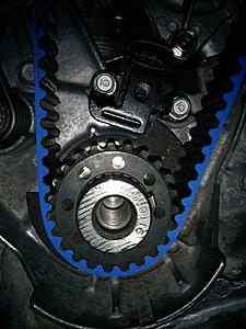
Now that your crank pulley is at TDC (top dead center) meaning that your piston #1 and #4 are completely up inside the cylinder you want to install and align your cam pulley notch with the engine head arrow. I like to paint the cam pulley notch and teeth with a white paint marker to help align it.
It should look like this:
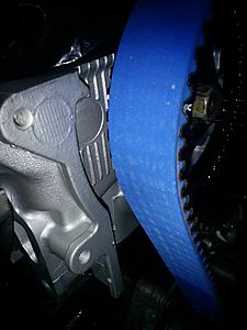
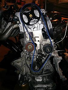
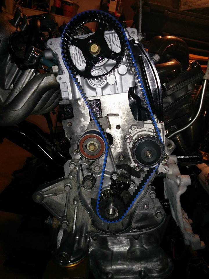
From now on your cam and crank pulleys are aligned and ready for the timing belt. Start by installing the t-belt on the crank pulley, take all of the excess loose in the t-belt and get in in the water pump grooves. Next keep tension on the t-belt but make sure the crank pulley doesn't move and slide the t-belt on your cam pulley. Sliding the t-belt on the cam pulley requires patience because it's usually a pretty tight fit as you have to keep tension from the crank pulley, to the water pump and to your cam pulley. Once your t-belt sits on your cam pulley verify that the notch on the cam pulley and crank pulley are still in line with their respective marks on the engine head and the oil pump case. When you have this double checked the timing belt should be loose on the tensionner side in between the crank and cam pulley. Loosen the tensionner bolt and the spring should put tension on the t-belt. Tighten the tensionner bolt to the correct torque and turn your crankshaft at least 3-4 full rotation. Reverify your timing marks and if everything is still aligned you are done with your timing belt. Now that everything is timed correctly you can tighten your rocker arm shaft to the specified torque in the service manual.
Here's what your t-belt should look like after the install:
T-belt covers and engine mount bracket install:
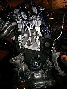
Now that your t-belt is installed you can start by installing your engine mount bracket. You want to install this first because your t-belt covers have a rubber lip that seals on the bracket and you will not ba able to install the bracket with the covers on already. Now that your bracket is in place and torques to spec you can install the metal dust protector over the water pump and then both t-belt covers. Your lower t-belt cover should have a connector molded into the case itself for the crank sensor so make sure this is aligned and connected when installing it.
Here's what you should see after those are installed without the upper case on:
From now on it's pretty straight forward for the rest of the install. All that is left is the exhaust and intake manifolds, rocker cover and coolant pipes. For more information on how to install those and what the torque specs are you can look in the 4g9 service manual link in the first page of the thread. If there is something unclear let me know and i will add them to the thread. I will post a few more pictures of the final product on the post below.
Next step is to install your timing belt. Since my rocker shaft is not tightened none of the valves are opened on the engine head so you can turn the crankshaft and camshaft as much as you want and nothing will cause your valves to bend or damage your piston heads. First off install your water pump using the provided paper gasket or using gray gasket maker. Install your timing belt tensionner with the spring completely compressed with the tensionner bolt tightened just enough for it not to move. Now you want to install and align your crankshaft sprocket arrow with the oil pump case arrow like this:
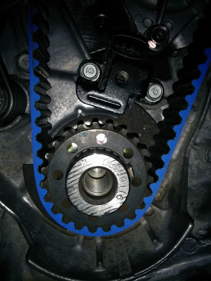
Now that your crank pulley is at TDC (top dead center) meaning that your piston #1 and #4 are completely up inside the cylinder you want to install and align your cam pulley notch with the engine head arrow. I like to paint the cam pulley notch and teeth with a white paint marker to help align it.
It should look like this:

From now on your cam and crank pulleys are aligned and ready for the timing belt. Start by installing the t-belt on the crank pulley, take all of the excess loose in the t-belt and get in in the water pump grooves. Next keep tension on the t-belt but make sure the crank pulley doesn't move and slide the t-belt on your cam pulley. Sliding the t-belt on the cam pulley requires patience because it's usually a pretty tight fit as you have to keep tension from the crank pulley, to the water pump and to your cam pulley. Once your t-belt sits on your cam pulley verify that the notch on the cam pulley and crank pulley are still in line with their respective marks on the engine head and the oil pump case. When you have this double checked the timing belt should be loose on the tensionner side in between the crank and cam pulley. Loosen the tensionner bolt and the spring should put tension on the t-belt. Tighten the tensionner bolt to the correct torque and turn your crankshaft at least 3-4 full rotation. Reverify your timing marks and if everything is still aligned you are done with your timing belt. Now that everything is timed correctly you can tighten your rocker arm shaft to the specified torque in the service manual.
Here's what your t-belt should look like after the install:
T-belt covers and engine mount bracket install:
Now that your t-belt is installed you can start by installing your engine mount bracket. You want to install this first because your t-belt covers have a rubber lip that seals on the bracket and you will not ba able to install the bracket with the covers on already. Now that your bracket is in place and torques to spec you can install the metal dust protector over the water pump and then both t-belt covers. Your lower t-belt cover should have a connector molded into the case itself for the crank sensor so make sure this is aligned and connected when installing it.
Here's what you should see after those are installed without the upper case on:

From now on it's pretty straight forward for the rest of the install. All that is left is the exhaust and intake manifolds, rocker cover and coolant pipes. For more information on how to install those and what the torque specs are you can look in the 4g9 service manual link in the first page of the thread. If there is something unclear let me know and i will add them to the thread. I will post a few more pictures of the final product on the post below.
Last edited by marcouxa1; Jan 31, 2015 at 10:39 AM.
The following users liked this post:
03_OZRally (Nov 21, 2020)


The following users liked this post:
03_OZRally (Nov 21, 2020)
Jan 31, 2015, 01:33 PM
#14
Evolved Member
Thread Starter
Do you have the model number on CrankShaft bearings and rod bearings? How much clearence do you have on the main bearings and thrust bearing?
Also do you forsee any clearence issues with the oem headgasket or does the overbore on the cylinder wall still allow enough surface area for the headgasket to seal?
Good luck with the build it looks awesome so far.
Also do you forsee any clearence issues with the oem headgasket or does the overbore on the cylinder wall still allow enough surface area for the headgasket to seal?
Good luck with the build it looks awesome so far.
Last edited by marcouxa1; Jan 31, 2015 at 01:37 PM.
The following users liked this post:
03_OZRally (Nov 21, 2020)