My Aquamist HFS-5 Install Guide
 Oct 25, 2007, 03:29 PM
#16
Evolved Member
Thread Starter
iTrader: (17)
Join Date: Nov 2005
Location: NNJ
Posts: 2,544
Likes: 0
Received 0 Likes
on
0 Posts
In my install doc I mention that you can install the jets in the inlet or outlet of the IC. I think this is enough documentation for this location. The install process for installing the jets where you installed them is the same process as where I showed.
Drill, tap, install adapter, install jet.
I don't think it would make it any easier for the users to show more than one location.
By the way, looks like you did a nice job on that install. Got any more pics?
Drill, tap, install adapter, install jet.
I don't think it would make it any easier for the users to show more than one location.
By the way, looks like you did a nice job on that install. Got any more pics?

 Nov 14, 2007, 11:09 AM
#26
Evolving Member

Join Date: Oct 2007
Location: Canada
Posts: 107
Likes: 0
Received 0 Likes
on
0 Posts
Nov 18, 2007, 07:33 PM
#28
Account Disabled
iTrader: (38)

Join Date: Aug 2005
Location: Virginia Beach, Virginia
Posts: 9,319
Likes: 0
Received 1 Like
on
1 Post
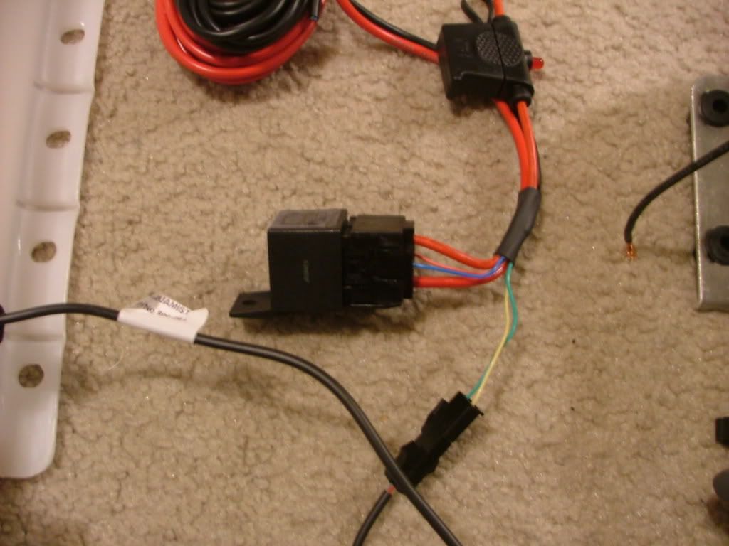
helpful guide but I'm confused, I looked at the layout in the pdf and in the guide that comes with the kit... both show a thin blue and red wire coming out of the relay and a green and yellow wire coming out of the float swtich, those 4 wires meet up in some shrink tube that's wrapped around them and the power and ground wire. The problem is that the drawings show the thin red, blue, green and yellow wires coming out of the shrink tube to the DDS3 box to connect to the p. relay + and - and the float switch and ground.
my wires go into the shrink tube but don't come out...what's the deal? I only have 3 wires coming out of my shrink tube, the battery power and ground and the fused power wire that goes to the pump.
help!
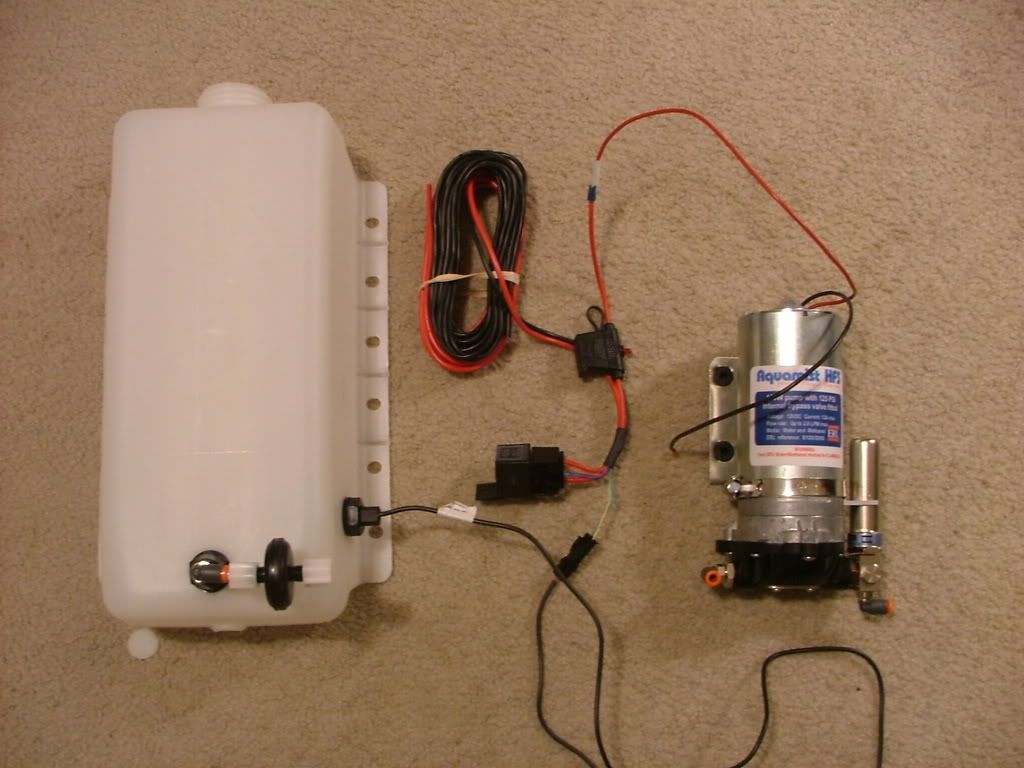
p.s. I'm not sure if I did the tank fittings for the float and supply plugs right, the guide needs to mention exactly how to do it. There's a couple of pics that come with each baggie but I'm not sure what I'm supposed to do. I did something but I suspect it's wrong because I was guessing.
frankly I'm disappointed in this kit, so many pieces should have been assembled from the factory because it leaves way too many ways to screw it up to an amateur.
I highly suggest selling tanks with the float/supply already installed, the pump fully assembled, fuse in the fuse holder, relay in the socket etc... I mean cmon, for 1k it should come with fantastic documentation with pictures (NOT DRAWINGS) and everything that can be, pre-assembled. The lack of assembly and documentation is probably fine for someone that is familiar with your kits but it's a real deal breaker for me. I have some local friends that are looking to me for help installing theirs once I'm done with mine and I'm going to tell them not only no, but hell no.
- A very frustrated Mellon
my wires go into the shrink tube but don't come out...what's the deal? I only have 3 wires coming out of my shrink tube, the battery power and ground and the fused power wire that goes to the pump.
help!
p.s. I'm not sure if I did the tank fittings for the float and supply plugs right, the guide needs to mention exactly how to do it. There's a couple of pics that come with each baggie but I'm not sure what I'm supposed to do. I did something but I suspect it's wrong because I was guessing.
frankly I'm disappointed in this kit, so many pieces should have been assembled from the factory because it leaves way too many ways to screw it up to an amateur.
I highly suggest selling tanks with the float/supply already installed, the pump fully assembled, fuse in the fuse holder, relay in the socket etc... I mean cmon, for 1k it should come with fantastic documentation with pictures (NOT DRAWINGS) and everything that can be, pre-assembled. The lack of assembly and documentation is probably fine for someone that is familiar with your kits but it's a real deal breaker for me. I have some local friends that are looking to me for help installing theirs once I'm done with mine and I'm going to tell them not only no, but hell no.
- A very frustrated Mellon
Last edited by Mellon Racing; Nov 18, 2007 at 07:40 PM.
 Nov 18, 2007, 08:05 PM
#30
Account Disabled
iTrader: (38)
Join Date: Aug 2005
Location: Virginia Beach, Virginia
Posts: 9,319
Likes: 0
Received 1 Like
on
1 Post
the end of the coiled up (pictured) wire is cut flat and I just happened to walk up to it from another angle and see the yellow/green/blue/red wires bundled up in there, pfft and here I thought that was a big thick ground wire. I guess if I would have cut open the shrink tube it would have been obvious that the skinny wires were going into that black tube and saved myself tons of time staring at drawings.

