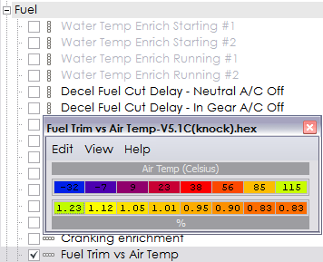
Air Temp Compensation table
 Dec 2, 2008, 11:44 AM
#31
Evolving Member

Join Date: Jun 2005
Location: McKinney TX
Posts: 259
Likes: 0
Received 0 Likes
on
0 Posts
back to basics-
The MAF used is a VOLUME flow meter. In order to convert VOLUME airflow into MASS airflow, both pressure (baro) and temp (IAT) at the point of the flow metering element must be used.
The MAF used is a VOLUME flow meter. In order to convert VOLUME airflow into MASS airflow, both pressure (baro) and temp (IAT) at the point of the flow metering element must be used.
 Dec 2, 2008, 01:18 PM
#35
Evolving Member
Join Date: Jun 2005
Location: McKinney TX
Posts: 259
Likes: 0
Received 0 Likes
on
0 Posts
I guess not, you're right, its more fun watching the blind lead the deaf.
When in doubt refer to the factory service manual. THEY arew very careful to call it a volume airflow sensor and detail its theory and operation. Obviously they are full of ****.
I'll go away now.
When in doubt refer to the factory service manual. THEY arew very careful to call it a volume airflow sensor and detail its theory and operation. Obviously they are full of ****.
I'll go away now.
Dec 2, 2008, 02:10 PM
#36
I incorrectly recalled honki24 writing that it goes rich in cool weather. If its going rich in warm weather, then decrease the value in the two lower left entries to 0.9. This reminds me though that there may be an enrichment factor for high IATS, so the Airflow per Hz table may not be the only way to compensate. What I still wonder though is why your AFRs are changing so much. I don't recall other people seeing such wide swings in AFR with temperature.
Dec 2, 2008, 03:04 PM
#37
My big AFR deviance is gear dependant, first is high 13's and by 4th its mid 11's
 Dec 3, 2008, 06:03 AM
#38
No, no need to go away. I think it is fully understood here the temp/baro trims ecu uses on the hz signal. The problem were faced with are the not fully decribed tables in order to make these adjustments. Even though I think the stock car was intended to run richer at higher temps for thermal reasons, for those of us not knock/thermal limited we would like to stabilize AFR in all weather conditions to get the most power.
I see no more than 0.5 afr difference. More of a difference could be related to a WB difference from pressure on sensor which effects the zirconiumO2 pump when no excess O2 (rich) is available. Higher psi (temp related) makes it read richer.
My big AFR deviance is gear dependant, first is high 13's and by 4th its mid 11's
Yes, I do see whole 1.0 AFR changes in varying weather. My idle is open loop and I can see it there too. On a hot day it will Idle at 13:1, on a cold day it will idle at 14:1. (when reading IPW from the fuel maps in open loop the IPW is fixed. When the air density goes up you are using the same IPW but getting more air molecules for the same Hz, therefore you are running leaner)
Mrfred: could you please respond to the other portion of my last post?
"Could you identify the XML code needed to see that table on the 94170014? Your explanation sounds like what I'm looking for.
Question on the scaling: So your X axis scaling is basically "% of 0*C" or "% of 32*F" right?
-If so then the far right column would be = 41*F.
--I need to make adjustments between, say, 20*F and 120*F. Could I change the X axis values to "0.625, 1.67, 2.71, 3.75" ? This would mean I could adjust fuel scaling at "20*F, 53*F, 87*F, 120*F" respectively which would be much more helpful than between 15 and 40 degrees."
Dec 3, 2008, 09:04 AM
#39
Evolving Member
Join Date: Jun 2005
Location: McKinney TX
Posts: 259
Likes: 0
Received 0 Likes
on
0 Posts
Dec 3, 2008, 11:22 AM
#40
Now that one seems worse than mine, however. I only see at most 1 point difference between 1st and 4th. And realistically I rarely ever burn through 1st and 2nd. I use 4th and 5th at the track almost exclusively and on occasion I'll get into 3rd.
Dec 3, 2008, 12:44 PM
#41
THUB is correct, this the air density vs air temp table used to calculate air temp compensated load. I took another look, and it is also used in the IPW calculation, so it could be used for what you want. The stock values in the table exactly follow the ideal gas law. I'd be very careful about changing this table as I'm pretty sure that the table was not intended to be changed. It will affect IPW and temperature-compensated load (and a few other things I haven't bothered to disassemble).
As air temp changes, it will change the load (airflow/rev) which in turn may change the desired AFR that is grabbed out of the map. But at the same time, it has to change the pulse width do deal with the density change directly. You get a two fold compensation that is perfect to keep the AFRs consistent with the main fuel table regardless of temperature. Being based on the ideal gas law makes perfect sense here and definitely seems like a table that you would not want to change at all. Or if you did change it, it would be to accommodate the MAF sensor being sensitive to intake temps.
I would think there should be an additional IAT table that deals directly with enrichment that has nothing to do with density changes. You would want a separate table that can be tuned to provide enrichment or enleanment based on air temperature to provide optimum power in varying temperatures, but not compensate for air density since you already have a map for that (the one posted above).
What I find most interesting, that table is perfect for the implementation of speed density into the factory ECU. IAT compensation for density is already completely done within the factory ECU based on the ideal gas laws. A simple table that can go from MAP to MAF frequency and then a VE compensation table seems to be the only thing needed for speed density implementation. Seems like exactly what BEZ did and just added the air temp compensation to deal with enrichment/enleanment for reaching optimum power.
The only side thing is the ECU seems to be more interested in airflow/rev. So potentially, instead of looking at a table of [MAF frequency -> airflow], maybe it is coded in a way that is something more like [MAF Counts/time (or maybe MAF Counts/rev)-> airflow/rev]
Maybe all of this is irrelevant?
Dec 3, 2008, 01:35 PM
#43
Evolving Member
Join Date: Jun 2005
Location: McKinney TX
Posts: 259
Likes: 0
Received 0 Likes
on
0 Posts
Y'all have been arguing about what 'load' is for ages, but the way they've always done it in the past is grams of air per rev (2 inductions). Since this is a liter, and depending on what they consider standard air conditions, this puts 0 PSI/100% load in the 1.1-1.2 g/rev range, or 110/120 load.
Dec 3, 2008, 02:07 PM
#44

^ and in reality it is often much nearer to "110/120" load (than 100) when you cross from vac to boost which supports this, plus Mitsubishi do seem to work around standard temp/pressure conditions in the physics calcs in the ECU. For Ecuflash it has just stuck from the beginning using load as they do, probably doesn't matter terribly though. Mitsubishi don't seem to change their ECU architecture much on things like this between the generations. So much is similar to the DSM even though they changed microcontrollers, the high level logic is quite similar in many crucial air and fuel calcs.
The ECU certainly is more interested in MAF pulses between CAS events, leading to a direct measurement that once temp and baro compensated is proportional to load.
Before working on the knock control stuff I was planning some speed density conversion and was plotting out the path from MAF pulse reading through to injector duration. If I get together some info (once my brain has recovered LOL) that is useful I will post it.
Dec 3, 2008, 04:12 PM
#45
Seems speed density would be a more appropriate way to tune VE changes (cam, cam timing, head work,etc)
Excessive pressure on the sensor will skew the reading rich. This is pushing it though - higher temps and pressures add to that in exhaust making it richer. Probably true but not by significant amount.
Yes, it's normal - it's from X-tau factor (from wetting, rates of increase, and injector response). As rate of acceleration goes up from factory, the x-tau setting (whatever maps are involved) should also need correct this. My AFR plot shows a linear downward slope from 1st to 4th - would like to level it.When going through gears the leanspool area is missed catching just below 5000rpm
Yes, it's normal - it's from X-tau factor (from wetting, rates of increase, and injector response). As rate of acceleration goes up from factory, the x-tau setting (whatever maps are involved) should also need correct this. My AFR plot shows a linear downward slope from 1st to 4th - would like to level it.When going through gears the leanspool area is missed catching just below 5000rpm