When you click on links to various merchants on this site and make a purchase, this can result in this site earning a commission. Affiliate programs and affiliations include, but are not limited to, the eBay Partner Network.
Anyone know where we might find datasheets for these?
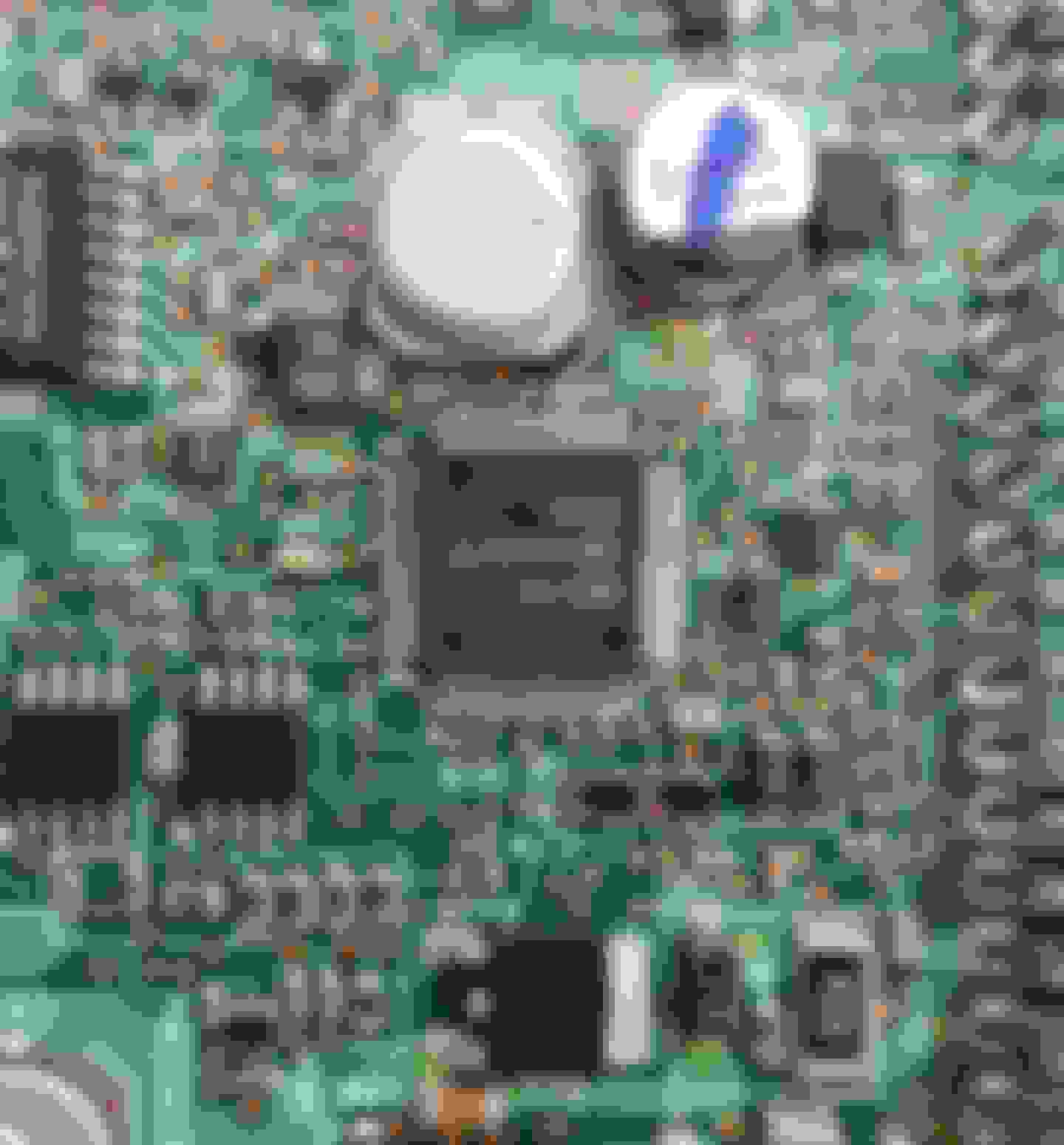
The wheel speed inputs go to this guy. There are a couple of other ports that go directly here too.
I can't remember what goes to this one, but I remember something going here.
Sooo�. what we know as Accel (1.*) and Decel maps (2.*), what if I told you that I don't believe that they ever switch? I don't believe that they are physically wired to do so. Maybe Mitsubishi intended them for this purpose, but then maybe they found that it was too hard to not unsettle the car if there were differences in the maps? Who knows...
Anyway, for those interested, here's my working and results.
As posted earlier, map groups 1 or 2 are selected by testing bit 5 @F080 as seen below.
There are only so many inputs into the 4WD-ECU. A basic summary looks like this:
In the first subroutine of the ROM, input ports get initialised and also, in particular, bits @F080 get set. Thankfully most of them are in sequence from bit 7 down to bit 0, except for 4. I haven't found what sets this yet, or what triggers it. But in this case it's not relevant, although, I'm running out of inputs that it can be.
In the case of bit5, it looks like this.
btst.b #6:16, @PortC_FE97
bne loc_4419:8
my understanding is that if there's an input at port C, then
bset.b #5, r1
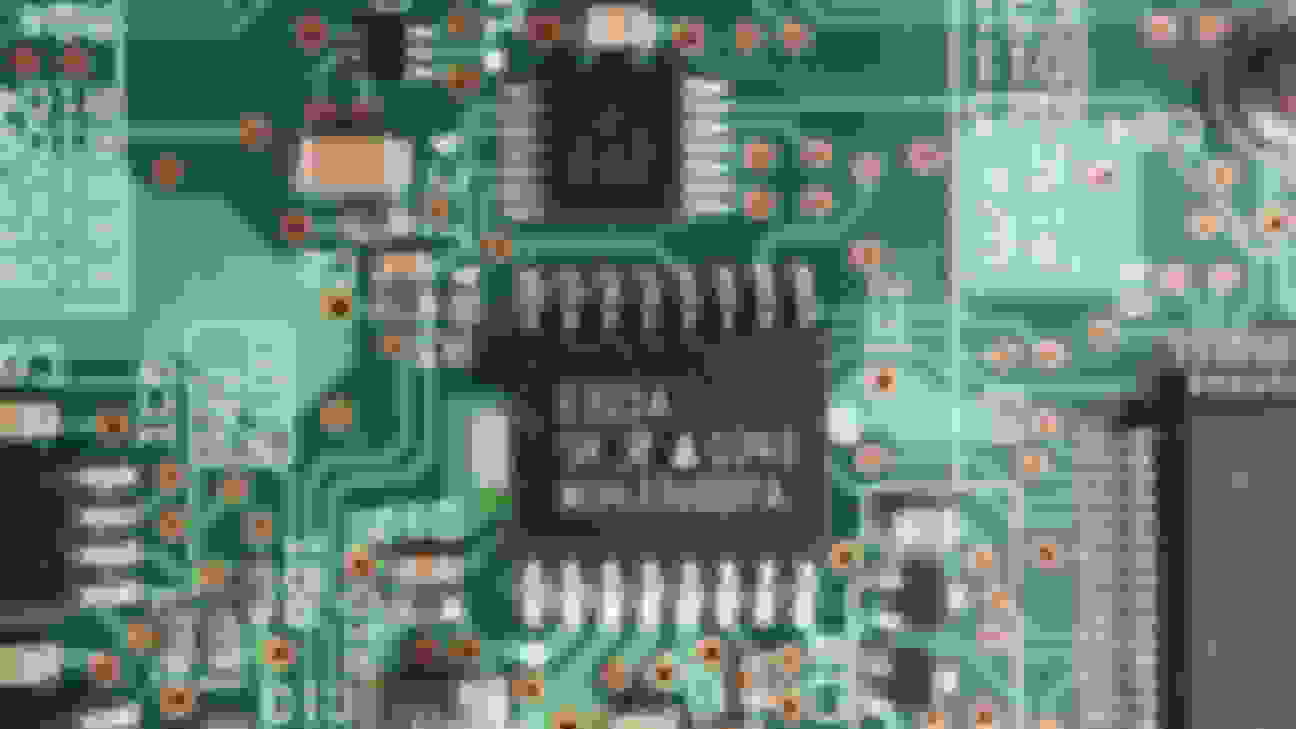
I guess at this point that I should mention that I have been through the H8/539F hardware manual and renamed the addresses to their respective port designation. From this, I believe that bit6@Port C is pin 51. Doing a very quick trace of the PCB, I found this.
On Evo 7's and apparently my JDM Evo 8, there is N/C at plug pin 50. Somewhere along the line (8, 8MR, 9), Mitsubishi grounded this pin (refer to the wiring diagrams). But lets just remember at this point, that plug pin 50 is either no connection or grounded. At no point does it have a switched input. So, have a guess what happened when I logged address F080 and grounded plug pin 50 on the ECU? Yep, a value change of 32 (bit 5).
As mentioned in a previous post, using a modified MUT table and EvoScan to log address F080, I've had the following results: Value change - bit = input
1 - 0 = ABS active
2 - 1 = Brake
4 - 2 = Handbrake
8 - 3 = Pressure sensor > min limit @1019
16 - 4
32 - 5 = pin50
64 - 6 = Mode change
128 - 7 = Battery voltage between limits @1008 and @1009.
Now I've got a couple of other questions to be answered here, and that is because I also noticed other values had changed when I switched the input on plug pin 50. Whether this is because of how the definition is setup in EvoScan or not, I'm not sure. But L&R AYC valves logged as active and the AYC valve current went up to just over 1A (note, no audible change at the hydraulic unit), The oil pressure value went up to 32. Request 02 (ABS monitor) went up to 252.
Out of all the inputs above, I'm yet to have a value from the input set bit5@F080, and given that I've been able to set bit5 manually, I'm pretty certain that although there are 2 groups of switchable maps, they don't actually swap. Going off the logic posted above (and it's the same decision logic for all the duplicated maps/tables groups), there will only every be one path. It appears that Evo 7 and 8's (cars with plug pin 50 N/C) use map groups 2, and 8MR and 9's (cars with plug pin 50 grounded) will use map groups 1.
If anyone has anything to the contrary, or would like to see more code (because my assumptions have every opportunity to be wrong based on my knowledge), please let me know!
Could it be a selectable hardware for discriminate ACD+AYC ecu from Only ACD (RS vs GSR)? Or a porper hardware connection?
At least if you flash a RS rom on a a GSR ecu you log AYC values as you write above (AYC current do fonsoscale 1023mA). Also RS ECU have a different bill of material welded (there are no R shunt, 390mOhm, and relative mosfet for AYC pressure valve and directional valves).
Also for evo 8 RS there are no ABS ecu, the 4 trigger wheel (passive pikup) are directly link to ACD ecu, not repeated by ABS ecu (as for vehicle with ABS).
After trolling the wiring diagrams...again... on Evo 7's, 8's and 9's, Pin 50 is grounded on Non-AYC & Non-ABS vehicles. In Evo 7's, vehicles fitted with AYC & ABS do not have a pin 50 connection. For the rest the diagrams say that Pin 50 should be grounded, however on my JDM 8 with ECU MR580728 rom 400810, this is not the case, pin 50 has no connection.
Will get some comparisons from other models and come back. But, to me this is actually starting to look like that pin 50 is used to set model configuration difference in the early CT9A evo's.
I am thinking there may be a pullup resistor on the pcb at pin 50.
If pin 50 is open on the Evo7 and uses map set 2 (decel) then the effective voltage will be a logical HI.
If pin 50 is wired to GND on the Evo8/9 and uses maps set 1 (ACCEL) then the effective voltage will be a logical LO.
Now ACD pin 38 is the STOP lamp switch input, which should be a logical LO as the lamps will pull the input LO.
This will go to a logical HI when the brake is applied ie a logical HI.
Now imagine adding a wire from pin 38 to pin 50, and you will have ACCEL/DECEL map switching. I think. Feel like doing a test on that blue sky idea Rob?
Hello all,
I'm happy to see this subject caught a bit more attention and I was silently lurking around to see what gets developed from here.
I always felt something is strange with those accel/decel maps as they were never seem to do anything but I chose to copy them over. Never really been into them more. But now the idea of having a strap inside the ECU for this starts to make sense. This probably needs to be tested on a Ralliart ECU. I had one and I can say for sure there is no strap added afterwards. So if anything like this is done, it is somewhere on a PCB pad. So to me, the next question is, is there such a pad that could strap pin 50 and 38? Pin wise, they are very close together, almost one on top of the other
I don't have access to a Ralliart ECU anymore unfortunately...I must have sold it but can't remember haha, but I am doing PCB tests on a MN168749 (Evo 8MR/9 ecu). This ecu according to the diagrams should also be grounded at pin 50.
Dave, I did a lot of poking around to see if I could find any other links to the pin 50 circuit. Being a triple layer, it's very difficult. But all I could find was what I posted.
Having another poke around tonight, it's still all I can find.
From the code and input addresses, I think the brake input is at CPU Pin 60, and I guess this circuit proves that too. Here's a quick poking around trace of plug pin 38.
No continuity or continuity paths between Plug pin 50 and plug pin 38. Sorry Dave. Looking at the circuit above though, i'm curious to see an Evo 7 PCB, considering that the ABS monitor was plug pin 49. I haven't followed pin 48 on this PCB yet.
As for Q3 and Q4, not sure what config this is maybe just 2 transistors (like I have drawn above) in a single package? But here is where they live below.
As for the logics of all this, I'm not sure how the ECU sees it. I guess I could try and look it up, but a small gut feeling tells me that an input pulled low (grounded) could result in a logic 1 input to the ECU. I'll see if I can trace the handbrake at a later time and see what that reveals.
Looking at the circuit i drew (with a clear head and not tired) again this morning, I'm going to have to revisit some things. Diode direction to plug pin 38. I've also noticed that there is another branch off before C46 that I should investigate. I'll also write the actual value of the resistors instead of what I just measured.
Post edit - Yes I had buggered up the diode direction. Pictures edited above with more detail. The branch off of C46 goes no where that I could follow.
Last edited by ROB-80E; Apr 18, 2019 at 02:50 AM.
Reason: Updates made to the above post
After trolling the wiring diagrams...again... on Evo 7's, 8's and 9's, Pin 50 is grounded on Non-AYC & Non-ABS vehicles. In Evo 7's, vehicles fitted with AYC & ABS do not have a pin 50 connection. For the rest the diagrams say that Pin 50 should be grounded, however on my JDM 8 with ECU MR580728 rom 400810, this is not the case, pin 50 has no connection.
Will get some comparisons from other models and come back. But, to me this is actually starting to look like that pin 50 is used to set model configuration difference in the early CT9A evo's.
So far I have confirmation of AYC equipped vehicles from an Evo7GTA, Evo 8, Evo 8MR and an Evo 9 that a connection to pin 50 is absent (contrary to the wiring diagrams).
I'm pretty convinced now that the use of pin50 which sets bit #5 @F080 is used for configuration difference of no AYC/no ABS (eg, RS models). I've done a solid search of the disassembly and there is only one location that sets bit #5 @F080, but as discussed, there's heaps of locations where a 'decision' is made based on the value of this bit.
I guess now I have to figure out what mapset is what. However, going by these instructions:
btst.b #5, @F080
bne
My conclusion is as follows:
If Bit 5 = 0 (AYC - Pin 50 not grounded)
Test bit 5 --> CCR Zbit set to 1 (because value of bit tested is equal to zero)
bne --> checks value of CCR Zbit = 0
Condition = FALSE (follows the false branch which is currently Accel maps (*1.*)).
If Bit 5 = 1 (non-AYC - Pin 50 grounded)
Test bit 5 --> CCR Zbit set to 0 (because value of bit tested is not equal to zero)
bne --> checks value of CCR Zbit = 0
Condition = TRUE (follows the true branch which is currently Decel maps (*2.*)).
NOTE - I will do some physical testing of the above. I'll null one set of maps, and populate another set. Will most likely do Amaps as it's easy to log ACD prop valve current by just depressing the throttle. Can be done stationary.
Soooo, any suggestions on what Accel and Decal maps should be renamed to?
eg1:
Accel --> ACD & AYC
Decel --> ACD only
eg2:
Accel --> With AYC
Decel --> Without AYC
Considering that comment of strapping the brake light switch to Pin50 the next idea is to really make them accel/decel and see if any benefit can be obtained from there.
Considering that comment of strapping the brake light switch to Pin50 the next idea is to really make them accel/decel and see if any benefit can be obtained from there.
S.
I'll be wanting to have a look through the code at all the btst.b #5, @F080 decision points before strapping pin 50 to the brake pedal. There are many factors of the ECU aside from the A, B, C etc tables that could be changed. Eg, AYC function could be disabled. ABS monitor disabled (what does it actually do when ABS is triggered?). Will really need someone with more programming ability than me though to fully understand what is going on. I'm only just managing to bumble my way through. Happy to share my disassembly (will need to be guided through how to).
In the next day or two, i'll confirm (on both an Evo 7 rom and Evo 8/9 rom) what map 'sets' are used when pin 50 is grounded. Hopefully my theory above is correct.
I guess now I have to figure out what mapset is what. However, going by these instructions:
btst.b #5, @F080
bne
My conclusion is as follows:
If Bit 5 = 0 (AYC - Pin 50 not grounded)
Test bit 5 --> CCR Zbit set to 1 (because value of bit tested is equal to zero)
bne --> checks value of CCR Zbit = 0
Condition = FALSE (follows the false branch which is currently Accel maps (*1.*)).
If Bit 5 = 1 (non-AYC - Pin 50 grounded)
Test bit 5 --> CCR Zbit set to 0 (because value of bit tested is not equal to zero)
bne --> checks value of CCR Zbit = 0
Condition = TRUE (follows the true branch which is currently Decel maps (*2.*)).
NOTE - I will do some physical testing of the above. I'll null one set of maps, and populate another set. Will most likely do Amaps as it's easy to log ACD prop valve current by just depressing the throttle. Can be done stationary.
CONFIRMED!
Always awesome when theory becomes practise. The ecu uses the "accel" maps when pin 50 open and the "decel" maps when pin 50 grounded. Tested on both an Evo 7 rom and an Evo 8/9 rom.
Just to reiterate, I will also dig up other decision points where bit #5 @F080 is used within the rom.


 Apr 11, 2019, 05:18 PM