New EVODROID7 EvoScan Android GPS/Logger/Reflashing CarPC Touchscreen Review
 Sep 16, 2013, 06:22 AM
#751

I only just have half a dozen remaining backorders to send out. if you are one of them, you will get a tracking number as soon as its sent. (unless you ordered in the last 2 weeks with non-tracked parcel post, then there is no tracking available but you will still get an automatic dispatch email) if anybody would like me to check order status individually, send me an email hamish at evoscan.com thanks.
 Sep 16, 2013, 07:05 AM
#752
to get the evodroid and the obdii to turn on and off with ignition:
remove the red wire loop from the pin out.
find a 12v source that turns on and off with ignition (per hamish mentioned using the radio power line) and connect to pin#8.
this way the obdi does not always draw power from the battery (pin #7).
remove the red wire loop from the pin out.
find a 12v source that turns on and off with ignition (per hamish mentioned using the radio power line) and connect to pin#8.
this way the obdi does not always draw power from the battery (pin #7).
Sep 16, 2013, 12:17 PM
#753
Evolving Member
iTrader: (10)

Join Date: Sep 2010
Location: Houston
Posts: 291
Likes: 0
Received 0 Likes
on
0 Posts
Hamish. thanks for the update.
Please fix the apk link. I find the tablet screen have a lot of glare in the sun and the lcd back screen not bright enough. So i'd like to use my android phone for this.
please fix apk.
thanks hamish.
Please fix the apk link. I find the tablet screen have a lot of glare in the sun and the lcd back screen not bright enough. So i'd like to use my android phone for this.
please fix apk.
thanks hamish.
Sep 16, 2013, 11:16 PM
#754
Evolving Member
iTrader: (10)
Join Date: Sep 2010
Location: Houston
Posts: 291
Likes: 0
Received 0 Likes
on
0 Posts
ok. I see some gauges made by other ppl such as these:
https://www.evolutionm.net/forums/ev...oscan-gps.html
https://www.evolutionm.net/forums/ec...navigator.html
I've tried changing the files extensions to .xml and loading it with evoscan "load/display gauge layouts" button.
but no luck.
1. how do you load other ppl's gauge layouts onto evoscan?
2. I know how to create 1 template. But how do you create and put together MULTIPLE templates to make 1 layout?
3. how do you upload these layouts to the evodroid7?
Last edited by johnnnyjeans; Sep 16, 2013 at 11:37 PM.
Sep 17, 2013, 01:06 AM
#755
Evolving Member
Hi, when building gauges for the evodroid they cannot be transferred from Evoscan. That was my original mistake...
The Evodroid relies on having two main files:-
1. an image file *.png that represents the gauge layout. As this is a simple image, you can make the gauges as nice looking as you like. It needs to be 800x400 to fit the screen. I created an image in Evoscan and then screen dumped it to a png file.
2. a txt file *.txt in CSV format that defines the gauge needle, its x,y coordinates, sweep angle, start position, etc. etc.
The txt file needs to be renamed to carbon1.txt as this appears to be hard coded into the Evodroid software. The txt file needs to reference the png.
You can use the gauge designer for windows CE that Hamish posted earlier but it puts the needles slightly off.. This software deines the parameters so it is useful from this perspective.
When I get time I will post up the parameters etc. and my sample files. Next step is to get the Evodroid to switch between multiple gauges. It shouldn't be too hard but I haven't had time to look at it in detail.
 Sep 17, 2013, 11:39 AM
#757
Evolving Member
iTrader: (10)
Join Date: Sep 2010
Location: Houston
Posts: 291
Likes: 0
Received 0 Likes
on
0 Posts
HOW TO Turn Openport on/off via ignition.
This is for evo x WITHOUT fast key.
This does not allow your openport to suck out the battery life of your car. Also turn on openport which turns on evoscan on the tablet on ignition.
- take out wire in pin #7
- take out wire in pin #8
- connect new wire to pin #8,
- take same wire and tap into the light geen wire (ACC wire) of iginition harness here.
Last edited by johnnnyjeans; Sep 17, 2013 at 11:42 AM.
Sep 17, 2013, 03:28 PM
#760
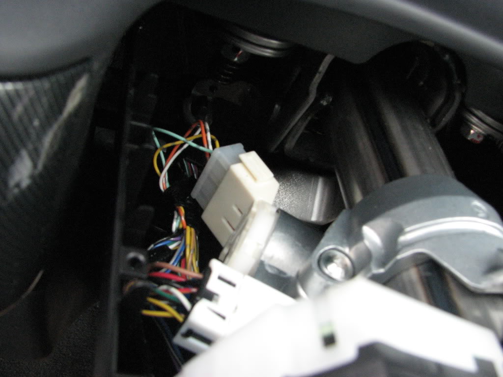
- take out loop wire from OpenPort 3.0DA green connector pin #7 and #8
- connect a length of new wire to OpenPort 3.0DA green connector pin #8, and at the other of this new wire connect it by tapping into the light geen wire (ACC wire) of iginition harness (as shown in the picture).
Sep 17, 2013, 03:36 PM
#761
Another idea, that would be more universal.. instead, you could cut the OBDII pin#16 wire about 2 inches from behind the female OBDII vehicle plug, pin#16 which is direct unswitched power from the battery. and feed power into that cut obdII pin#16 wire (OBDII port side) using the wire from the ACC tap wire.
This would make your OBDII port power on and off with the ignition key.
This would make your OBDII port power on and off with the ignition key.
Last edited by evoscan; Sep 17, 2013 at 03:52 PM.
Sep 17, 2013, 03:51 PM
#763
Evolved Member
iTrader: (33)

Join Date: Jul 2002
Location: Raleigh, Transplanted from Toronto, Canada
Posts: 5,313
Likes: 0
Received 1 Like
on
1 Post
I only just have half a dozen remaining backorders to send out. if you are one of them, you will get a tracking number as soon as its sent. (unless you ordered in the last 2 weeks with non-tracked parcel post, then there is no tracking available but you will still get an automatic dispatch email) if anybody would like me to check order status individually, send me an email hamish at evoscan.com thanks.
Sep 17, 2013, 11:10 PM
#764
Evolving Member
I updated the instructions to try and make it as clear as possible...
- take out loop wire from OpenPort 3.0DA green connector pin #7 and #8
- connect a length of new wire to OpenPort 3.0DA green connector pin #8, and at the other of this new wire connect it by tapping into the light geen wire (ACC wire) of iginition harness (as shown in the picture).
- take out loop wire from OpenPort 3.0DA green connector pin #7 and #8
- connect a length of new wire to OpenPort 3.0DA green connector pin #8, and at the other of this new wire connect it by tapping into the light geen wire (ACC wire) of iginition harness (as shown in the picture).
Okay, tried to get the Evodroid logging wideband and boost.
I connected up the wideband 0-5v to pin 1 and the GM MAP Sensor to pin 2.
The MAP sensor needs +5v to power it so connected that up to pin 4.
I connected both sensor ground wires to pin 6.
I also connected pin 8 to a switched 12v to get cable turned on and off with ignition.
I checked that sensors were working by using a volt meter and checked that pin 4 was +5v........
Good news, the ignition switched on/off the cable...
Bad news, no joy with logging boost or AFR using 0-5v analog.
I tried editing the data settings xml file and replacing it with the evoscan one to see if any of the Evoscan analog data items worked. I logged on all 8 of them and nothing...
My bet (to be confirmed by Hamish) is that the Mitsubishi MUTII EFI.xml file needs to have some additional lines added to allow logging of the 3 analog inputs.
Has anybody got this working?
This is the main reason that I bought this....
Thanks.
Sep 18, 2013, 12:13 AM
#765
Nope you don't need extra lines in the xml datasettings files for Sensor1 thru 3, and Wideband. I got tired of adding those lines into every xml file  so now when you tick them in the DataItem list, they will start logging. I will do some more tests again, and let you know if I find anything I need to fix up.
so now when you tick them in the DataItem list, they will start logging. I will do some more tests again, and let you know if I find anything I need to fix up.