EvoM's First Wire Tuck How To
 Jun 6, 2012, 02:46 PM
#16
Thanks, mang!
 I feel that is everyone's fear when doing a tuck. It definitely crossed my mind, however, the reason why I did a write up was to show that you only have to cut two wires to fully separate each plug! So, if you can solder/shrink wrap those two wires correctly, you don't have to worry about screwing anything up!
I ordered my sleeving.
F6 Wrap-Around Braided Sleeving from:
http://www.cabletiesandmore.com/WrapAroundSleeving.php
I would recommend this over normal loom as it looks a ton better than your standard convoluted plastic/nylon wire loom.
I feel that is everyone's fear when doing a tuck. It definitely crossed my mind, however, the reason why I did a write up was to show that you only have to cut two wires to fully separate each plug! So, if you can solder/shrink wrap those two wires correctly, you don't have to worry about screwing anything up!F6 Wrap-Around Braided Sleeving from:
http://www.cabletiesandmore.com/WrapAroundSleeving.php
I would recommend this over normal loom as it looks a ton better than your standard convoluted plastic/nylon wire loom.
 Jun 6, 2012, 02:54 PM
#17
MY ***!! ....it's fairly simple..... LOL 
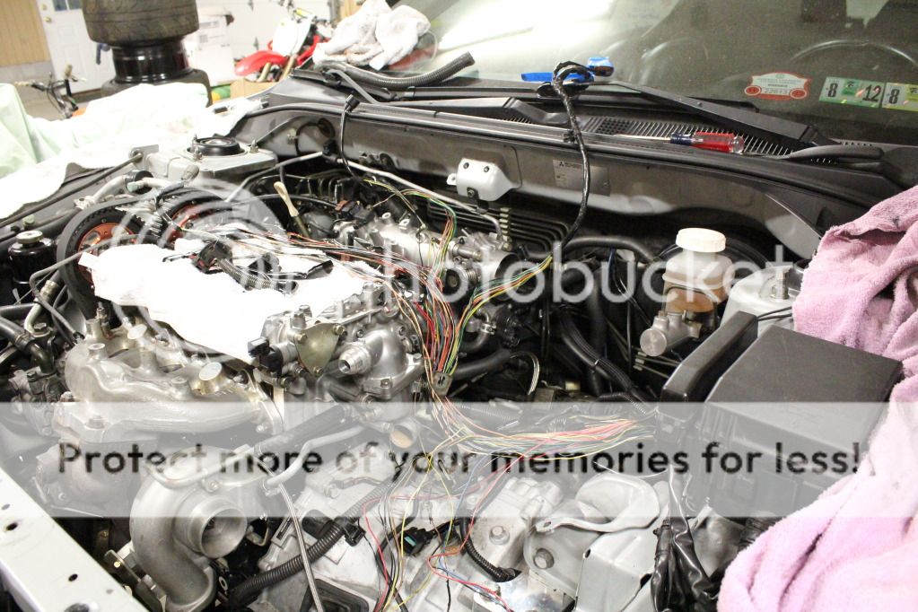
THIS would scare the living living crap out of me to see so many wires all over the place in my engine bay....LOL
Great job documenting it though.....but I just cringed looking at all those wires.... Kudos to you!!!!
THIS would scare the living living crap out of me to see so many wires all over the place in my engine bay....LOL
Great job documenting it though.....but I just cringed looking at all those wires.... Kudos to you!!!!
Jun 6, 2012, 03:36 PM
#18
Now that I look again, that does look a bit stressful. If you have the right mindset going into it I swear it's not that bad!!I'm going to bind the wires together with a few strands of tape and route them tonight as I wait for my loom to come.
Jun 6, 2012, 06:34 PM
#22
Nice work So far buddy, Its worth every effort.
Did a wire tuck with my buddy (fellow evom member)2 weekeds ago, and have to say 10 hours of team work came out flawlessly. If it wasnt for deleting wires such as egr and such we wouldnt have had to cut a single wire. Amazing how retarded Mitsu ran the wires... But sure makes for a fairly easy tuck
BTW that being said, wire tuck is alot cleaner on a evo 8 then 9 Stupid intake cam sensor, you are such a eye sore... lol
Keep up the great work, cant wait to see the end results
Did a wire tuck with my buddy (fellow evom member)2 weekeds ago, and have to say 10 hours of team work came out flawlessly. If it wasnt for deleting wires such as egr and such we wouldnt have had to cut a single wire. Amazing how retarded Mitsu ran the wires... But sure makes for a fairly easy tuck
BTW that being said, wire tuck is alot cleaner on a evo 8 then 9
Stupid intake cam sensor, you are such a eye sore... lol Keep up the great work, cant wait to see the end results
Jun 6, 2012, 07:08 PM
#23
Mitsubishi ran the wires in a manner that makes it fairly easy to service the car. It's actually much better than a wire tuck...it just doesn't look very good.
Just some tips I can offer to provide a high reliability harness:
1. Don't solder anything.
Use barrel crimps like OEM. Solder creates a section of wire that is stiff and can fail from vibration.
2. Insulate splices like the OEM (liquid electrical tape covered with electrical tape folded onto itself and then wrapped with electrical tape) or use heat shrink tubing with an adhesive liner. Standard heat shrink tubing DOES NOT seal the joint from liquids.
I would also disagree with the idea of running/looming everything individually. You can run the wires as a harness that will completely tuck out of view with only a little more work. Having the wires as a harness will greatly strengthen the harness and prevent damaging loose wires.
Last edited by 03whitegsr; Jun 6, 2012 at 07:14 PM.
Jun 6, 2012, 08:24 PM
#24
Nice work So far buddy, Its worth every effort.
Did a wire tuck with my buddy (fellow evom member)2 weekeds ago, and have to say 10 hours of team work came out flawlessly. If it wasnt for deleting wires such as egr and such we wouldnt have had to cut a single wire. Amazing how retarded Mitsu ran the wires... But sure makes for a fairly easy tuck
BTW that being said, wire tuck is alot cleaner on a evo 8 then 9 Stupid intake cam sensor, you are such a eye sore... lol
Keep up the great work, cant wait to see the end results
Did a wire tuck with my buddy (fellow evom member)2 weekeds ago, and have to say 10 hours of team work came out flawlessly. If it wasnt for deleting wires such as egr and such we wouldnt have had to cut a single wire. Amazing how retarded Mitsu ran the wires... But sure makes for a fairly easy tuck
BTW that being said, wire tuck is alot cleaner on a evo 8 then 9
Stupid intake cam sensor, you are such a eye sore... lol Keep up the great work, cant wait to see the end results
And thankfully I have a VIII.Mitsubishi ran the wires in a manner that makes it fairly easy to service the car. It's actually much better than a wire tuck...it just doesn't look very good.
Just some tips I can offer to provide a high reliability harness:
1. Don't solder anything.
Use barrel crimps like OEM. Solder creates a section of wire that is stiff and can fail from vibration.
2. Insulate splices like the OEM (liquid electrical tape covered with electrical tape folded onto itself and then wrapped with electrical tape) or use heat shrink tubing with an adhesive liner. Standard heat shrink tubing DOES NOT seal the joint from liquids.
I would also disagree with the idea of running/looming everything individually. You can run the wires as a harness that will completely tuck out of view with only a little more work. Having the wires as a harness will greatly strengthen the harness and prevent damaging loose wires.
.I agree that the car is fairly easy to service, however, my plan was to make the wires just as accessible while having them out of the way. My idea of a "tuck" is just that; I want to re-route the wires in such a way that they're hidden, however, will still be just as easy to work with as the factory harness, rather than others who make their harness impossible to work with when on the car.
1. I see what you're saying, however, the only problems my harness had were due to the factory barrel crimps, in a few different places. The places in which I chose to solder were not near any bends, and were efficiently secured so that the (two) wires I soldered would see limited vibration. But again, two or three broken/worn barrel crimps were the reason behind a few burnt wires and draws.
2. I hear you on the standard heat shrink tubing. Every place I used head shrink tubing I was sure to have two coats of electrical tape over it, although I didn't use the liquid stuff.
To address your last point, I only said that initially, as I need to de-loom the entire harness and run each plug separately in order to combine it in such a way that it acts as a whole harness. The pictures from tonight show how I ran them separately, and then made one big harness out of it!
The response was very helpful!
Jun 6, 2012, 09:06 PM
#25
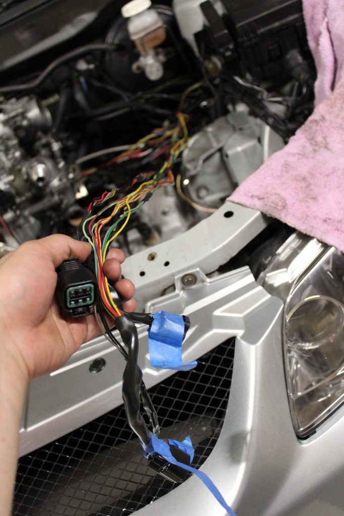
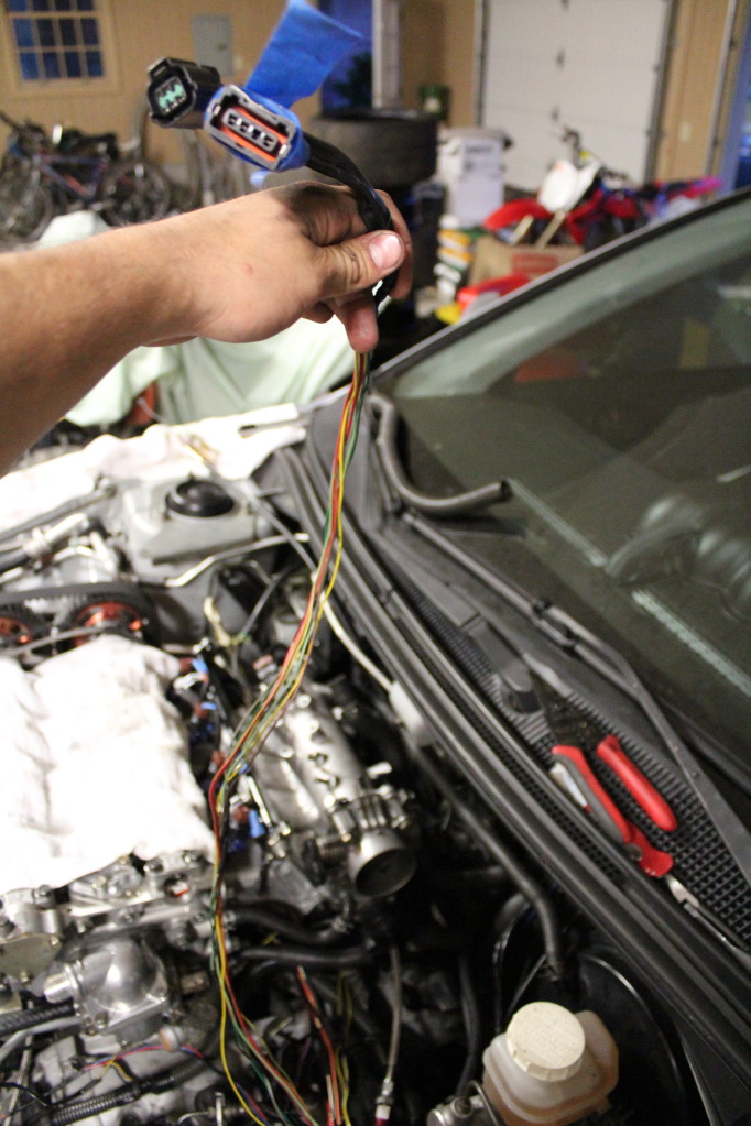
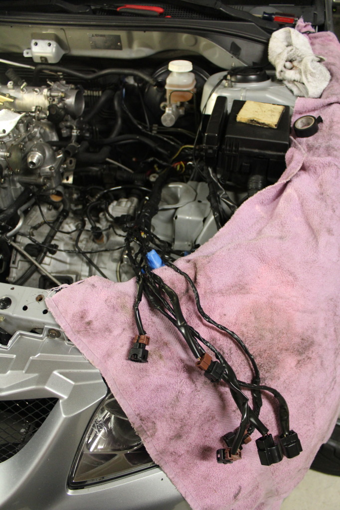
I worked on the harness a little tonight.
I thought this was hilarious. A 3ft wire that literally only needed to be about 8".
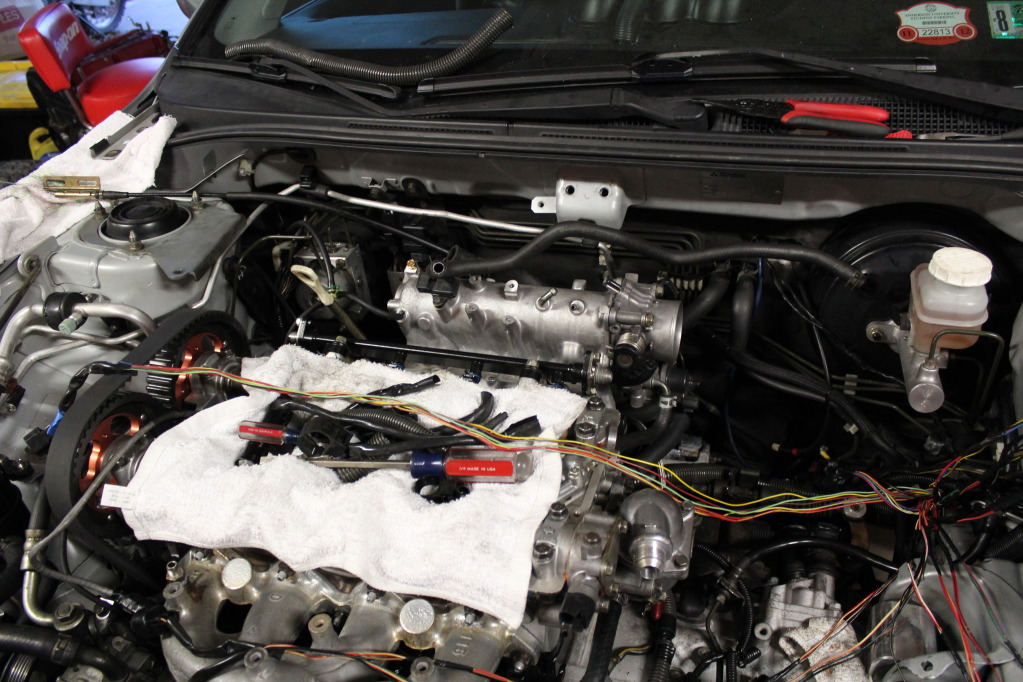
I first ran each separated harness in their "hidden" locations.
Injectors:
CAS:
MAP Sensor:
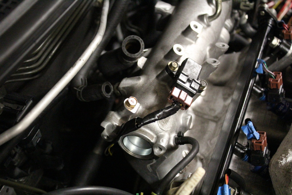
02 Sensor:
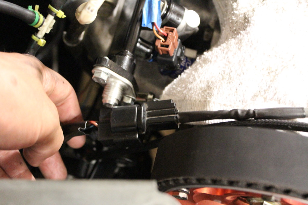
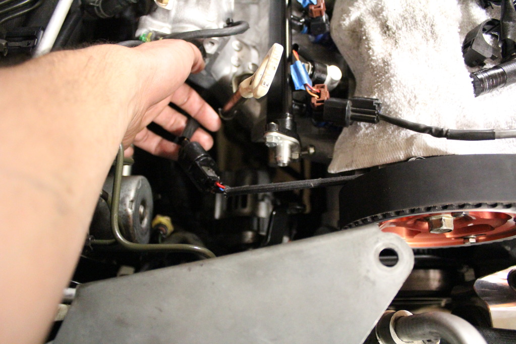
In doing this, I noticed there were three plugs that were WAY too long. Because I don't want to cut any wires for reliability purposes, I chose to neatly rap up their excess and place it in the main harness. It really helped clean everything up without cutting anything.
One plug that was far too long:
And the other two:
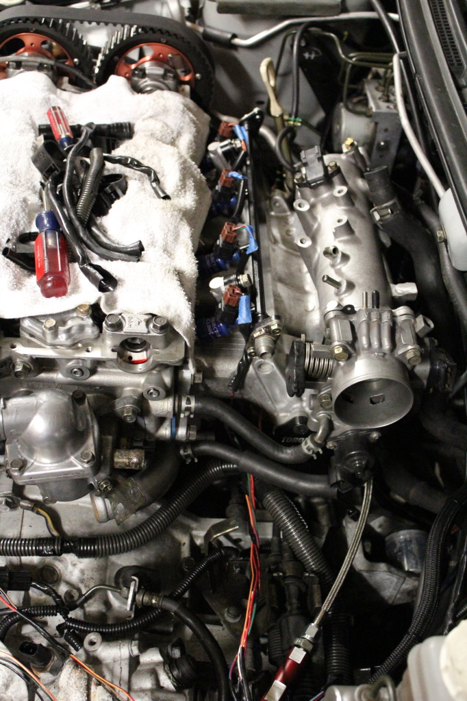
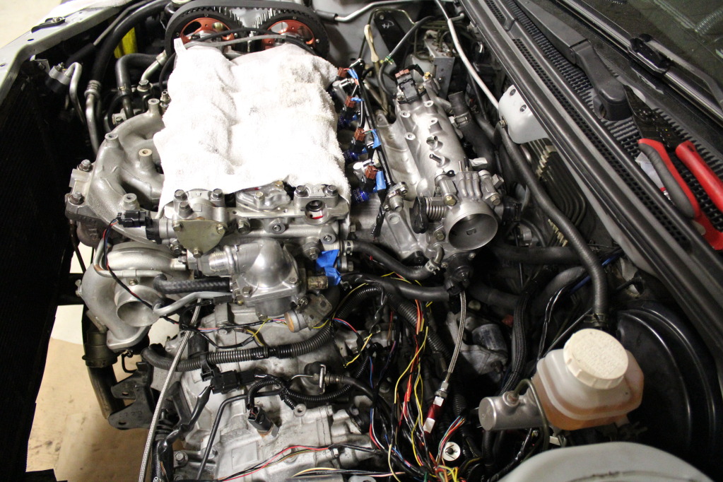
Everything routed and hooked up for a test fit:
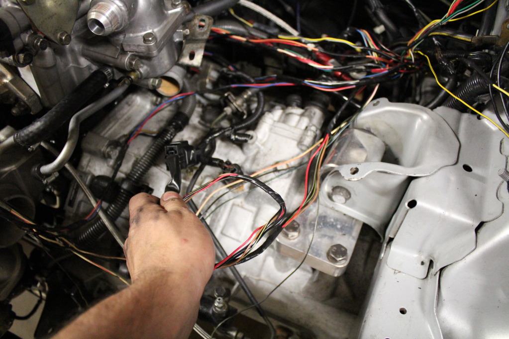
After everything was hidden, I then connected everything into a "main harness" type of deal to add strength to the harness.
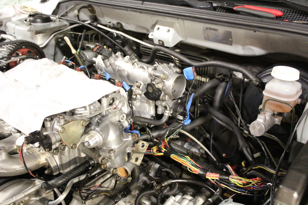
I then took it all back of and did a pre-loom wrap job:
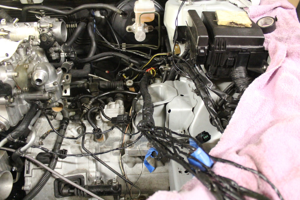
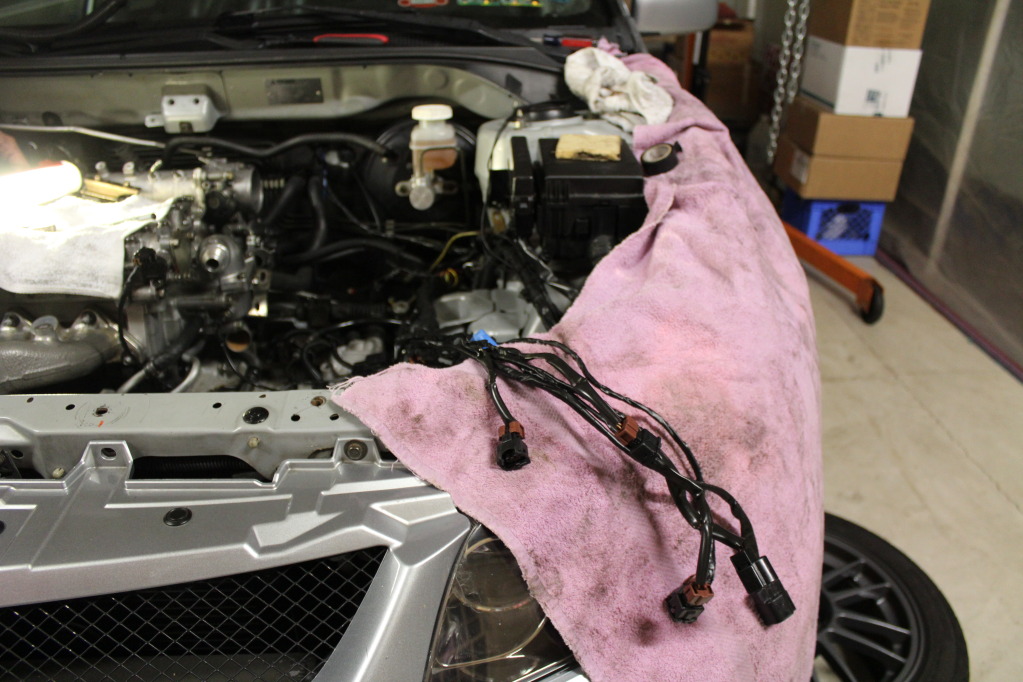
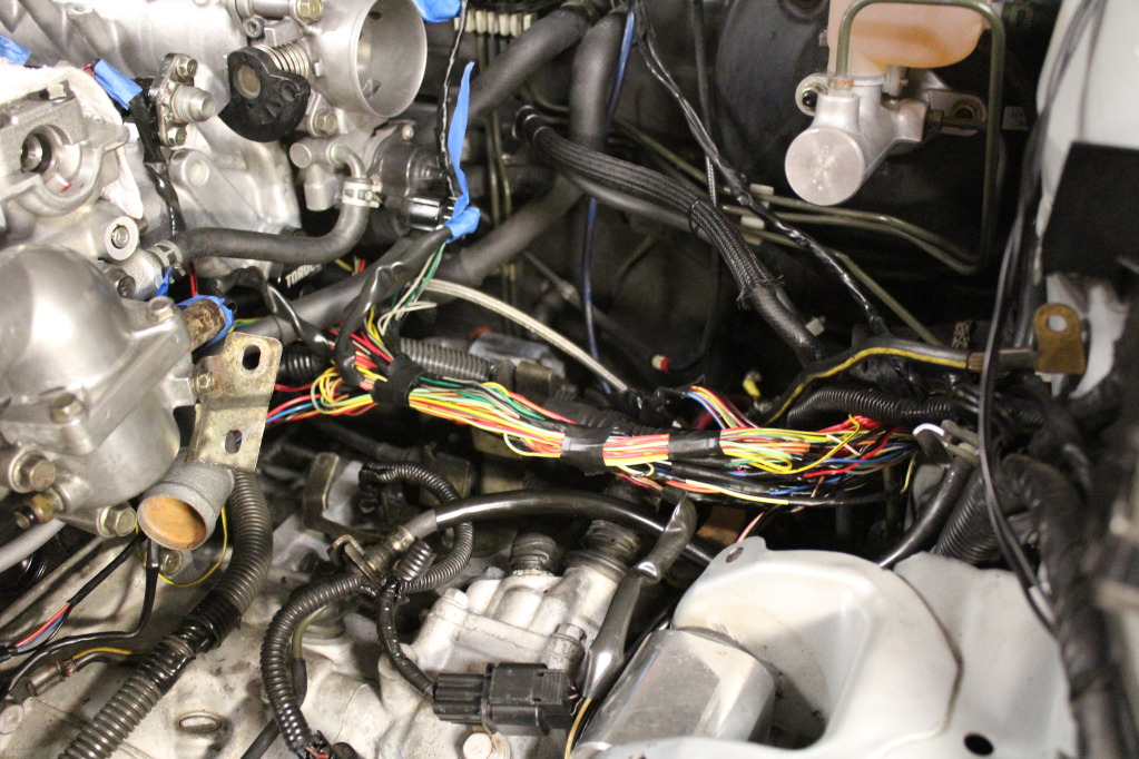
This is the final routing I chose for everything, but didn't feel like re-routing it again after I had sealed it all up. You get the idea, nonetheless.
I thought this was hilarious. A 3ft wire that literally only needed to be about 8".
I first ran each separated harness in their "hidden" locations.
Injectors:
CAS:
MAP Sensor:
02 Sensor:
In doing this, I noticed there were three plugs that were WAY too long. Because I don't want to cut any wires for reliability purposes, I chose to neatly rap up their excess and place it in the main harness. It really helped clean everything up without cutting anything.
One plug that was far too long:
And the other two:
Everything routed and hooked up for a test fit:
After everything was hidden, I then connected everything into a "main harness" type of deal to add strength to the harness.
I then took it all back of and did a pre-loom wrap job:
This is the final routing I chose for everything, but didn't feel like re-routing it again after I had sealed it all up. You get the idea, nonetheless.
Jun 6, 2012, 09:08 PM
#26
Evolving Member
iTrader: (13)
Join Date: May 2006
Location: utah
Posts: 310
Likes: 0
Received 0 Likes
on
0 Posts
If you need any more advice or just someone to vent to about this, hit me up. I've put myself through this before on my galant.
went from this
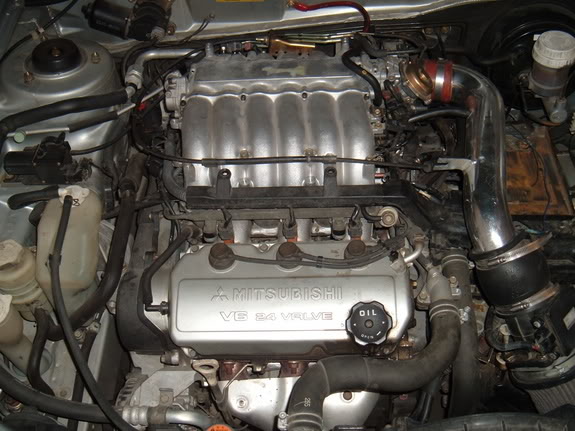
to this
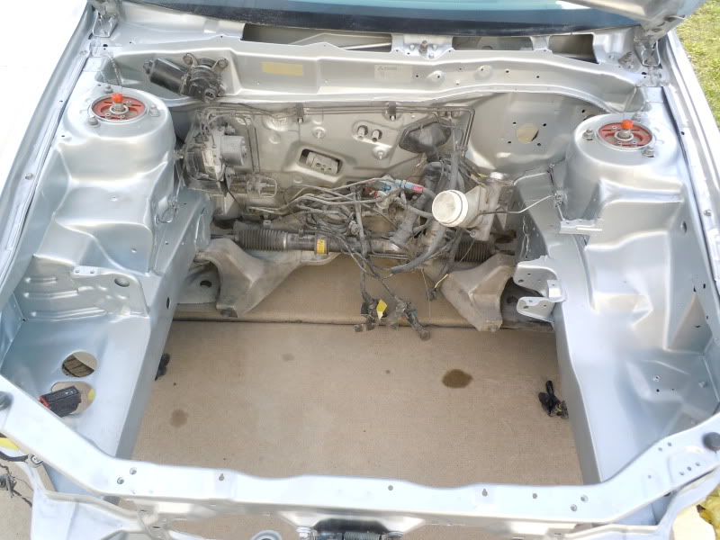
and ended up with this
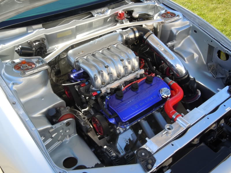
my galant harness had 92 wires in it exiting the firewall and I consolidated them down to 56 functional wires while retaining the shielding on the cam and crank sensors along with knock and other system components. It was especially fun moving the fusebox out of the engine bay. Like Mike said, soldering can create a mess of unexpected variables...unless you are an electrician and/or understand electronic principles. I thought of my wire tuck as easy since I'm an F-16 electrician. I used all virtually zero ohm environmental splices and used self bonding or mil spec heat shrink as to prevent any type of corrosion buildup in the harness. My wire tuck went beyond the spectrum of normal though as I used aluminel wire to reduce weight and provide greater lifespan with greater flexibility. Good luck on your endeavors and I cant wait to see when you're all done. I plan to tuck my evo as soon as I get back from my TDY and leave.
went from this
to this
and ended up with this
my galant harness had 92 wires in it exiting the firewall and I consolidated them down to 56 functional wires while retaining the shielding on the cam and crank sensors along with knock and other system components. It was especially fun moving the fusebox out of the engine bay. Like Mike said, soldering can create a mess of unexpected variables...unless you are an electrician and/or understand electronic principles. I thought of my wire tuck as easy since I'm an F-16 electrician. I used all virtually zero ohm environmental splices and used self bonding or mil spec heat shrink as to prevent any type of corrosion buildup in the harness. My wire tuck went beyond the spectrum of normal though as I used aluminel wire to reduce weight and provide greater lifespan with greater flexibility. Good luck on your endeavors and I cant wait to see when you're all done. I plan to tuck my evo as soon as I get back from my TDY and leave.
Jun 6, 2012, 09:20 PM
#27
my galant harness had 92 wires in it exiting the firewall and I consolidated them down to 56 functional wires while retaining the shielding on the cam and crank sensors along with knock and other system components. It was especially fun moving the fusebox out of the engine bay. Like Mike said, soldering can create a mess of unexpected variables...unless you are an electrician and/or understand electronic principles. I thought of my wire tuck as easy since I'm an F-16 electrician. I used all virtually zero ohm environmental splices and used self bonding or mil spec heat shrink as to prevent any type of corrosion buildup in the harness. My wire tuck went beyond the spectrum of normal though as I used aluminel wire to reduce weight and provide greater lifespan with greater flexibility. Good luck on your endeavors and I cant wait to see when you're all done. I plan to tuck my evo as soon as I get back from my TDY and leave.
Thanks for the advice. I'm surely no electrician
. Wiring is one of those things that I was afraid of, so I pushed myself onto this project and I found out that I really enjoy doing it!I literally only joined two wires in this entire project, as my goal was to "tuck" rather than to completely eliminate all sight of wiring like you did (which looks incredible).
Because I saw how the factory clamps caused issues on my application, I carefully soldered them, however, I solder in a different way than most folks (I think), in that I'll gently push the wires together, and only use a small amount of solder. However, I make sure the solder gets in-between the individual wires rather than having a big glob of solder than can easily break off due to vibration, like you guys were saying.
With only cutting/joining two wires, I was extremely pleased with the outcome of how I routed things, and was also very happy about how the harness came together in such a way that I still have a "main harness", so to speak, so it's not just individual wires running all over my bay.
If you have any advice I'd be glad to hear it, man!
Jun 6, 2012, 09:30 PM
#28
Evolving Member
iTrader: (13)
Join Date: May 2006
Location: utah
Posts: 310
Likes: 0
Received 0 Likes
on
0 Posts
Thanks on the compliments man. Once all done it was well worth it and I can with confidence utter the words "I believe I have the best v6 galant engine bay". But I worked my *** off for it and didnt buy it ya know. So cuddos to you for taking on this project without having done one before, THATS admirable!
The one thing I dont like about soldering in engine bays is the fact that cold solder joints can be easily created while soldering without you knowing until the wire breaks . On top of that, if you get a cold solder joint that doesnt break it actually massively increases the resistance in that circuit because of not having a complete and comprehensive connection. This can lead to component, sensor, or worse ecu issues. Some of the circuits, no most of the circuits on these modern cars are resistance seeking and constantly rely on those signals to be correct and not varying outside of their designed realm of operation. Those splices me and Mike were talking about allow for that resistance not to change to the point of creating harm for components. With soldering, did you "tin" the wires being connected before soldering them together?
The one thing I dont like about soldering in engine bays is the fact that cold solder joints can be easily created while soldering without you knowing until the wire breaks . On top of that, if you get a cold solder joint that doesnt break it actually massively increases the resistance in that circuit because of not having a complete and comprehensive connection. This can lead to component, sensor, or worse ecu issues. Some of the circuits, no most of the circuits on these modern cars are resistance seeking and constantly rely on those signals to be correct and not varying outside of their designed realm of operation. Those splices me and Mike were talking about allow for that resistance not to change to the point of creating harm for components. With soldering, did you "tin" the wires being connected before soldering them together?
Jun 6, 2012, 09:37 PM
#29
Thanks on the compliments man. Once all done it was well worth it and I can with confidence utter the words "I believe I have the best v6 galant engine bay". But I worked my *** off for it and didnt buy it ya know. So cuddos to you for taking on this project without having done one before, THATS admirable!
The one thing I dont like about soldering in engine bays is the fact that cold solder joints can be easily created while soldering without you knowing until the wire breaks . On top of that, if you get a cold solder joint that doesnt break it actually massively increases the resistance in that circuit because of not having a complete and comprehensive connection. This can lead to component, sensor, or worse ecu issues. Some of the circuits, no most of the circuits on these modern cars are resistance seeking and constantly rely on those signals to be correct and not varying outside of their designed realm of operation. Those splices me and Mike were talking about allow for that resistance not to change to the point of creating harm for components. With soldering, did you "tin" the wires being connected before soldering them together?
The one thing I dont like about soldering in engine bays is the fact that cold solder joints can be easily created while soldering without you knowing until the wire breaks . On top of that, if you get a cold solder joint that doesnt break it actually massively increases the resistance in that circuit because of not having a complete and comprehensive connection. This can lead to component, sensor, or worse ecu issues. Some of the circuits, no most of the circuits on these modern cars are resistance seeking and constantly rely on those signals to be correct and not varying outside of their designed realm of operation. Those splices me and Mike were talking about allow for that resistance not to change to the point of creating harm for components. With soldering, did you "tin" the wires being connected before soldering them together?
), I'm not sure what you mean by "tinning" the wires.The "technique" I came up with after some thinking consisted of pushing the wires straight together and heating the wire before actually putting the solder on the wire to ensure that the solder would make it's way all of the way through the wire.