HowTo: Logging Wideband AFR via Rear O2 ECU ADC Input (Logging AFR without serial)
 Aug 26, 2009, 08:42 PM
#1
Evolved Member
Thread Starter
iTrader: (4)

Join Date: Feb 2008
Location: Edmonton, Alberta
Posts: 610
Likes: 0
Received 0 Likes
on
0 Posts
HowTo: Logging Wideband AFR via Rear O2 ECU ADC Input (Logging AFR without serial)
HOW TO:
Logging Wideband AFR via Rear O2 ECU ADC Input (Logging AFR without serial)
Parts Needed:
- Wideband O2 (I used an AEM UEGO)
Tools Required:
- OpenPort 2.0 Cable
- ECUFlash
- EvoScan
(I imagine Cobb AP and ATR could do this as well, but I won't go into details)
- Laptop
- Flashlight
- Electrical Tape
- Knife
- Wire Taps
- Soldering Iron/Solder
- Philips Screwdriver
- 10mm & 14mm Sockets
- Ratchet
Recommended Number of People
- Hopefully 1, though an extra set of hands is nice!
Difficulty
- 3 out of 10 if you've already got ECUFlash installed
Time to complete
- Give yourself a bit of time, especially if you've never removed the seat or dash trim. Call it one hour with experience with the dash trim.
Step by Step Instructions
0 - First off, you need to remove the rear O2 sensor from the exhaust stream. When you disable the O2 sensor, you disable its heater and as a result the sensor will be damaged if exposed to exhaust temperatures. I will not go into details on how to do this, because you should have it done already before starting this tutorial. You can either remove the O2 sensor from the car completely or just wrap it and tie it up (as I did) out of the way.
Then, it helps to have a bit of understanding as to what we are trying to accomplish. Basically, as the below diagram shows, the ECU receives an analog signal from the O2 sensor, which is then converted into a digital signal for the ECU to use. What we want to do is replace the O2 sensor signal with a WB sensor signal so that we can log it in EvoScan. If you look at the diagram, all we are really doing is replacing the yellow wire's input, so that it is sending your WB signal instead.


Part I
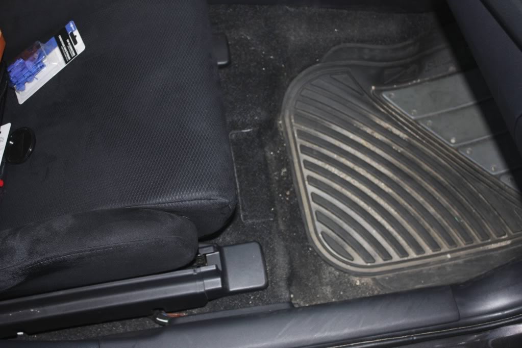
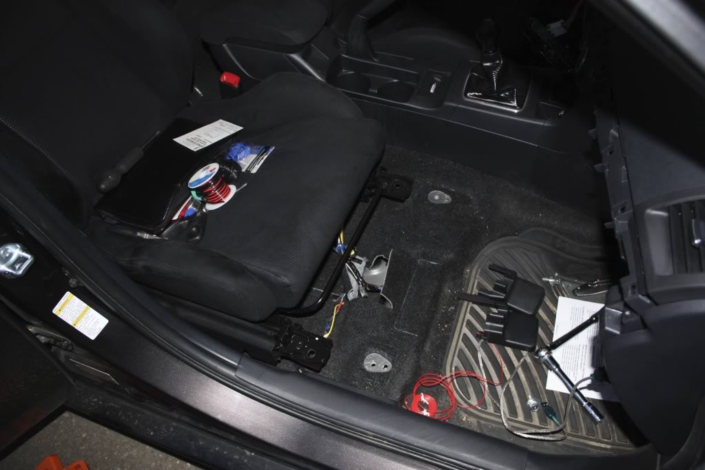
1 - Here is where we are working. The Rear O2 sensor wiring runs through a grommet under the passenger seat and is (sort of) accessible through a flap in the carpet. If you have small hands, it is a little easier. Make sure you move the seat all the way back!
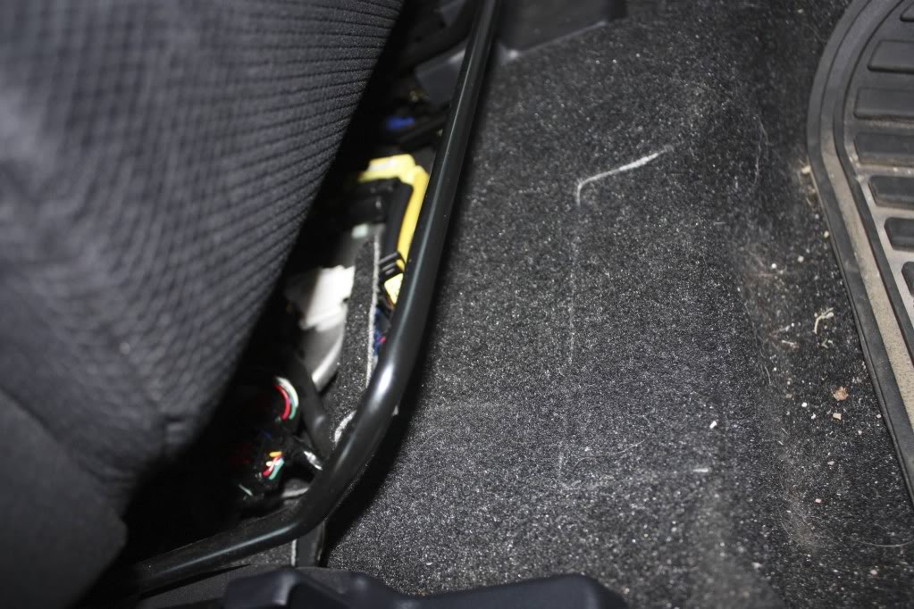
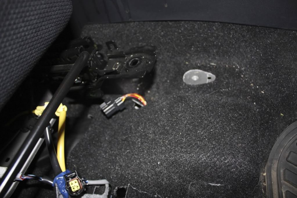
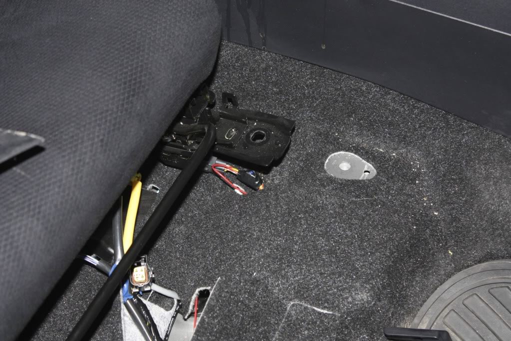
2 - Unplug the O2 sensor harness and tape the O2 sensor side nicely out of the way, so it doesn't rattle around.
3 - Unclip the other connector from it's nice little holding spot (it probably already came off while you were unplugging the connectors) so you can actually work with it.
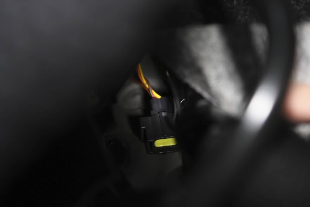
4 - You should be able to see the yellow wire that we are going through all this trouble to get to. At this point, you'll probably decide that this was an easy project! Then you'll realize that there is no way that you can get that wire tapped in that tiny *** amount of space.
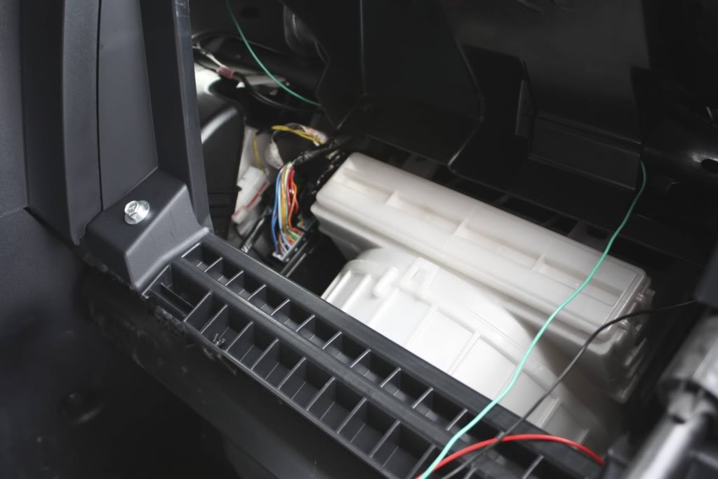
5 - I ended up unbolting [14mm] the passenger seat (no need to unclip harnesses, we aren't going far) and sliding it back as far as possible to give a bit more working room.
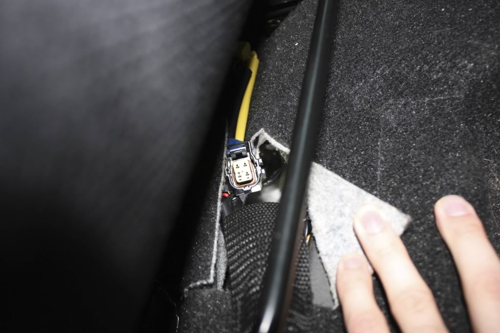
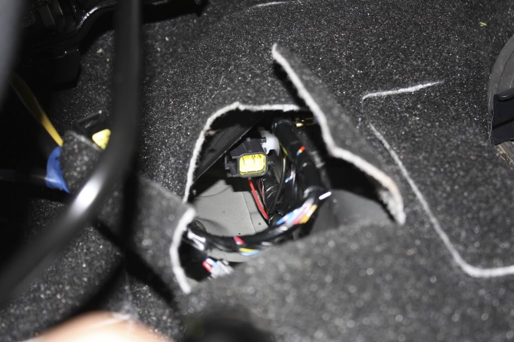
6 - Once the seat is move back a bit, you'll realize that there still isn't any room, as the heater duct is what is actually causing you problems. Fortunately, with the seat out of the way, a small (unnoticeable) incision into the carpet can pull the wires and harness up into a workable amount of space. Just cut an area so that you can reach in and find the connector, then pull it through.
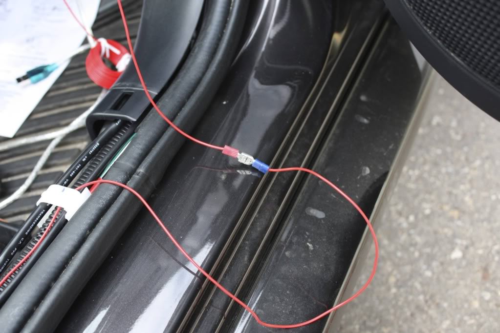
7 - Tap into the yellow wire. I used taps, some will solder. It isn't a high current wire, the tap should be fine. Then, push the connector back down and clip it back into it's holding clip.
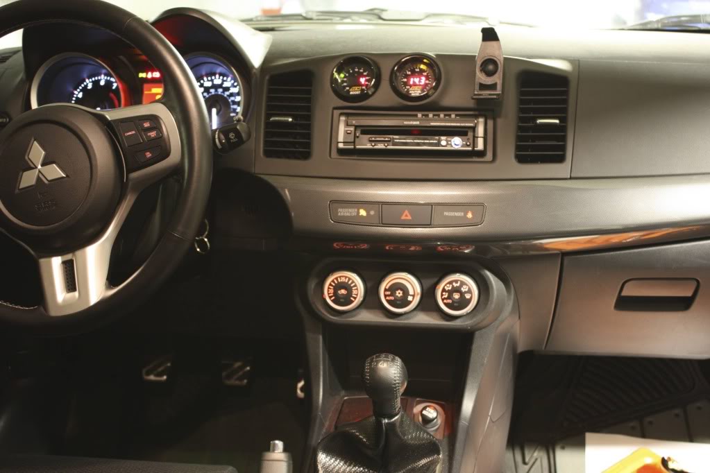
8 - What are we tapping/vamping into? Well, the 0-5V Analog output of you Wideband O2 Sensor. I have an AEM UEGO, which has a white wire (pictured) coming off the back of the gauge. This is the wire I need to get to the yellow wire. Depending on where your gauge is located, your routing method will be different.
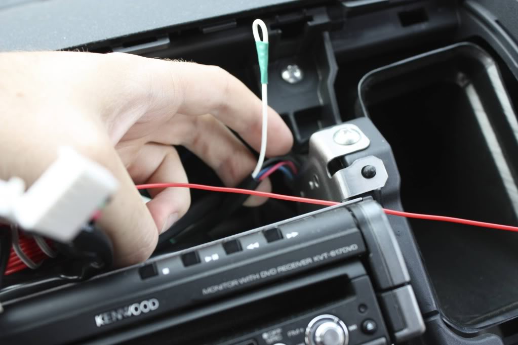
9 - In my case, I used red wire to extend the yellow wire connection up the side of the passenger area, up the corner and behind the glovebox. Also, I added a quick disconnect so that I could go back to stock if necessary without tearing everything apart again. I already have a ton of wires routed this way from my stereo install, so it wasn't like it was new to me. For those who haven't done this, don't be scared. Pinch the glovebox in, unclip the hydraulic thing from the glovebox and pull the glovebox out. There are 4 screws and a clip that need to be removed, but then you can route any wire you want! (The green/black wires are my serial cable, which stopped working leading to this project)
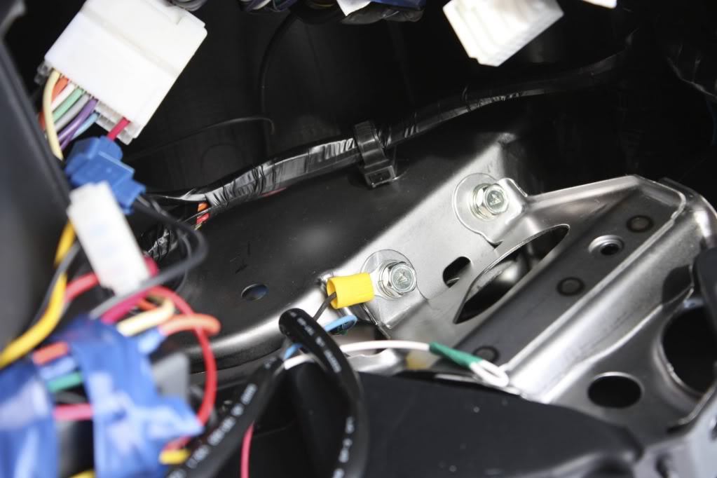
10 - Behind the stereo area (which is where I have my gauges, you might have a different setup), the red wire was soldered to the white analog wire, and while I was there I relocated the UEGO ground. Ever since I installed it, there was a high pitched whine that irritated the hell out of me but I couldn't be bothered to open this up again. It was originally grounded to the stereo ground, I simply relocated it to a bolt [10mm] (visible in the picture).
11 - Reinstalled the gauges and trim, and done!
Part II
Now that we have an input into the ECU, we need to actually record from it! Our outline is: disable rear O2 sensor, setup EvoScan to record input, log away!
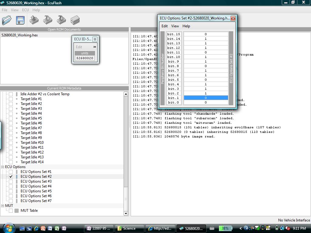
1 - Disabling the rear O2 sensor is done by toggling bit.1 of ECU Options #2. Simply open up your ROM in ECUFlash, find the table "ECU Options #2" and use the "[" key to toggle bit.1 . This updated ROM needs to be flashed to the car. This "Disable" of the O2 sensor DOES NOT necessarily mean you won't get CELs. What we really need is an O2 simulator patch, which is not yet available for the X. I have a CEL, but it doesn't really matter, the future will get rid of that for us.
2 - EvoScan time! First, we need to do some math. Find the documentation for you gauge/wideband, we need to determine the formula that relates the analog voltage to what the AFR is. Look at the documentation, if it lists a transfer function, that's what we want. If not, find the formula yourself by looking at the 0V and 5V AFR and working it out.
For the new AEM Analog WB Gauge, AFR = 2.375*V + 7.3125
For my AEM UEGO Gauge, AFR = 2*V + 10.
This is almost the formula EvoScan needs. We can't input "V" into EvoScan, we need it to be an ECU parameter. Fortunately, we just tapped into the ADC! Therefore,
V = 5*ADC/1023
In my 52680020 ROM, the ADC Memory Address is a 2byte value at 0x80934E.
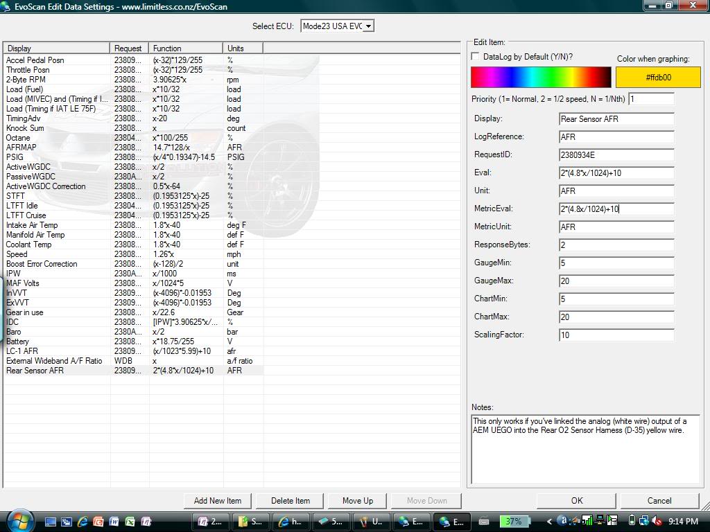
After testing out the new logging parameter, I had to adjust the formula a bit to get it to actually match the proper gauge output. My output was reading too high, so I had to offset the calculation slightly. My final formula and information is shown in the pictures.
Therefore, what we actually put in EvoScan looks like this. To get this screen, select the 2008 Mode23 USDM EvoX from the dropdown box, right click where the logging items are and edit. Click Add New at the bottom, and enter the details.
3 - Finally, logging time!
Logging Wideband AFR via Rear O2 ECU ADC Input (Logging AFR without serial)
Parts Needed:
- Wideband O2 (I used an AEM UEGO)
Tools Required:
- OpenPort 2.0 Cable
- ECUFlash
- EvoScan
(I imagine Cobb AP and ATR could do this as well, but I won't go into details)
- Laptop
- Flashlight
- Electrical Tape
- Knife
- Wire Taps
- Soldering Iron/Solder
- Philips Screwdriver
- 10mm & 14mm Sockets
- Ratchet
Recommended Number of People
- Hopefully 1, though an extra set of hands is nice!
Difficulty
- 3 out of 10 if you've already got ECUFlash installed
Time to complete
- Give yourself a bit of time, especially if you've never removed the seat or dash trim. Call it one hour with experience with the dash trim.
Step by Step Instructions
0 - First off, you need to remove the rear O2 sensor from the exhaust stream. When you disable the O2 sensor, you disable its heater and as a result the sensor will be damaged if exposed to exhaust temperatures. I will not go into details on how to do this, because you should have it done already before starting this tutorial. You can either remove the O2 sensor from the car completely or just wrap it and tie it up (as I did) out of the way.
Then, it helps to have a bit of understanding as to what we are trying to accomplish. Basically, as the below diagram shows, the ECU receives an analog signal from the O2 sensor, which is then converted into a digital signal for the ECU to use. What we want to do is replace the O2 sensor signal with a WB sensor signal so that we can log it in EvoScan. If you look at the diagram, all we are really doing is replacing the yellow wire's input, so that it is sending your WB signal instead.
Part I
1 - Here is where we are working. The Rear O2 sensor wiring runs through a grommet under the passenger seat and is (sort of) accessible through a flap in the carpet. If you have small hands, it is a little easier. Make sure you move the seat all the way back!
2 - Unplug the O2 sensor harness and tape the O2 sensor side nicely out of the way, so it doesn't rattle around.
3 - Unclip the other connector from it's nice little holding spot (it probably already came off while you were unplugging the connectors) so you can actually work with it.
4 - You should be able to see the yellow wire that we are going through all this trouble to get to. At this point, you'll probably decide that this was an easy project! Then you'll realize that there is no way that you can get that wire tapped in that tiny *** amount of space.
5 - I ended up unbolting [14mm] the passenger seat (no need to unclip harnesses, we aren't going far) and sliding it back as far as possible to give a bit more working room.
6 - Once the seat is move back a bit, you'll realize that there still isn't any room, as the heater duct is what is actually causing you problems. Fortunately, with the seat out of the way, a small (unnoticeable) incision into the carpet can pull the wires and harness up into a workable amount of space. Just cut an area so that you can reach in and find the connector, then pull it through.
7 - Tap into the yellow wire. I used taps, some will solder. It isn't a high current wire, the tap should be fine. Then, push the connector back down and clip it back into it's holding clip.
8 - What are we tapping/vamping into? Well, the 0-5V Analog output of you Wideband O2 Sensor. I have an AEM UEGO, which has a white wire (pictured) coming off the back of the gauge. This is the wire I need to get to the yellow wire. Depending on where your gauge is located, your routing method will be different.
9 - In my case, I used red wire to extend the yellow wire connection up the side of the passenger area, up the corner and behind the glovebox. Also, I added a quick disconnect so that I could go back to stock if necessary without tearing everything apart again. I already have a ton of wires routed this way from my stereo install, so it wasn't like it was new to me. For those who haven't done this, don't be scared. Pinch the glovebox in, unclip the hydraulic thing from the glovebox and pull the glovebox out. There are 4 screws and a clip that need to be removed, but then you can route any wire you want! (The green/black wires are my serial cable, which stopped working leading to this project)
10 - Behind the stereo area (which is where I have my gauges, you might have a different setup), the red wire was soldered to the white analog wire, and while I was there I relocated the UEGO ground. Ever since I installed it, there was a high pitched whine that irritated the hell out of me but I couldn't be bothered to open this up again. It was originally grounded to the stereo ground, I simply relocated it to a bolt [10mm] (visible in the picture).
11 - Reinstalled the gauges and trim, and done!
Part II
Now that we have an input into the ECU, we need to actually record from it! Our outline is: disable rear O2 sensor, setup EvoScan to record input, log away!
1 - Disabling the rear O2 sensor is done by toggling bit.1 of ECU Options #2. Simply open up your ROM in ECUFlash, find the table "ECU Options #2" and use the "[" key to toggle bit.1 . This updated ROM needs to be flashed to the car. This "Disable" of the O2 sensor DOES NOT necessarily mean you won't get CELs. What we really need is an O2 simulator patch, which is not yet available for the X. I have a CEL, but it doesn't really matter, the future will get rid of that for us.
2 - EvoScan time! First, we need to do some math. Find the documentation for you gauge/wideband, we need to determine the formula that relates the analog voltage to what the AFR is. Look at the documentation, if it lists a transfer function, that's what we want. If not, find the formula yourself by looking at the 0V and 5V AFR and working it out.
For the new AEM Analog WB Gauge, AFR = 2.375*V + 7.3125
For my AEM UEGO Gauge, AFR = 2*V + 10.
This is almost the formula EvoScan needs. We can't input "V" into EvoScan, we need it to be an ECU parameter. Fortunately, we just tapped into the ADC! Therefore,
V = 5*ADC/1023
In my 52680020 ROM, the ADC Memory Address is a 2byte value at 0x80934E.
After testing out the new logging parameter, I had to adjust the formula a bit to get it to actually match the proper gauge output. My output was reading too high, so I had to offset the calculation slightly. My final formula and information is shown in the pictures.
Therefore, what we actually put in EvoScan looks like this. To get this screen, select the 2008 Mode23 USDM EvoX from the dropdown box, right click where the logging items are and edit. Click Add New at the bottom, and enter the details.
3 - Finally, logging time!
 Aug 26, 2009, 10:18 PM
#2
Excellent write-up!
You mentioned the o2 simulator patch. Alternatively, some widebands like the LC-1 do o2 simulation in hardware. Could this same install method (minus the ecu hack) be used to simply swap the factory rear o2 sensor with such a wideband and have the ECU still accept it's pre-simulated output for open-loop feedback?
You mentioned the o2 simulator patch. Alternatively, some widebands like the LC-1 do o2 simulation in hardware. Could this same install method (minus the ecu hack) be used to simply swap the factory rear o2 sensor with such a wideband and have the ECU still accept it's pre-simulated output for open-loop feedback?

 Aug 27, 2009, 07:17 AM
#5
Evolved Member
Thread Starter
iTrader: (4)
Join Date: Feb 2008
Location: Edmonton, Alberta
Posts: 610
Likes: 0
Received 0 Likes
on
0 Posts
majik: The simulator patch (if I understand it correctly, since I've never actually used it) really just avoids a CEL by tricking the ECU into thinking it is receiving an appropriate response. I think with the WB O2 simulation, what you do is very different. You basically set the output of the WB sensor to mimic that of a narrowband (almost on/off with stoich being the switch point). The part that is good about that is that with a WB acting as a NB, you can set what AFR you want the "switch". This can allow you to get better gas mileage, run slightly leaner, etc.
beowulf: Yes, the LC-1 can do this. It's the same setup, run the analog out from the LC-1 to the D35 connector. The only difference will be the formula to put into EvoScan.
beowulf: Yes, the LC-1 can do this. It's the same setup, run the analog out from the LC-1 to the D35 connector. The only difference will be the formula to put into EvoScan.
Aug 27, 2009, 09:01 AM
#7
Evolved Member
Thread Starter
iTrader: (4)
Join Date: Feb 2008
Location: Edmonton, Alberta
Posts: 610
Likes: 0
Received 0 Likes
on
0 Posts

Come on guys, I need feedback and want people to try this!
(PS: In case anyone cares, the new ground didn't solve the stupid high-pitch whine. Guess I need to open it up again and grab a new power source. Sigh)
Trending Topics

 Aug 27, 2009, 09:23 AM
#10
Evolved Member
Thread Starter
iTrader: (4)
Join Date: Feb 2008
Location: Edmonton, Alberta
Posts: 610
Likes: 0
Received 0 Likes
on
0 Posts
EDIT:
I downloaded the PDF, it states:
"The LC-1's analog output 2 is factory programmed to provide a
linear output between 0V and 5V for an AFR of 7.35 to 22.39."
So, looks like you need to use the analog output #2. EvoScan already has a formula for the LC-1, but I don't know if it is correct.
AFR = 3.008*V+7.35
V = 5*ADC/1023
Therefore, EvoScan formula should be 3.008*(5*x/1023)+7.35. Simplify if you like.
EDIT # 2: The formula already in EvoScan is (x/1023*5.99)+10. Since that is completely different than what I specified, maybe someone should double check

Last edited by xPRimNT; Aug 27, 2009 at 09:50 AM.
Aug 28, 2009, 12:52 AM
#15
Newbie

Join Date: Nov 2008
Location: Greece
Posts: 65
Likes: 0
Received 0 Likes
on
0 Posts
This way of logging Afr works really well.I found that you must run common ground point for the connected devices in order to have correct readings.This way the eval formula is acurate and doesn't need to be altered.
Tephra thanks for the eval&address for my romid
Does 53050009&53050006 use the same address like my romid?
Tephra thanks for the eval&address for my romid
Does 53050009&53050006 use the same address like my romid?