When you click on links to various merchants on this site and make a purchase, this can result in this site earning a commission. Affiliate programs and affiliations include, but are not limited to, the eBay Partner Network.
OEM ECU controlled DIY dual voltage big pump controller
UPDATED!
Before reading below, the following two links are for the FINAL designs that are easier to install and require fewer parts. This solution was a work in progress and at this time has been in use for over 3 years.
If you're looking to control a SINGLE fuel pump (of any size!) with the ECU hi/lo voltage, then you want the post HERE
If you're looking to control a LARGE additional pump (aka: in a surge tank) that copies the hi/lo voltage of your in-tank pump then you want the post HERE.
The Evo community needs a way to control big surge tank fuel pumps with the OEM ECU, without using ghetto pressure switches, without having to run pumps at full power all the time with large FPR return lines, and without having to buy and install a separate fuel controller. Also using a mechanical relay design (like the flaky OEM one) is also a no-go since they eventually die.
I have designed, built, and tested (currently installed in my car) a solution for the Evo X that uses no moving parts, and I believe this can also be used on earlier generation Evos, but I am not 100% sure.
This topic was originally discussed in my build thread linked in my signature. I was asked by multiple people to make a specific thread for this.
I wanted to control a large surge tank fuel pump with the OEM ECU, which allows a curve to be configured for RPM versus LOAD. Anything above the set load causes the fuel pump to be set to "high voltage".
If you hard wire a large fuel pump (full power all the time) it will over-run the fuel pressure regulator at idle and low load conditions. The factory solved this by controlling the fuel pump with two different voltages. However, the wiring for the factory control system cannot handle large fuel pumps.
My setup uses a Walbro 255 in the tank as a lift pump to a surge tank. The big surge tank pump I am controlling is a deatschwerks DW350il. I can sketch up a more simple design for people wanting to run ONE single large pump (not a secondary surge pump). That design would remove the need for a separate dc-dc power supply for the low voltage supply. I highly doubt the large pumps the Evo community uses would overrun the current limit of the stock system at 9 volts. My setup as installed REMOVES the A-27x Fuel pump relay, thus locking the Walbro 255 in the tank to 9v. The control circuit from the OEM ECU that would have energized the coil in the factory fuel pump relay instead now trigger a solid state relay. The solid state relays have internal current limiting circuitry and so it does not overload the factory ECU to have it "close" that control relay mounted in the engine compartment.
design:
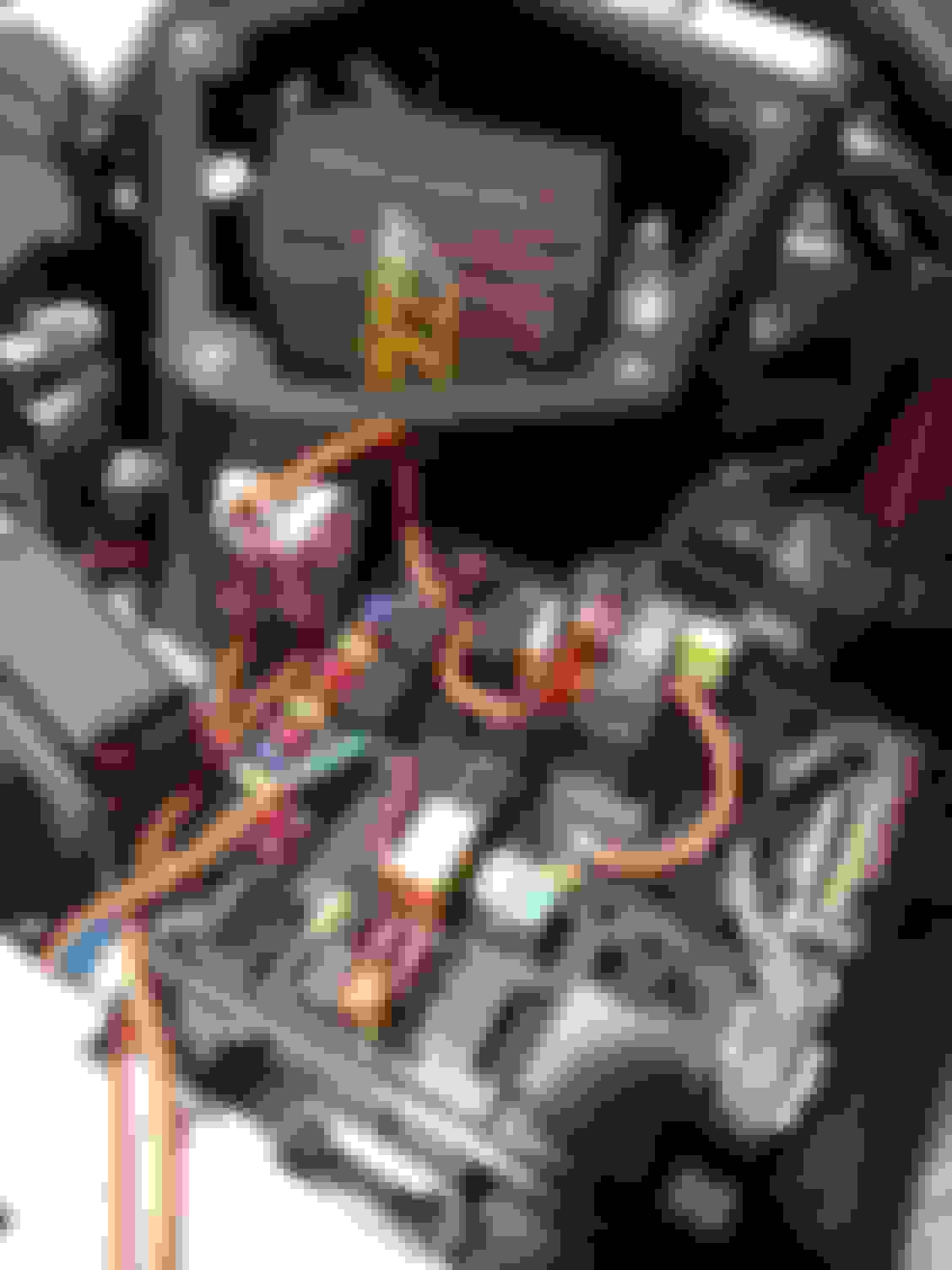
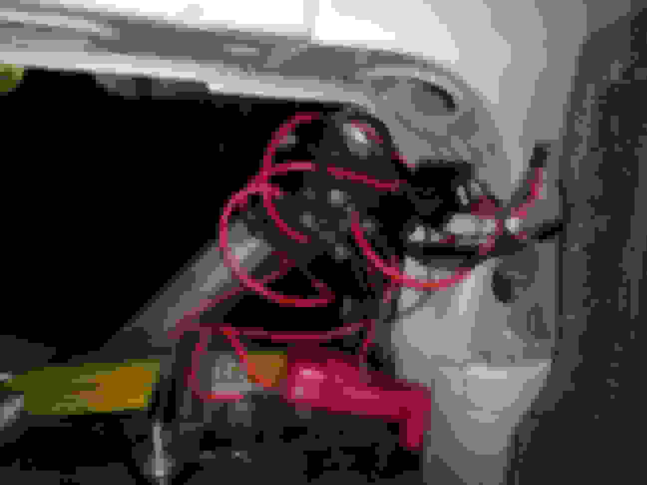
At the front of the car, I removed the fuel pump relay A-27x. I soldered the OEM relay pins 1 and 2 to quality wire that controls an SSR (input side) with the ign(+) being sent to the rear of the car (control side). This means that your in-tank pump will be locked to 9v only. I wanted this because I have a 255 in the tank and it meets my flow needs at 9v. If you run a pump at higher voltages than needed it just heats the fuel (both electrically, mechanically, and by conduction). Shown is a crappy grey SSR. Don't do that. Use Crydom relays only. For the front engine compartment the model is the Crydom D1D07.
Removed fuel pump relay and tap those pins to control a solid state relay
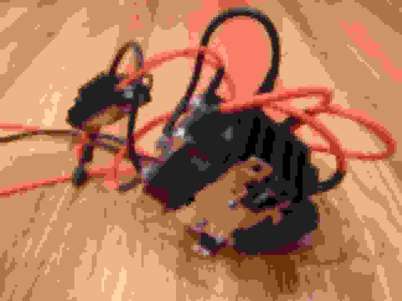
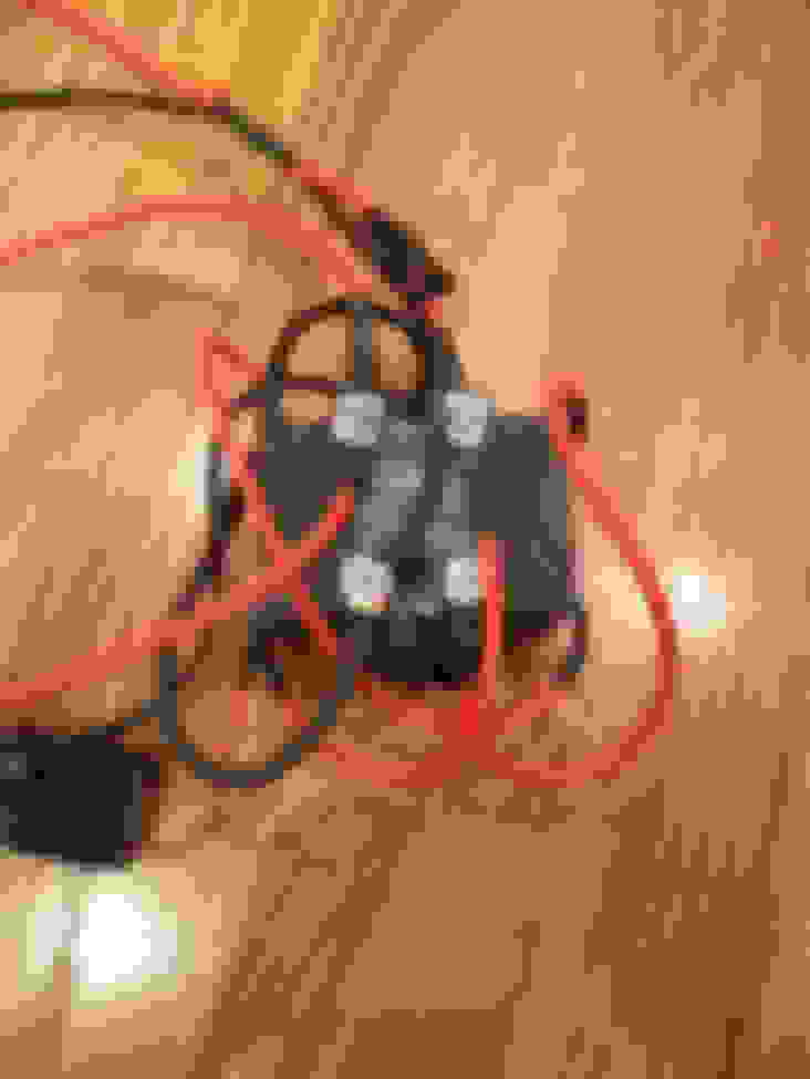
You can see I pop riveted the diode with thermal tape to the chassis after it seemed to get a bit hot after a long drive (when it was just floating in air). By using the CAR as a heat-sink it never was able to get warm again. The datasheet actually details that it CAN run quite hot without a problem, so this was overly cautious. Same goes for the 30mm fan mounted on the Castle Creations power supply. That thing NEVER gets even a bit warm. It is rated for 20amps, and is only powering the DW350il at 8.5v so it really isn't dishing out much current at all. You can probably skip the fan.
A few things to mention:
1.) The fuse and wiring must be sized for the maximum current draw of the pump. For the DW350il it is a 25amp fuse.
2.) The LOW voltage for the pump must be selected in the Castle Creations BEC to be .5 volts HIGHER than you want to run the pump at. This is due to the voltage drop across the diode. The DW350il can be run as low as 8 volts. I picked 9 volts in the CC BEC and the resulting voltage is 8.5 at the pump when it is in low voltage mode. This extends the life of the pump, and reduces heat into the fuel.
Here is a design for a SINGLE large pump mounted in the tank. This design has some assumptions:
1.) Voltage of 8.5v is correct (not too low) for the large pump you have installed. This is the stock low voltage minus diode voltage drop.
2.) 25 amp fuse and associated pink marked wire must be sized for your pump. Max: 40 amps based on solid state relay limit.
3.) The pump you have installed when run at 8.5v will not draw more than the OEM current limit. This should be fine. OEM fuse for this circuit is 10amps. What pump pulls 10 amps @8.5v ?
This setup with ONE big pump in the tank, requires a lot less parts.
Thanks for putting this together! Would you mind explaining further how the front D1D07 is working compared to the factory relay setup? I follow what you did and what it achieved but not how it differs from just having the OE relay in place. Also, do you think there's room on the underside of the fuse/relay cover to mount that Crydom?
Thanks for putting this together! Would you mind explaining further how the front D1D07 is working compared to the factory relay setup? I follow what you did and what it achieved but not how it differs from just having the OE relay in place. Also, do you think there's room on the underside of the fuse/relay cover to mount that Crydom?
The fuel pump relay is designed to power a very small coil to engage a contact. While you could run that wire to the rear of the car, and make the ecu pull that to ground, I am worried that an accidental short in routing or long term issue could cause that to be a short and hurt the ECU. To protect the ECU I had the pins 1 and 2 of the relay (coil side) simply go to the input side of the SSR. This way the SSR control side is the one pushing the high signal to the rear of the car, thus protecting the ECU from any accidental damage. The SSR on the input side is in simple terms... gentle. It is current limited and with no moving parts doesn't have any "bounce" issues or "kickback". So the D1D07 in the front has the input side connected to where the fuel relay USED TO BE, and as shown it is pins 1 + 2 which is what would have been the control coil side of the relay. I did this by wrecking a relay (hey, don't need it anymore anyhow) and therefore using the as-designed pins that go into the actual relay socket. Simply solder two wires to the two copper slots that would have gone into the socket. I started to pull the entire fuse relay box out and realized that it was going to be murder and near impossible to get to the underneath. I was going to cut and tap into the actual wires from below. So for the control side just connect the (+) to an ignition source of power (you can see I used a fuse-adder), and the other control connection goes to the rear of the car as shown in the diagram and video. Your not going to fit the SSR under the lid of the fuse box. I cut notches out in the corners so the lid still goes on fine to provide protection. Does that answer your question?
However, after installing a surge tank in my friends EvoX, we found it still had starvation issues (could see AFR's go lean, car wasn't cutting out anymore) in more extreme scenario's on track. This was resolved by running the in tank pump at full power full time, and cutting holes in the pump hanger to allow more fuel into it.
However, after installing a surge tank in my friends EvoX, we found it still had starvation issues (could see AFR's go lean, car wasn't cutting out anymore) in more extreme scenario's on track. This was resolved by running the in tank pump at full power full time, and cutting holes in the pump hanger to allow more fuel into it.
hah! And you thought I was nuts when I installed the radium hanger in addition to my surge. Which btw totally solved all fueling issues on track for me.
hah! And you thought I was nuts when I installed the radium hanger in addition to my surge. Which btw totally solved all fueling issues on track for me.
I wanted to run the in tank pump hardwired when we first did the install, but he didn't think he needed it. So when it was still an issue, we hardwired it, and English Racing gave us some pointers to cut up the hanger to allow fuel to flow into more easily. Problem solved
The radium hanger is def nice though. But we got it handled by just mangling the stock one...
Indeed, I chose the nuclear option because I just didn�t want to deal with it anymore. Haha.
fyi, my in-tank 255 is still on the oem mixed voltage.
I also am running the radium hanger, and a 255 in place of the stock jobber. I think I am OK.
But for those EXTREME setups you describe you can run the in-tank lift pump in series (electrically) with the BIG surge pump in the drawing, as long as the fuse and the wiring supports the current.
So then the in-tank lift pump AND the surge pump run dual voltage controlled by the ECU! The both go from low/high voltage as defined by curve in the ecu. That would handle those extreme fuel situations, and not have ANY pump running full voltage ALL the time. Doing that just shortens the life of the pump(s) and produces a ton of fuel heat.
When my friend still had starvation issues, the in tank pump was a walbro 255 on factory wiring, and the surge tank was hardwired walbro 450, and it has an AFPR on the fuel rail to properly regulate fuel pressure.
Now the intake pump is hardwired, and we run the surge tank on the factory wiring,but with a boost circuit like mrfred's hi/lo voltage rewire to make sure the pump has enough amps under load. That's on a hobbs switch.
The track I frequent has some high G long left turns. The track itself is like 80% left turns. My current setup is rock solid fueling wise on R-compounds with over 500whp and E78-E80 fuel. I log (including Fuel Pressure) to a SD card whenever the car is running via my RaceCapture setup. I have like 1gb worth of on-track data at this point.
Radium Surge Tank with Wally 450 HP
Torqbyte Fuel Pump controller based on MAP (programmable 2D/3D ramp table)
Radium pump hanger with Wally 255 (OEM wiring)
OEM fuel rail
OEM FPR
OEM fuel lines
SS fuel filter in-line
ID1700cc injectors
great project If you don't mind an attempt to contribute it doesn't seem like the SSRs are automotive rated. If you take a look at this doc https://www.st.com/content/ccc/resou...CD00181783.pdf (particularly pg 5/6) you can see the kinda crap that gets onto the power and signal lines in automotive. So the two approaches to dealing with this could be to harden the circuit with additional parts (examples in that linked doc) or perhaps sourcing SSR's that are automotive certified with built in protection.
If I'm wrong about the SSR's then by all means, flame on.
Your not wrong. Cars are electrical noise crazy! However, the design of using Crydom SSRs for pump control is not something that needs to be concerned with that issue. Crydom relays are top notch, and the pump is directly wired to the battery. I think the design is solid as is, and since the triggers are 3v+ there are no chances of noise causing an unwanted SSR trigger. Thanks for the input, and I certainly don't mind anyone contributing to this little project. A guy at work asked about SELLING this, and I just don't have the energy or greed to drive that...LOL... so it's open source I suppose...
Bryan,
I did look into your solution (TorqueByte) but I remember thinking it was costly by the time you added all the pieces from the website required. I also remember this was your second attempt at a controller for the surge tank pump (first one was cheaper I remember) or maybe it was a customers car that the other solution died on. I then set out to make a dead nuts reliable design that can be controlled by the factory ECU.
 Nov 3, 2018, 05:12 PM


 If you don't mind an attempt to contribute