How To: AEM Failsafe Boost and Wideband
 Apr 20, 2014, 11:53 PM
#1
Evolving Member
Thread Starter
How To: AEM Failsafe Boost and Wideband
While the basics of the install are nothing advanced, an inexperienced user may be confused by the cluster**** of wires he or she will see upon opening the box, so I figured I would write up a little How-To on the install of the gauge.
- Parts Required
AEM Failsafe Gauge
Vacuum T from pepboys (Vacu-Tite)
Vacuum connector from pepboys (Vacu-Tite)
Dayco (or any other brand) vacuum lines, 6 ft of 7/64" and 6 ft of 5/32".
Downpipe with an O2 bung (test pipe works to but DP is the best spot)
270 ohm resistor
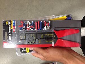
- Things I used that are not required but HIGHLY recommended for a clean install
Terminal kit from home Depot
Wire Stripper
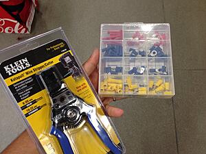
OR
Crimping tool with terminals
- Tools Required
Tactrix OP 2.0 cable
Laptop
Pliars
Wire strippers (teeth will work too)
Electric tape OR the supplied terminals
10mm wrench/socket
Jack with 2x Stands
O2 Socket tool or an adjustable wrench
Flat Head Screwdriver
Cross Head Screwdriver (is that what its called?)
- Recommended Number of People
Part 1: 1
Part 2: 1
Part 3: 2
Part 4: 1
- Difficulty
Part 1: 2/10
Part 2: 4/10
Part 3: 6/10 (primarily because of the stupid vaccum hose routing from the engine bay down into the cabin)
Part 4: 2/10
- Time to complete
~2 hours for the whole thing
Pre-install ritual (do this before any install!)
1. Pull pants down
2. Look back and check to see if you have hands growing out of your ***. If not, proceed with the install.
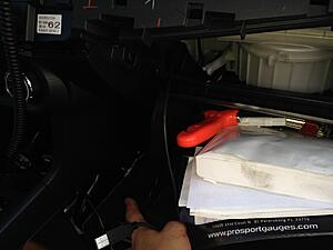
Everything it comes with:
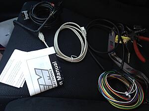
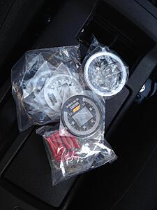
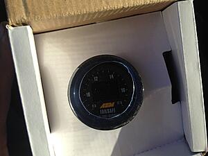
We will NOT need the white USB extension, the hold down bracket (assuming you are using an AutoMeter gauge cup as I am), and the supplied vacuum and T-fitting as they useless (due to being short (vacuum) and thin as **** (T))
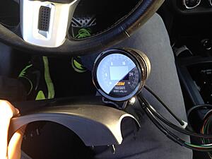
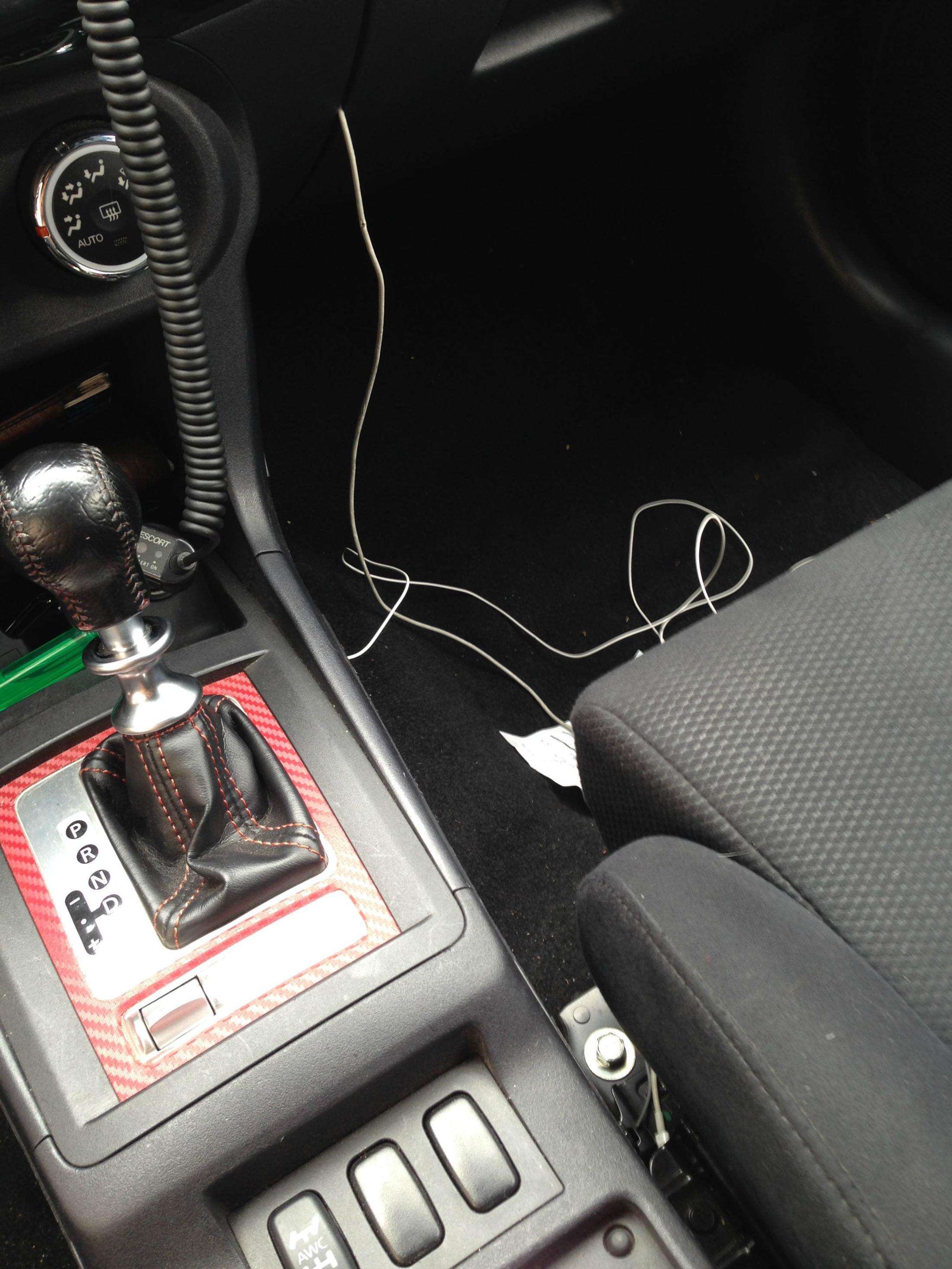
Before the entire thing starts, place the gauge wherever you want it to be and route the wires to an accessible place where you can work with them. I put my gauge on the steering column cover:
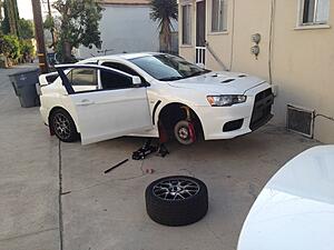
Also, go ahead and jack your car up now so you don't have to worry about it later:
Part 1: Primary wiring
AEM is a confusing company, as they send a lot of what you don't need a lot of and not enough of what you actually need a lot of. They sent a spaghetti of wires that I will now help you organize through.
The kit comes with two harnesses, one going to the Bosch O2 sensor and the other responsible for power and other good stuff. For now, pick up the harness responsible for powering the unit (the one without anything at the end but wires). This is what you will be looking at:
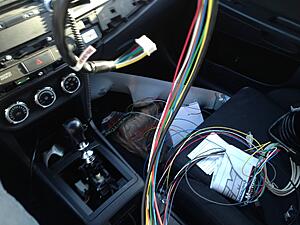
Good news, you only need TWO wires from all that and here's a quick look-over at what each wire does:
Red- Power wire, basically this feeds power to the gauge
Black- Ground wire, connect to a ground source (will show in a bit)
Gray- Connects to the dash light fuse to dim the display. We will NOT be using this because our car's dash is always ON, meaning the display will always be dimmed. You could connect this to the headlight switch instead (in theory) but I have not yet tested this.
Blue - Does the failsafe Voodo. TJ (UT_EvoX) has a write up on how it works exactly,click here to view. You could hook this up while working the wiring as well.
Yellow: - From my understanding this is used to log boost but we will not be needing this as our car reads boost pressure values through the ECU.
White- This will be hooked up to the rear O2 sensor in order to log AFR.
Brown- Ground this wire separately from the Black wire
Green- Connects to the tach gauge of most cars for logging purposes, I have yet to figure out how to hook it up to the tach.
USB wire - Used to configure the failsafe gauge, this will be routed into the glove box.
For the first part, we will need the Red, Black, Brown and White wires. Once I figure out how, I will update the OP on how to hook up the [COLOR="gray "]gray [/green green wire. Click here to find out how to hook up the blue wire.
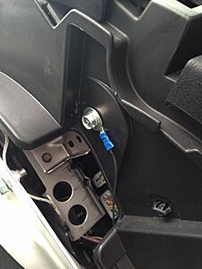
Let us work with the ground wire first. It will be hooked up in the following area:
Simply pull the covering plastic off and you will see the bolt. This bolt will be our ground. If you bought the terminal kit, fit a terminal over the ground wire (Black) after you have trimmed it to appropriate length. It should look something like this:
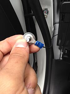
If you don't have a terminal you could just ghetto wrap the wire around the bolt:
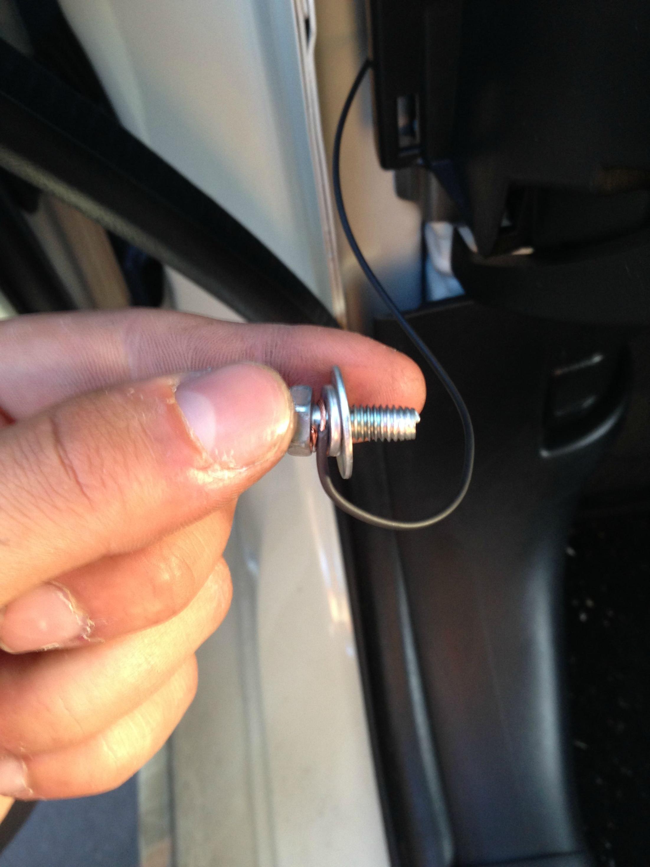
Put the bolt back in- ground is now set-up.
Now we will work with the Red wire. You will need to access the fuse box located on the driver's side of the car. Open up the door to the fuse box and remove the accessory fuse shown in the pictures (Fuse blue 15, red wire coming out of it)
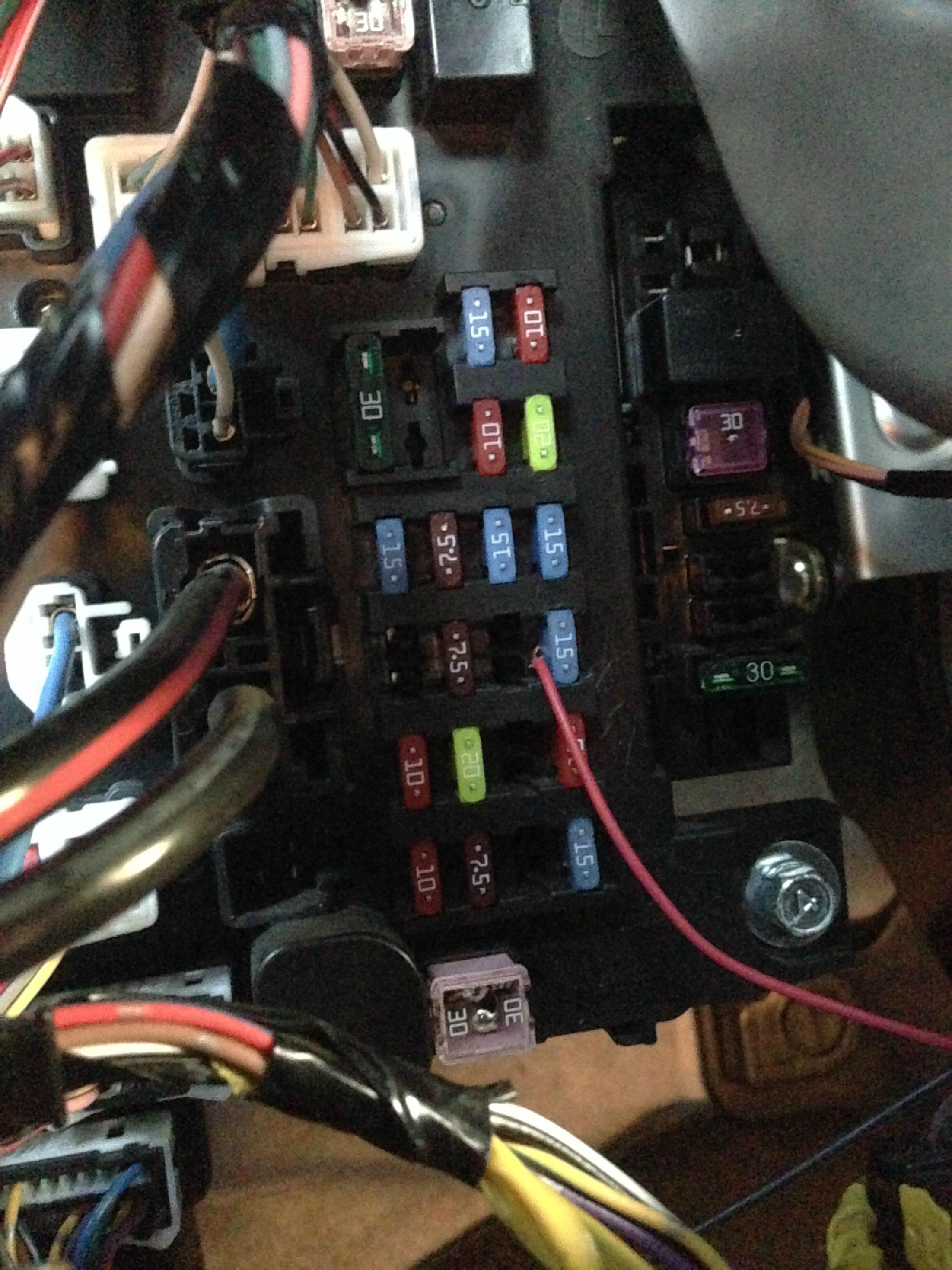
Wrap the red wire around it and put the fuse back
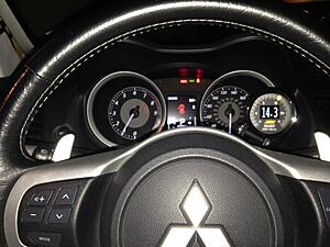
Now we will test the gauge and see if it powers on, so simply turn the ignition on.
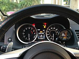
The above message basically means your sensor is not connected, which is fine assuming your sensor is in fact not connected. The gauge powers on and works great, now on to the USB wire. This will be led across the car into the glove box. My car is SST so this may be a bit more/less complicated for folks with 5MT.
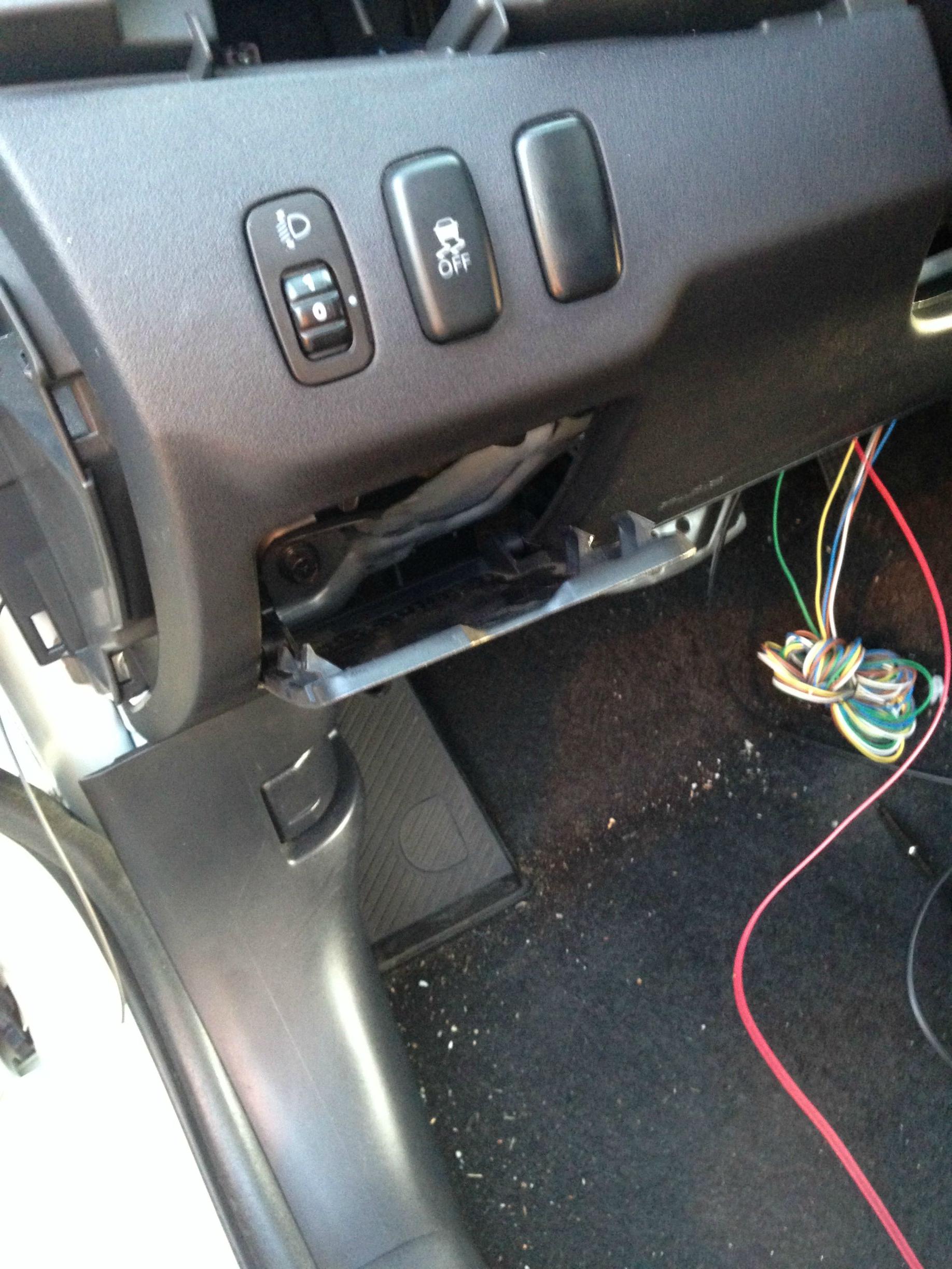
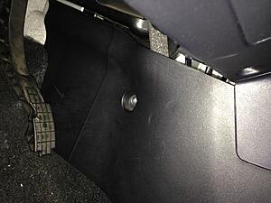
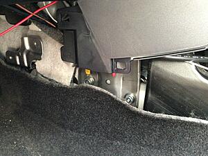
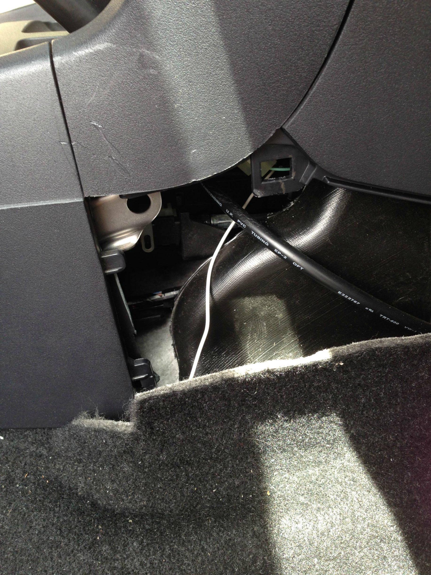
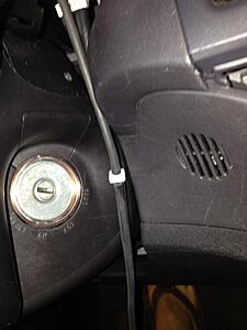
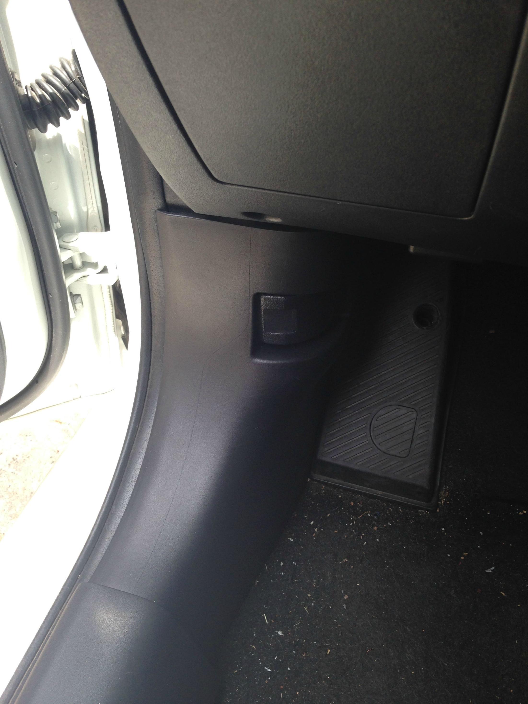
Remove the plastic piece next to the gas pedal. It is held by a screwdriver, loosen that and yank it out. Don't be afraid to pull hard, you may break a few clips but it will go back in:
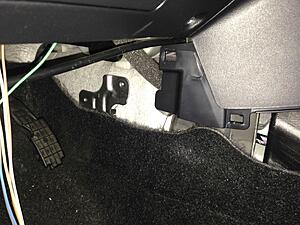
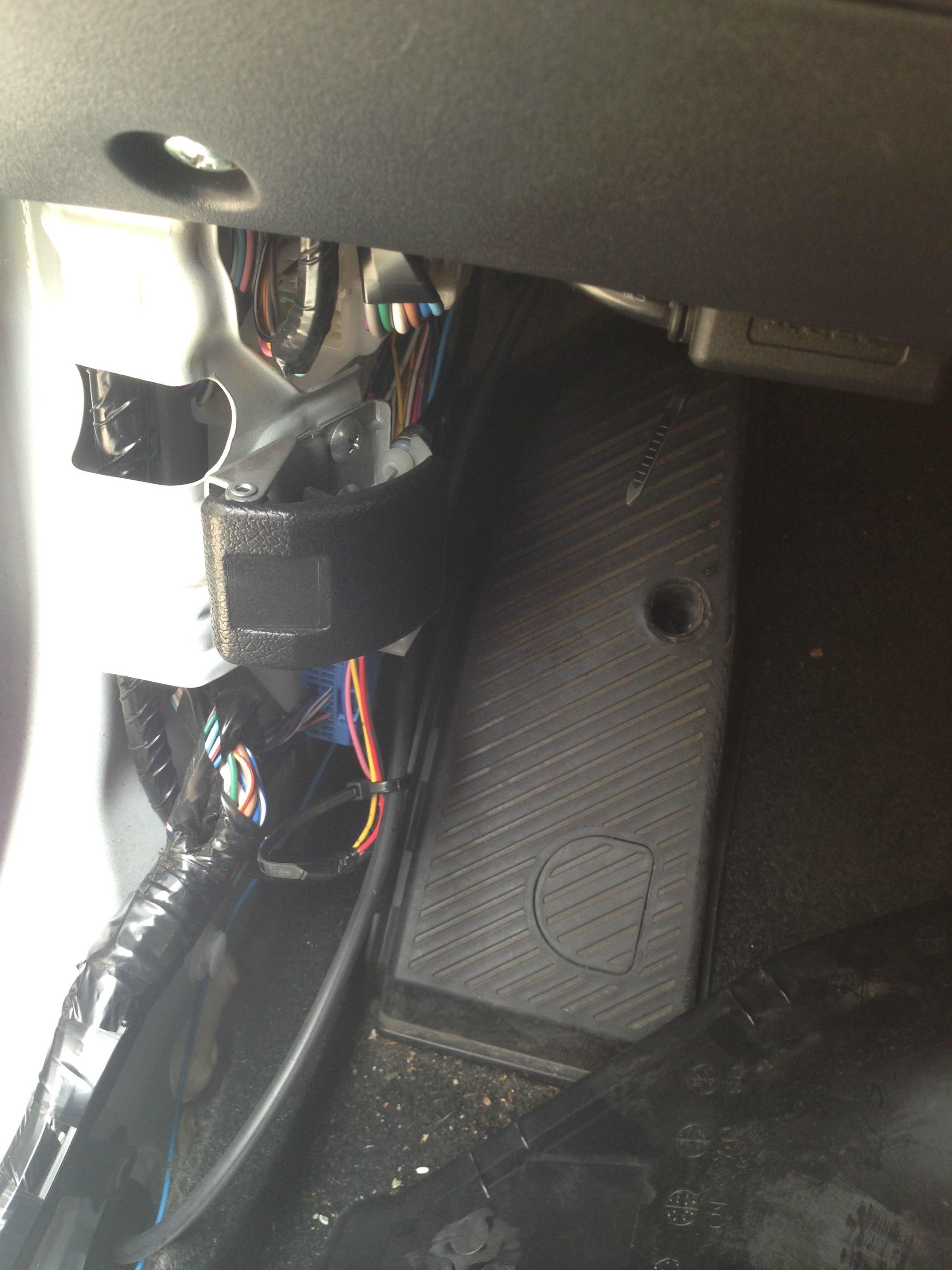
Go to the other side and do the same. Come back to the driver's side and look across and you should be able to see the other side.
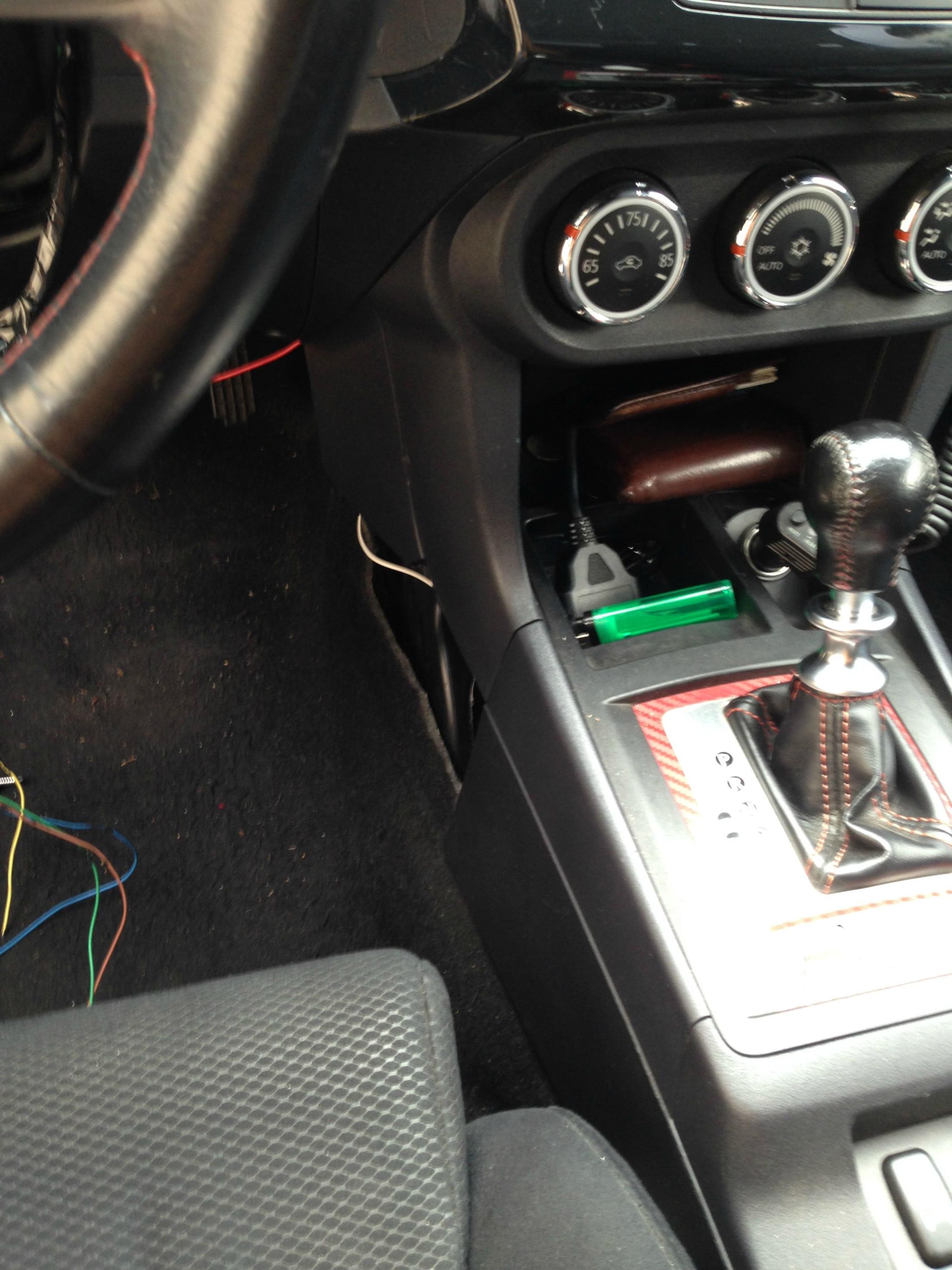
Route your USB cable through here and pull it up into your glove box (this will require removal of the glove box).
With the USB cable in an accessible spot you will be able to work on your failsafe whenever you prefer and the wire will not be getting in your way on day-to-day basis.
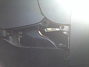
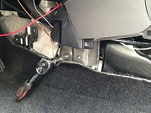
Move ahead with the Brown wire. Ground it on the leftmost bolt behind the carpet shown in the picture below (socket over it).
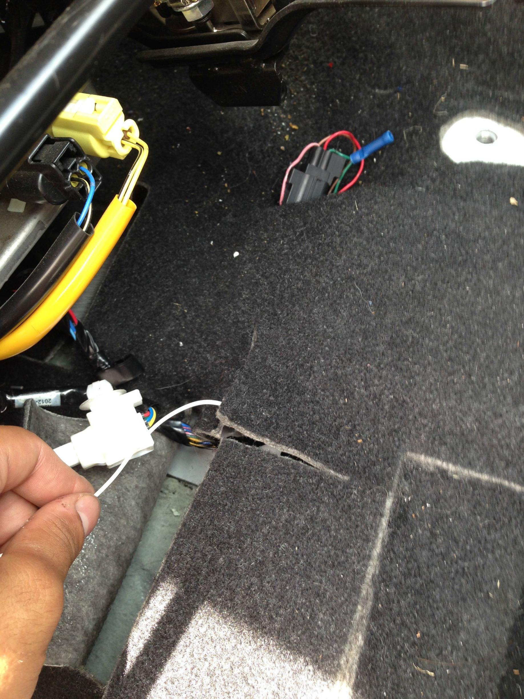
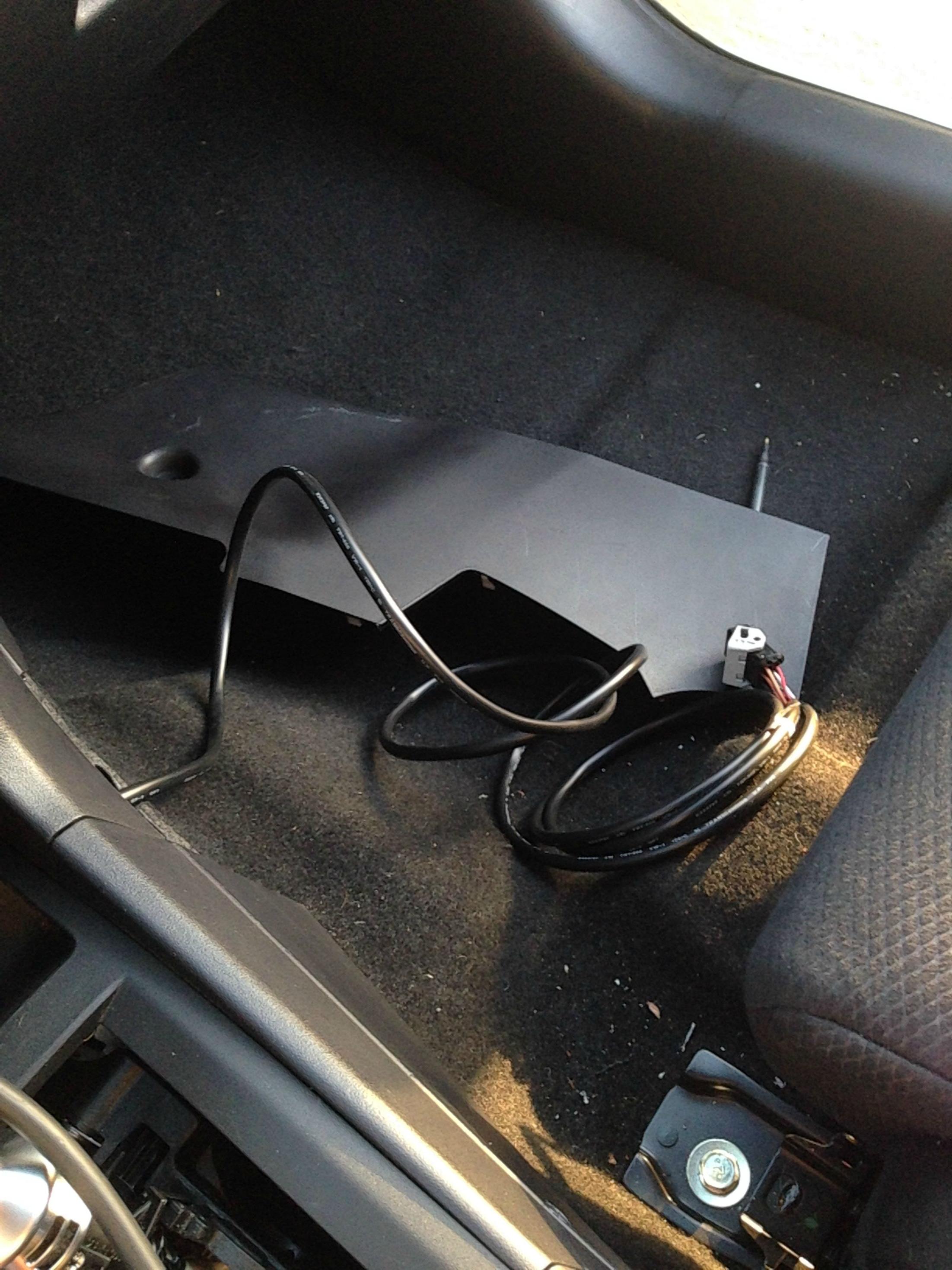
Once you have the brown wire grounded, move on to the White wire. OPTIONAL This wire will be used in order to log AFR through the ECU. Route the wire the same way you routed the USB cable, except instead of pulling it up into the glove box, route it down into the carpet.
For this wire, it will be easier to unbolt the seat and move it as far back as possible.
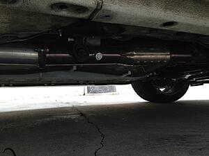
Remove the rear O2 sensor and plug the hole on your test pipe/cat with an o2 sensor plug. You can grab one of these from your local muffler shop.
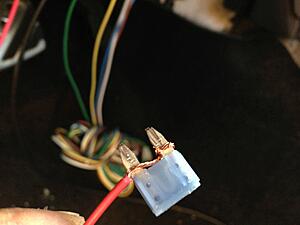
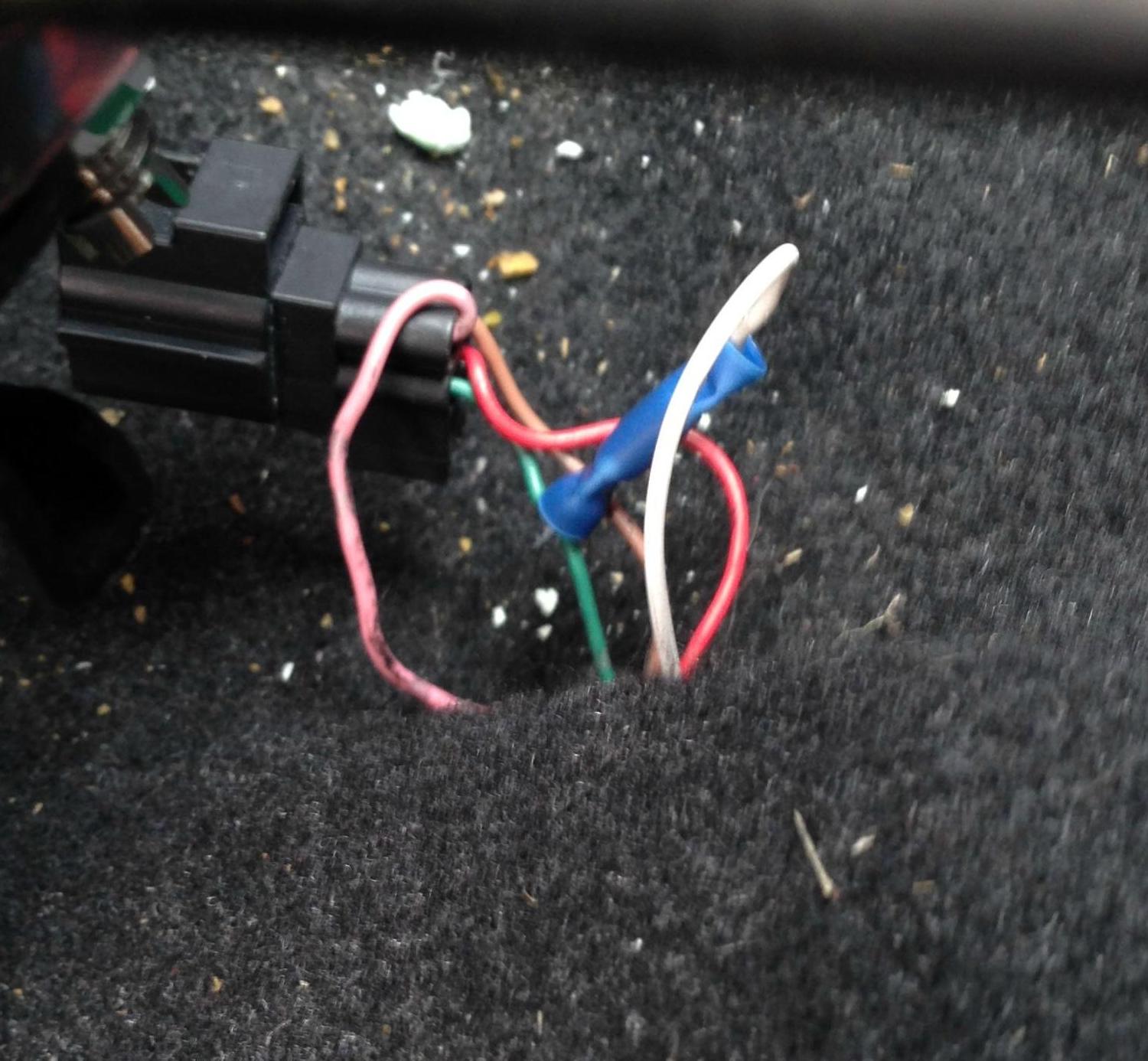
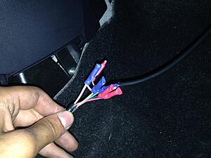
Once the sensor is removed, pull up the clip that's coming out of the wiring harness.Do not be afraid to make incisions in the carpeting to access it. Once the clip is visible, cut the green wire (2013 and up) or yellow wire (2008-2012). You will now have two green/yellow wires- twist the wires together then put them through one end of a terminal. Leave the other end open. Crimp the lower end where the wires are put through.
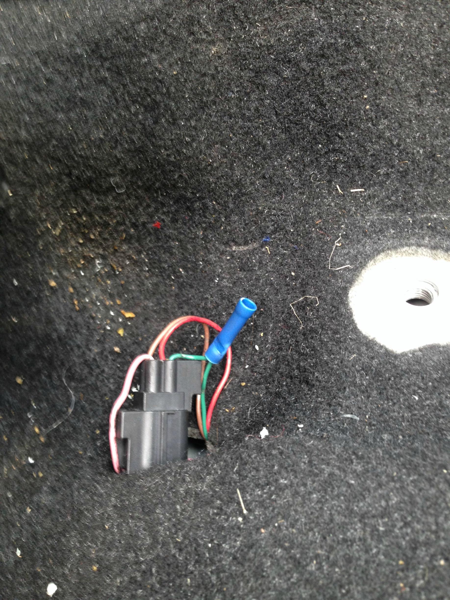
Route the white wire from underneath the carpeting and place it on the other end of the terminal. Crimp the terminal.
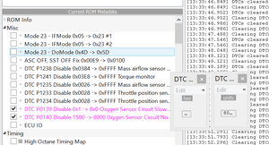
Now grab your laptop and your tactrix cable. Pull up your ROM and make the following changes:
Change the purple values from 0x1 to 0x0 for 0139, and 1500 to 8000 for 0140 (as seen below).
Scroll down and find Ecu Options set 2. Change bit1 value from 1 to 0 by clicking "[" button
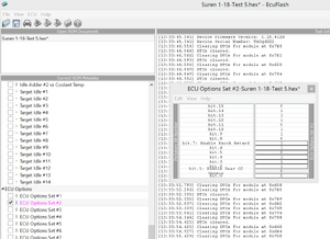
Write the ROM onto your ECU. Now, pull up EvoScan and create a new data list on the very bottom. Enter the following for RAX:
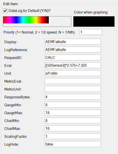
The formula for Mode23 Users is as follows: AFR = (x * 2.375) + 7.3125
On to the next part
Part 2: Air-Fuel Configuration
We will now need the second harness with a clip at the end. This will be routed from the gauge, across the car to the passenger side. Follow the same instructions as with the USB cable to get it across (but don't lead it into the glove box).
Remove the carpet on the passenger side, the cloth underneath the carpet and the Styrofoam piece underneath the cloth. You will see a gray wire going through a grommet as such:
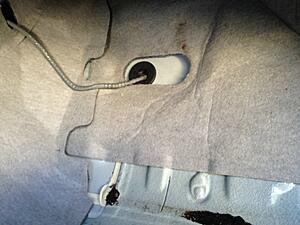
Remove the grommet, cut a hole in it and lead the wire down. Grab your O2 sensor
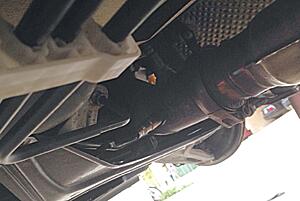
The wire will now be hanging under the car, pull on it (there's more than enough of wire there). Before connecting the wire to the O2 sensor, install the O2 sensor in the bung as that will prevent the wire from being twisted. Hook up the wire and this is relatively what it should look like:
Put the Styrofoam, cloth and carpet back on and you have AFR available.
Optional:
Grab a few terminals and shorten up the harness, to do this just cut the the wires and match the like colors to each other. You could also twist them together and wrap them in electrical tape or solder them together and wrap them in electrical tape. I personally twisted them together and put terminals over them as that makes it look nice and clean:
...sort of.
Put everything together on the passenger side and start the car to see if you get a reading:
Now you can set the car down from the stands.
Part 3: Boost
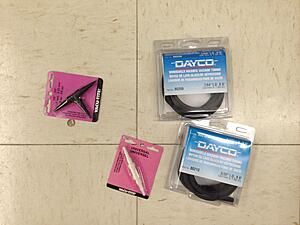
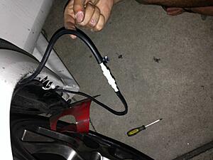
This is the most difficult part of the install just because of routing the vacuum hose through the fender. My good friend (and a member of the forums) Ara came by and helped me out with the install. You will need a vacuum T from pepboys (or any other automotive store selling these) along with a vacuum connector that is also a vacuum adapter + vacuum lines (sizes and lengths listed in the beginning of the how to) as seen in the picture below:
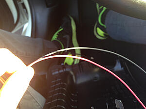
Once you get the vacuum lines, grab the 7/64 one and hook it up to the vacuum line coming out of the gauge.
Now before anything is done to this line, remove the plastic pieces under the center console:
Lead the vacuum hose into the grommet slightly above the trunk and gas cap levers
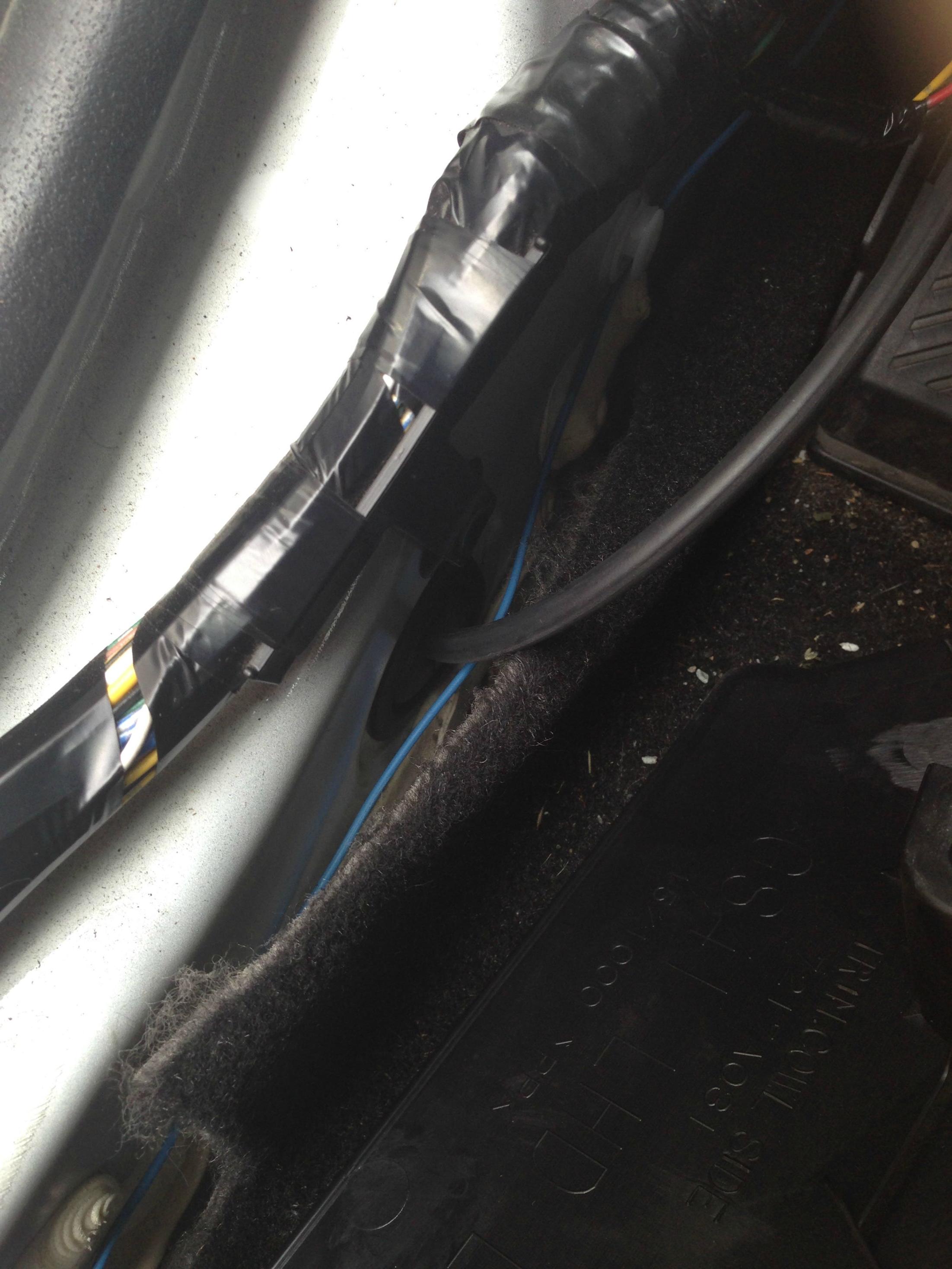
Have your friend pull the vacuum line from the other side. This may take a few tries.
Loosely zip-tie the vacuum line to the surrounding wires:
Now pop the hood and find the vacuum line going into the BOV from the manifold:
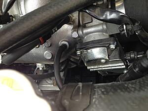
Tap into it with your T and route the third vacuum line (5/32") down the fender. Once the two lines are together, join them using the universal vacuum line fitting adapter joiner whatever the **** it is, it should look like this:
Trim up the hoses and place them inside the fender wall.
Now before testing the boost gauge you must set- up the failsafe to read boost.
Part 4: Minor set-up
This does NOT set up the failsafe, that will be done by your tuner (or yourself assuming you are experienced enough for that, which I am not).
My gauge is set up in such a way so the center display shows AFR while the color changing LED's show boost. In order to do this you will have to download the AEM failsafe software found in the link below:
http://www.aemelectronics.com/catalo...-downloads-72/
Download WF Config Software and install it on your computer.
Once open you will see the following:
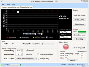
Click on "Gauge Configuration".
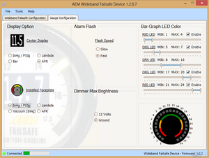
Here you could set your gauge up whichever way you want. Mine is set up so the center display is AFR and the LEDs are boost. Since it's a bit difficult to read boost through LEDs, I also changed up the color scheme of LEDs:
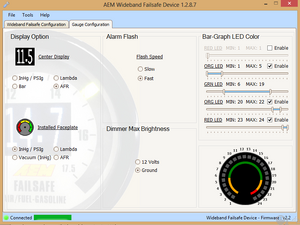
That way once the gauge LEDs are Yellow (on the right side) my boost is between 26-28 psi, which is what I'm tuned for. Red is overboost and green is from 0-25 psi. Yellow on the left side is vacuum. The settings will be automatically saved. Now you can start the car and take it for a spin to see if the boost gauge is working properly.
I hope this helps people out and if you have any questions feel free to comment below.
- Parts Required
AEM Failsafe Gauge
Vacuum T from pepboys (Vacu-Tite)
Vacuum connector from pepboys (Vacu-Tite)
Dayco (or any other brand) vacuum lines, 6 ft of 7/64" and 6 ft of 5/32".
Downpipe with an O2 bung (test pipe works to but DP is the best spot)
270 ohm resistor
- Things I used that are not required but HIGHLY recommended for a clean install
Terminal kit from home Depot
Wire Stripper

OR
Crimping tool with terminals

- Tools Required
Tactrix OP 2.0 cable
Laptop
Pliars
Wire strippers (teeth will work too)
Electric tape OR the supplied terminals
10mm wrench/socket
Jack with 2x Stands
O2 Socket tool or an adjustable wrench
Flat Head Screwdriver
Cross Head Screwdriver (is that what its called?)
- Recommended Number of People
Part 1: 1
Part 2: 1
Part 3: 2
Part 4: 1
- Difficulty
Part 1: 2/10
Part 2: 4/10
Part 3: 6/10 (primarily because of the stupid vaccum hose routing from the engine bay down into the cabin)
Part 4: 2/10
- Time to complete
~2 hours for the whole thing
Pre-install ritual (do this before any install!)
1. Pull pants down
2. Look back and check to see if you have hands growing out of your ***. If not, proceed with the install.
Everything it comes with:


We will NOT need the white USB extension, the hold down bracket (assuming you are using an AutoMeter gauge cup as I am), and the supplied vacuum and T-fitting as they useless (due to being short (vacuum) and thin as **** (T))
Before the entire thing starts, place the gauge wherever you want it to be and route the wires to an accessible place where you can work with them. I put my gauge on the steering column cover:

Also, go ahead and jack your car up now so you don't have to worry about it later:

Part 1: Primary wiring
AEM is a confusing company, as they send a lot of what you don't need a lot of and not enough of what you actually need a lot of. They sent a spaghetti of wires that I will now help you organize through.
The kit comes with two harnesses, one going to the Bosch O2 sensor and the other responsible for power and other good stuff. For now, pick up the harness responsible for powering the unit (the one without anything at the end but wires). This is what you will be looking at:

Good news, you only need TWO wires from all that and here's a quick look-over at what each wire does:
Red- Power wire, basically this feeds power to the gauge
Black- Ground wire, connect to a ground source (will show in a bit)
Gray- Connects to the dash light fuse to dim the display. We will NOT be using this because our car's dash is always ON, meaning the display will always be dimmed. You could connect this to the headlight switch instead (in theory) but I have not yet tested this.
Blue - Does the failsafe Voodo. TJ (UT_EvoX) has a write up on how it works exactly,click here to view. You could hook this up while working the wiring as well.
Yellow: - From my understanding this is used to log boost but we will not be needing this as our car reads boost pressure values through the ECU.
White- This will be hooked up to the rear O2 sensor in order to log AFR.
Brown- Ground this wire separately from the Black wire
Green- Connects to the tach gauge of most cars for logging purposes, I have yet to figure out how to hook it up to the tach.
USB wire - Used to configure the failsafe gauge, this will be routed into the glove box.
For the first part, we will need the Red, Black, Brown and White wires. Once I figure out how, I will update the OP on how to hook up the [COLOR="gray "]gray [/green green wire. Click here to find out how to hook up the blue wire.

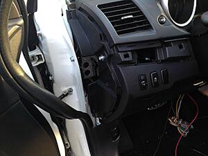
Let us work with the ground wire first. It will be hooked up in the following area:

Simply pull the covering plastic off and you will see the bolt. This bolt will be our ground. If you bought the terminal kit, fit a terminal over the ground wire (Black) after you have trimmed it to appropriate length. It should look something like this:

If you don't have a terminal you could just ghetto wrap the wire around the bolt:
Put the bolt back in- ground is now set-up.

Now we will work with the Red wire. You will need to access the fuse box located on the driver's side of the car. Open up the door to the fuse box and remove the accessory fuse shown in the pictures (Fuse blue 15, red wire coming out of it)
Wrap the red wire around it and put the fuse back

Now we will test the gauge and see if it powers on, so simply turn the ignition on.

The above message basically means your sensor is not connected, which is fine assuming your sensor is in fact not connected. The gauge powers on and works great, now on to the USB wire. This will be led across the car into the glove box. My car is SST so this may be a bit more/less complicated for folks with 5MT.
Remove the plastic piece next to the gas pedal. It is held by a screwdriver, loosen that and yank it out. Don't be afraid to pull hard, you may break a few clips but it will go back in:


Go to the other side and do the same. Come back to the driver's side and look across and you should be able to see the other side.

Route your USB cable through here and pull it up into your glove box (this will require removal of the glove box).

With the USB cable in an accessible spot you will be able to work on your failsafe whenever you prefer and the wire will not be getting in your way on day-to-day basis.
Move ahead with the Brown wire. Ground it on the leftmost bolt behind the carpet shown in the picture below (socket over it).


Once you have the brown wire grounded, move on to the White wire. OPTIONAL This wire will be used in order to log AFR through the ECU. Route the wire the same way you routed the USB cable, except instead of pulling it up into the glove box, route it down into the carpet.
For this wire, it will be easier to unbolt the seat and move it as far back as possible.
Remove the rear O2 sensor and plug the hole on your test pipe/cat with an o2 sensor plug. You can grab one of these from your local muffler shop.

Once the sensor is removed, pull up the clip that's coming out of the wiring harness.Do not be afraid to make incisions in the carpeting to access it. Once the clip is visible, cut the green wire (2013 and up) or yellow wire (2008-2012). You will now have two green/yellow wires- twist the wires together then put them through one end of a terminal. Leave the other end open. Crimp the lower end where the wires are put through.
Route the white wire from underneath the carpeting and place it on the other end of the terminal. Crimp the terminal.
Now grab your laptop and your tactrix cable. Pull up your ROM and make the following changes:
Change the purple values from 0x1 to 0x0 for 0139, and 1500 to 8000 for 0140 (as seen below).

Scroll down and find Ecu Options set 2. Change bit1 value from 1 to 0 by clicking "[" button

Write the ROM onto your ECU. Now, pull up EvoScan and create a new data list on the very bottom. Enter the following for RAX:

The formula for Mode23 Users is as follows: AFR = (x * 2.375) + 7.3125
On to the next part
Part 2: Air-Fuel Configuration
We will now need the second harness with a clip at the end. This will be routed from the gauge, across the car to the passenger side. Follow the same instructions as with the USB cable to get it across (but don't lead it into the glove box).
Remove the carpet on the passenger side, the cloth underneath the carpet and the Styrofoam piece underneath the cloth. You will see a gray wire going through a grommet as such:

Remove the grommet, cut a hole in it and lead the wire down. Grab your O2 sensor
The wire will now be hanging under the car, pull on it (there's more than enough of wire there). Before connecting the wire to the O2 sensor, install the O2 sensor in the bung as that will prevent the wire from being twisted. Hook up the wire and this is relatively what it should look like:

Put the Styrofoam, cloth and carpet back on and you have AFR available.
Optional:
Grab a few terminals and shorten up the harness, to do this just cut the the wires and match the like colors to each other. You could also twist them together and wrap them in electrical tape or solder them together and wrap them in electrical tape. I personally twisted them together and put terminals over them as that makes it look nice and clean:

...sort of.
Put everything together on the passenger side and start the car to see if you get a reading:

Now you can set the car down from the stands.
Part 3: Boost
This is the most difficult part of the install just because of routing the vacuum hose through the fender. My good friend (and a member of the forums) Ara came by and helped me out with the install. You will need a vacuum T from pepboys (or any other automotive store selling these) along with a vacuum connector that is also a vacuum adapter + vacuum lines (sizes and lengths listed in the beginning of the how to) as seen in the picture below:

Once you get the vacuum lines, grab the 7/64 one and hook it up to the vacuum line coming out of the gauge.

Now before anything is done to this line, remove the plastic pieces under the center console:
Lead the vacuum hose into the grommet slightly above the trunk and gas cap levers
Have your friend pull the vacuum line from the other side. This may take a few tries.
Loosely zip-tie the vacuum line to the surrounding wires:
Now pop the hood and find the vacuum line going into the BOV from the manifold:

Tap into it with your T and route the third vacuum line (5/32") down the fender. Once the two lines are together, join them using the universal vacuum line fitting adapter joiner whatever the **** it is, it should look like this:

Trim up the hoses and place them inside the fender wall.
Now before testing the boost gauge you must set- up the failsafe to read boost.
Part 4: Minor set-up
This does NOT set up the failsafe, that will be done by your tuner (or yourself assuming you are experienced enough for that, which I am not).
My gauge is set up in such a way so the center display shows AFR while the color changing LED's show boost. In order to do this you will have to download the AEM failsafe software found in the link below:
http://www.aemelectronics.com/catalo...-downloads-72/
Download WF Config Software and install it on your computer.
Once open you will see the following:

Click on "Gauge Configuration".

Here you could set your gauge up whichever way you want. Mine is set up so the center display is AFR and the LEDs are boost. Since it's a bit difficult to read boost through LEDs, I also changed up the color scheme of LEDs:

That way once the gauge LEDs are Yellow (on the right side) my boost is between 26-28 psi, which is what I'm tuned for. Red is overboost and green is from 0-25 psi. Yellow on the left side is vacuum. The settings will be automatically saved. Now you can start the car and take it for a spin to see if the boost gauge is working properly.
I hope this helps people out and if you have any questions feel free to comment below.
Last edited by mrwickd123; Sep 13, 2014 at 11:35 AM.

The following users liked this post:
MV auto (Feb 13, 2019)

 Apr 23, 2014, 09:14 AM
#4
Evolving Member
Thread Starter
At the moment I didn't have one but I completely agree, makes things tons easier too. Good point, I'll add it once I'm in front of a PC
Jul 19, 2014, 03:39 PM
#5
Evolving Member
Thread Starter
OP has been updated.
Added:
-Grounding the brown wire
-Connecting the white wire (optional)
-EcuFlash settings
-Evoscan settings and failsafe formula.
Added:
-Grounding the brown wire
-Connecting the white wire (optional)
-EcuFlash settings
-Evoscan settings and failsafe formula.

Trending Topics
Jul 23, 2014, 08:51 PM
#8
Why did you use 2 different size vacuum hoses? If I can get a long enough hose, can I not just go straight from the hose at the back of the gauge and all the way to the T fitting I created from the intake manifold? Doing so also eliminate the need of that universal adapter or joiner as you called it?
 Nov 5, 2014, 12:23 PM
#11
Newbie

Join Date: Aug 2012
Location: Colorado
Posts: 17
Likes: 0
Received 0 Likes
on
0 Posts
Great writeup, I will have to modify my install with a few of these things.
Have any of you, with this gauge, had trouble with it not coming on when you start the car? I may have just powered the gauge from the wrong fuse, but occasionally it stays dark after starting the car.
I've not seen it stay dark just from turning on the accessory power, however.
Have any of you, with this gauge, had trouble with it not coming on when you start the car? I may have just powered the gauge from the wrong fuse, but occasionally it stays dark after starting the car.
I've not seen it stay dark just from turning on the accessory power, however.
 Nov 17, 2014, 09:41 AM
#13
Newbie

Join Date: Oct 2013
Location: Richmond, BC, Canada
Posts: 8
Likes: 0
Received 0 Likes
on
0 Posts
I too have had similar issues as Roflberry has had. I chalk it up to gremlins since I can't quite figure out what the issue is.
I have double checked all the wires and followed as per the DIY.
I have double checked all the wires and followed as per the DIY.

