When you click on links to various merchants on this site and make a purchase, this can result in this site earning a commission. Affiliate programs and affiliations include, but are not limited to, the eBay Partner Network.
2017 Mitsubishi Outlander Sport After Market Tail Light Resistor Ohms/Volts Required
Hey everyone!
I recently installed the Black Smoked LED Tail Lights on my 2017 Outlander Sport, but of course I'm getting the ASC Service Required light and notification. I know this is a known issue as it require resistors, but I can't seem to find anywhere online what resist type (ohm/voltage combination) and the past 2 attempts I have done seem to not be correct (light turns on after 10 minutes of driving roughly).
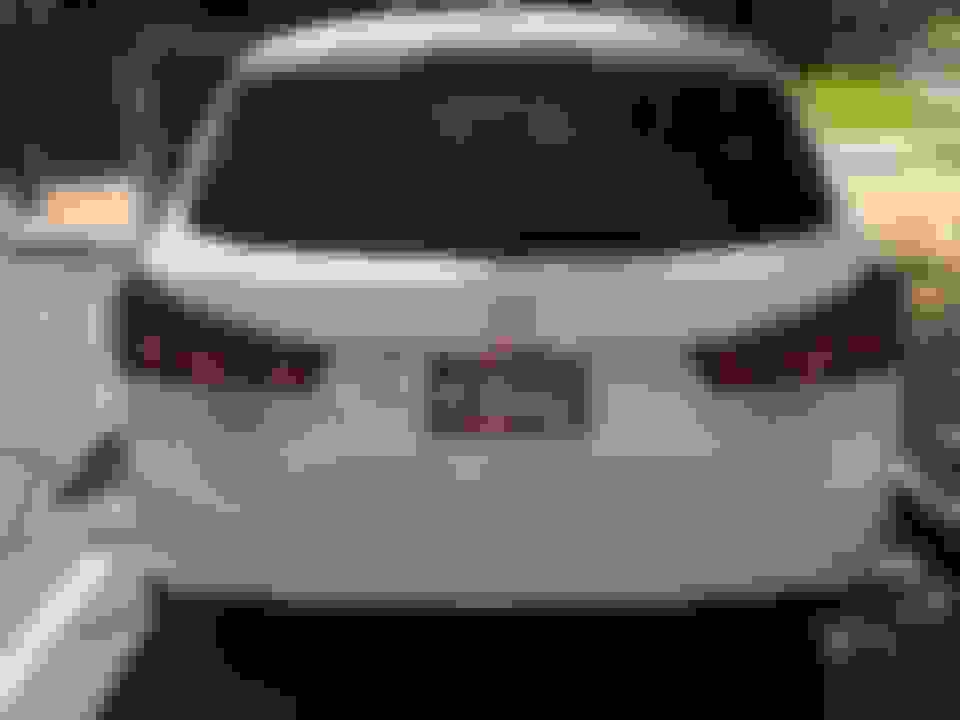
Can someone please help me out? I don't really have the stock lights in a easy to access place to check, and everywhere online says mixed results (100ohms, 1000ohms, 180ohms..). For reference on which exact lights, please see the image attached. Thank you all so much!!!
PS: Yes, that's my real license plate. If your in Arizona and see me/it, say hi!
I recently installed the Black Smoked LED Tail Lights on my 2017 Outlander Sport, but of course I'm getting the ASC Service Required light and notification. I know this is a known issue as it require resistors, but I can't seem to find anywhere online what resist type (ohm/voltage combination) and the past 2 attempts I have done seem to not be correct (light turns on after 10 minutes of driving roughly).
Can someone please help me out? I don't really have the stock lights in a easy to access place to check, and everywhere online says mixed results (100ohms, 1000ohms, 180ohms..). For reference on which exact lights, please see the image attached. Thank you all so much!!!
PS: Yes, that's my real license plate. If your in Arizona and see me/it, say hi!
Hey did you ever find out how to get your led tail lights to proper work and turn the ASC off?
No. 1000ohms does not work, I tried 150ohms and did not work either, I forget what else I tried but I have two 25ohm (50ohm total overall) and same light. I kinda just gave up. I have yet to try 2 50ohms or 2 100ohms, but don�t really feel like wasting more money trying to experiment. I asked everyone and either they don�t know or they label it as a �standard ohm� (whatever that means).
For anyone still looking for the resistor combo I am in contact with a shop that has the right combo and these instructions. All credit goes to these guys: https://www.nhk-usa.com/ I'm gonna buy the kit and try it out and update once they're installed.
So after I installed a 50w 6ohm resistor on the light like is shows the error went away and everything is working like normal again. So if anyone is still having issues just install it like it shows above and it will fix the issue.
This is a poor solution. Why not use the highest resistance possible that will pull the needed current draw to satisfy the software on the module? You can probably use a much higher resistance therefore stressing the drivers on the computer a lot less (which will prevent it from failing sooner)
This is a poor solution. Why not use the highest resistance possible that will pull the needed current draw to satisfy the software on the module? You can probably use a much higher resistance therefore stressing the drivers on the computer a lot less (which will prevent it from failing sooner)
No one knows what that exact number is. Several combos have been tried to no avail. You are more than welcome to help find the exact number needed. That being said going from LED to LED I doubt the difference is exponential but I'm by no means an electrician lol
This is a poor solution. Why not use the highest resistance possible that will pull the needed current draw to satisfy the software on the module? You can probably use a much higher resistance therefore stressing the drivers on the computer a lot less (which will prevent it from failing sooner)
Not to be nitpicky but software code is not mechanical. Having a resistor or not having a resistor doesn't put "stress" on the computer. The computer only reads values and when a value is above or below a specified range it returns a "error" which can be either a warning light, deactivation or activation of systems or a combination of all 3. Canbus errors might trigger "limp home" modes or reduced power modes but that is strictly a function of software, nothing mechanical about it. Now running your vehicle extensively with Canbus errors might reduce the longevity of your vehicle due to mechanical stress, but not it's computer ecu. You can't wear out computer code.
A simple potentiometer will solve this problem for you. Start at the resistance you know works- and increase it until the problem re-appears. This is a simple empirical exercise.
A 6 ohm resistor will draw more than 2 amps at a 14v supply. I doubt your OEM bulbs draw that much.
Not to be nitpicky but software code is not mechanical. Having a resistor or not having a resistor doesn't put "stress" on the computer. The computer only reads values and when a value is above or below a specified range it returns a "error" which can be either a warning light, deactivation or activation of systems or a combination of all 3. Canbus errors might trigger "limp home" modes or reduced power modes but that is strictly a function of software, nothing mechanical about it. Now running your vehicle extensively with Canbus errors might reduce the longevity of your vehicle due to mechanical stress, but not it's computer ecu. You can't wear out computer code.
This has nothing to do with CANBUS. CANBUS is the most misunderstood and abused electrical/automotive term on the modification scene. It's so widely abused that even the vendors use it incorrectly. CANBUS has to do with digital communication across a network of modules.
Having excessive current draw will cause load on a driver. The circuit is controlled by a transistor that turns on and off by the base turn on signal coming from a chip. Excessive load causes excessive heat, and leads to failure prematurely. The code just controls the behavior of the ECU, but mechanically- something has to turn on and off (open and close a switch)- which is the driver in the computer. A perfect example of a problem like this would be an ignition coil that fails because of an open secondary wire, creating a situation which overloads the driver in the PCM and as a result you have a misfire that cannot be fixed without replacing the PCM.
I modify circuits by building my own circuitry, and current draw is always a critical thing to know. This solution takes the lazy way out- no one tried to draw less current- which has to come from somewhere through a transistor (because there are no "little men" flipping a switch every time you press the brake pedal)
Well, considering that adding LED tailights without a resistor causes Canbus errors I think directly counters your argument. Having a non standard electrical load may cause issues with physical items (resistors, wiring, relay's etc..), it has no effect on the software. Your use of the term "drivers" indicate that the ECU has mechanical items that will wear out with an excess of "errors". That simply is not the case. Code is code is code. You can't wear out code.
Well, considering that adding LED tailights without a resistor causes Canbus errors I think directly counters your argument. Having a non standard electrical load may cause issues with physical items (resistors, wiring, relay's etc..), it has no effect on the software. Your use of the term "drivers" indicate that the ECU has mechanical items that will wear out with an excess of "errors". That simply is not the case. Code is code is code. You can't wear out code.
You (and 99% of everyone else) is misusing and abusing the term CANBUS. Using LED tail lights without a resistor in parallel as you describe causes unwanted behavior- but it is not a CANBUS error. The software is just monitoring the circuit and doing what it was programmed. That program provides an undesirable result.
I never said it would cause issues with the software. I said it would cause increased load on the driver if it draws more current than the original bulbs do. The drivers are inside of the ECU. If the drivers fail- they won't switch and you will need to buy a new ECU. (unless you repair the PCB like I do)
Please don't use the term "canbus error"- because from an automotive electrical engineering point of view- it makes about a much sense as saying "what is the square root of jupiter?". This is something that caught on when CANBUS was becoming more a standard in the early 2000s in automotive systems. It is completely wrong and adopted just about everywhere.
Your (or any car) does not need CANBUS to experience issues with LEDs. My 2006 Evo IX is too old for modern canbus systems, but the lighting systems in the car will misbehave if LEDs are installed without the proper "hacks" to make them work right. Think of CANBUS as a style of communication.
Now- there are 2 main ways that these kinds of circuits are monitored. One is the computer will monitor the voltage drop on the output side of the circuit. Low current draw means low voltage drop. This is one reason why LEDs cause modules to misbehave and produce undesirable effects. If you increase the current draw (by adding resistors) it will increase the voltage drop. The OSM (output state monitor) reads this voltage drop, and compares it to a value programed in the EEPROM. The best way to fix this is to hack the EEPROM- and reprogram the module by messing with the assembly code, but since that takes much more time- adding resistance in parallel should only be done until you hit the appropriate threshold. My guess is your 6 ohm resistor is WAY past that line. On the 250-LED tail lights I just built for my Evo, my turn signals draw 600 milliamps, which is enough NOT to trip the "hyper flash" symptom that everyone else has with the "plug and play" LEDs. I don't have to use resistors given that this meets the thresh-hold. The factory bulbs draw 1.8 amps, but it still does not misbehave being that it is 1/3rd of the draw.
the other way this can be monitored is with something I call "bias voltage". There is a voltage applied through a very high internal resistance that will be drawn to ground (and be negligible) as long as there is sufficient current flow in the circuit. This was used by engineers to monitor for open circuits. LEDs will appear to be open circuits when they are applied to many bias voltages because they are semi-conductors- the only conduct when a sufficient voltage is applied to them (which a bias voltage is not enough juice normally). Evo IX uses this on the ACD circuit- and I only needed a 220 ohm, 1/2 watt resistor which prevents ACD behavior issues with LEDs on Evos.
I do not know what method mitsu uses on the outlander, but I doubt you need to go with 6 ohms. This is excessive current draw.
 Apr 20, 2018, 06:28 PM