Modifed stock intake manifold
 Jul 5, 2009, 04:44 PM
#1
Modifed stock intake manifold
First off, I talked to IndyEVO before posting this to make sure I wasn't stepping on any toes.
Second, this will be a long post. If you don't like technical info, it won't be worth reading. I just want to make a thread about manifold design and how I have modified the stock EVO intake manifold. If you see something I post you disagree with, feel free to correct me. I'm no expert, I've just read some books and have done a small amount of dyno testing on this subject, nothing real scientific though.
IndyEVO and Wilson manifolds had a great idea of modify the stock intake manifold. I've played around with doing something similar on my old 2G setup, but never thought it would work that well so I never gave it a shot. Kudos to them for giving it a shot as it gave me will power to try it out myself. While the pictures of Wilson's work look amazing, I can't find it in my budget to purchase one of their manifolds. I wish I could though. I've always been a believer in doing things on my own anyway though. Seeing the results IndyEVO got out of modify the stock manifold, I figured it was time to take out the TIG and call up a friend with a mill and get to work.
I'm not trying to copy Indy's work. I've never seen one of his manifolds first hand. I had the manifold off my car, started looking at it and saw some ways to possibly get more power out of it. I looked at the pictures of his manifold again and noticed that what I had in mind was similar to what I saw in the pictures of his manifold. Also looking at the pictures with manifold in hand, some of the features on his manifold started to make more sense to me and lead me to change a few things from what I saw in his work.
On to the pictures.
Here is a look at the runner dividers from the throttle body inlet. The dividers come all the way up to the throttle body inlet. Imagine cutting a 2.5" hole through the manifold dividers and that's about what the factory has done.
Here is the stock runner profile and throttle body inlet area. You can also see the EGR port on the lower left and a small protrusion into runner 4.

I got to work by cutting up the plenum area to gain access to the runner inlets. Here you can see a lot of sharp corners on the runner dividers as well as the TB inlet.

By this time I got out some string that didn't stretch much and started measuring runner lengths. At this point in time, I realized that Mitsubishi really has a group of smart engineers and the sharp corners were more likely just because it's easier to manufacture that way and probably doesn't have a huge impact on performance. I don't have the numbers with me today, but I will post up the actual runners lengths tomorrow and I will go a bit more into theory on it then. I'll say this though, runner 1 looks like it's A LOT longer then the rest...
IT'S NOT. Mitsubishi got them all VERY close to the same lengths.
On to more pictures. I noticed on the Wilson manifold some odd protrusions into the plenum area and thought maybe it was doing something to help distribute the air more evenly. Then I had my manifold in hand and it all made sense. While maybe it does help distribute the air, it looks more like they are there because that's were the stock metal goes and I think they wanted to maintain a manifold that looked stock from the outside. I could care less. Here is the back of the stock manifold.

That picture also shows how Mitsubishi got the runner lengths the same...
Second, this will be a long post. If you don't like technical info, it won't be worth reading. I just want to make a thread about manifold design and how I have modified the stock EVO intake manifold. If you see something I post you disagree with, feel free to correct me. I'm no expert, I've just read some books and have done a small amount of dyno testing on this subject, nothing real scientific though.
IndyEVO and Wilson manifolds had a great idea of modify the stock intake manifold. I've played around with doing something similar on my old 2G setup, but never thought it would work that well so I never gave it a shot. Kudos to them for giving it a shot as it gave me will power to try it out myself. While the pictures of Wilson's work look amazing, I can't find it in my budget to purchase one of their manifolds. I wish I could though. I've always been a believer in doing things on my own anyway though. Seeing the results IndyEVO got out of modify the stock manifold, I figured it was time to take out the TIG and call up a friend with a mill and get to work.
I'm not trying to copy Indy's work. I've never seen one of his manifolds first hand. I had the manifold off my car, started looking at it and saw some ways to possibly get more power out of it. I looked at the pictures of his manifold again and noticed that what I had in mind was similar to what I saw in the pictures of his manifold. Also looking at the pictures with manifold in hand, some of the features on his manifold started to make more sense to me and lead me to change a few things from what I saw in his work.
On to the pictures.
Here is a look at the runner dividers from the throttle body inlet. The dividers come all the way up to the throttle body inlet. Imagine cutting a 2.5" hole through the manifold dividers and that's about what the factory has done.
Here is the stock runner profile and throttle body inlet area. You can also see the EGR port on the lower left and a small protrusion into runner 4.
I got to work by cutting up the plenum area to gain access to the runner inlets. Here you can see a lot of sharp corners on the runner dividers as well as the TB inlet.
By this time I got out some string that didn't stretch much and started measuring runner lengths. At this point in time, I realized that Mitsubishi really has a group of smart engineers and the sharp corners were more likely just because it's easier to manufacture that way and probably doesn't have a huge impact on performance. I don't have the numbers with me today, but I will post up the actual runners lengths tomorrow and I will go a bit more into theory on it then. I'll say this though, runner 1 looks like it's A LOT longer then the rest...
IT'S NOT. Mitsubishi got them all VERY close to the same lengths.
On to more pictures. I noticed on the Wilson manifold some odd protrusions into the plenum area and thought maybe it was doing something to help distribute the air more evenly. Then I had my manifold in hand and it all made sense. While maybe it does help distribute the air, it looks more like they are there because that's were the stock metal goes and I think they wanted to maintain a manifold that looked stock from the outside. I could care less. Here is the back of the stock manifold.
That picture also shows how Mitsubishi got the runner lengths the same...
 Jul 5, 2009, 04:45 PM
#2
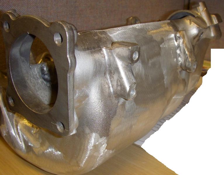
On to the modifications.
First things first, I had to add material to where the factory didn't put it. I welded up the back of the runners so I could make the back of the plenum more flat and not have the protrusions into the air flow region. I also cut off a lot of the unneeded casting items, I'm a pound pincer and I've been liking steak too much lately so every pound off the car counts. The two casting pieces left are for clamping it down on the mill. Not so obvious in this picture, but I also welded up the EGR port in the plenum area and built up the throttle body inlet area (which you can not see at all) to help soften the transition into the plenum.
I also took the opportunity to eliminate the EGR passage. I'll be blocking the EGR port off inside of the head.

Next up I put the manifold on a mill to get rid of the majority of the dividers. I took some pics, but didn't check them before I got out the grinder and did the porting. The pics didn't turn out, so I don't have anything to show at this stage.
Here are the dividers after some port work though. This is looking into the throttle body inlet, similar to the picture in the post above. I'll post the dimensions of how much I cut out and the final runner lengths tomorrow.

One more picture of the runner dividers and of the throttle body inlet. In this one, you can see where I built up near the throttle body.

First things first, I had to add material to where the factory didn't put it. I welded up the back of the runners so I could make the back of the plenum more flat and not have the protrusions into the air flow region. I also cut off a lot of the unneeded casting items, I'm a pound pincer and I've been liking steak too much lately so every pound off the car counts.
The two casting pieces left are for clamping it down on the mill. Not so obvious in this picture, but I also welded up the EGR port in the plenum area and built up the throttle body inlet area (which you can not see at all) to help soften the transition into the plenum.I also took the opportunity to eliminate the EGR passage. I'll be blocking the EGR port off inside of the head.
Next up I put the manifold on a mill to get rid of the majority of the dividers. I took some pics, but didn't check them before I got out the grinder and did the porting. The pics didn't turn out, so I don't have anything to show at this stage.
Here are the dividers after some port work though. This is looking into the throttle body inlet, similar to the picture in the post above. I'll post the dimensions of how much I cut out and the final runner lengths tomorrow.
One more picture of the runner dividers and of the throttle body inlet. In this one, you can see where I built up near the throttle body.
Last edited by 03whitegsr; Jul 5, 2009 at 05:07 PM.
Jul 5, 2009, 04:45 PM
#3
My take and experience on runner lengths, and other manifold design characteristics.
I helped a friend build an intake manifold for his STI several years ago and at the time, we were in slightly uncharted territory. At the start of the project, to our knowledge, nobody had slapped a GT42 or larger turbo on the EJ25. My friend has always been the ambitious type so he wanted to try it out. He was concerned about the spool though and so he asked for my help in designing a manifold package that would help the turbo spool as quickly as possible without choking it up top.
The flat-4s have some features that make it very easy to get a long runner intake manifold on them. Primarily, you have the room since the manifold sits on top of the block and spans from side to side. The only thing really limiting you is the hoodline. The STI has quite a bit of space above the block so we were able to make an intake manifold with roughly 15" of runner length from the back of the valve to the inlet of the runner. 15 inches of runner will give you a torque peak of roughly 5800-6000 RPM (using some very simplified experimentally developed equations).
To keep from choking the top end, we used fairly large runners. The head also had A LOT of port work and some fairly aggressive cams. Off the top of my head, I think the head flowed like 320 CFM/port at 28" on the intake side and the cams had around 250 degree of duration at 0.050" valve lift. I believe the smallest runner cross section was ~2300 mm^2. Also to improve flow across the RPM range, we used tapered inlet trumpets that protruded off the floor of the plenum. On top of all this, we used a fairly large plenum volume. I believe it was around 5.0L, roughly twice the engine displacement.
On testing of the setup, we got exactly what we were after. Actually, even better then what we had hoped for. With a GT4202 on a twin scroll exhaust manifold, the car reached 29 PSI on the street by ~4600 RPM. On the Dyno, the car was just shy of 600 ft-lbs of torque at 29 PSI of boost. The power curve was excellent too, as it hit within 30 HP of peak by 6500 RPM, actual peak at 7500 RPM and then held that peak to 8500 RPM redline, never actually dropping power but holding solid throughout the RPM range. Based on MAP, IDC, AFR, etc. I was able to calculate approximate engine VE across the RPM range. At peak torque, calculated engine VE was ~112% and engine VE at 8500 was around 100%. On the street, the power band was absolutely ridiculous, breaking 275 wide M&H drag radials loose on any crack or piece of gravel on the road. The boost came on instantly above 4500 RPM and even below 4500 RPM, the car had NO PROBLEM pulling away at any engine speed with absolute authority.
So how does any of this relate to the stock EVO manifold? Below is a picture of roughly the stock intake manifold runner geometry.

First thing is runner taper. In the drawing, you can see the manifold has a considerable amount of taper as the airflow travels from the plenum to the valve throat area. At the cylinder head the port measures 58mm wide by 28.5mm tall with roughly a 12.5mm radius in the corners once you port match the runner to the OEM gasket. This is 1520mm^2 of port area. At the plenum, the factory runner inlets measure 58mm square with the same 12.5mm corner radius making for 3230mm^2 of inlet area. If you go by average runner length, this would be ~7 degrees of runner taper. A large amount by most of what I have seen others post but still within the realm of what you will find in various high performance based references. Much like the STI manifold using tapered trumpets to increase overall powerband, Mitsubishi did a similar thing to the OEM manifold.
Second, runner length. This is where some may greatly disagree with me, so I will merely list my reference and allow everybody to draw their own conclusions. I will however explain what the reference recommends for those not interested in reading a 500+ page book on manifold design . This is an SAE sponsored book written by some of the guys behind the engine modeling software that many OEM manufactures use to design engine systems. I wouldn’t recommend it to most, as it is A LOT of mathematical derivation of partial differential equations. Its engine nerdism to the 10th degree.
http://www.amazon.com/gp/product/1860582095
In this reference, they talk in great detail about runner length. The biggest issue they have is how you computer simulate curved runners, and if possible to do it 1-D to reduce computational time. The issue with curved runners is that the majority of airflow in the runner flows along the largest radius because of inertia. Similarly, the pressure pulses that cause resonance pulse flow do all kinds of interesting things in this situation. Their recommendation is to use a number that is somewhere between the average runner length (green in the picture above) and the longest runner length (purple on the OEM manifold). The red line in the picture is a rough estimate of what this actual length would be and how the majority of the airflow would actually want to flow. For the tech geeks out there, I have listed some basic measurements I took off the stock intake manifold below. Measurement are in mm.

Based on the measurements I have taken and the recommendations of the reference above, the factory manifold has an effective runner length of approximately 15” (from plenum inlet area to valve face). This again corresponds to roughly a torque peak of 5800 RPM. You should also note that the OEM did an EXCELLENT job of getting this effective runner length VERY CLOSE to even on all 4 cylinders. +/- 3mm in all reality is well within the limits of error of the measurements I took. The runners could very easily be perfectly the same length. Curved runners are THE ONLY way you are going to stuff 15" of runner into the EVO engine bay. Mitsubishi knew this and that is why the manifold doesn't have a straight runner or something more similar to the B18C5 manifold that Honda produced. Honda however targets conisderably higher torque peaks because of the VTEC cam arrangement and didn't need to stuff 15" of runner under the hood. 12"-13" of smoothly curved runner met their needs.
So how did Mits get the runners all even? Referring back to the picture above, it becomes a little more obvious.
You’ll notice the bottom of the runners do not sit even. Cylinder 1 sits the highest up and the height tapers over to runner 4. This is done because runner 1, 2, and 3 have to curve over towards the timing belt to line up with the head port. Cylinder 4 on the other hand goes straight from the plenum to the head port when looking straight onto the manifold from the angle in the picture. This difference in height is done by varying the runner centerline radius. The further to the right you go, the smaller the radius. Also, if you were to look at the manifold from the top, you’ll see that runners 3 and 4 sit about even, but runners 1 and 2 sit closer to the engine. This makes things interesting on the inside of the plenum and definitely complicated the porting process.
It's getting quite long now, so I'll try and throw in one more little bit of info before I wrap this post up. Runner inlets.
I see talk all the time about raised runner inlets. I use to be a big believer in this and for only one reason, when talking inlet flow losses, a tube inlet that is up off the floor with the correct inlet profile WILL flow better then a radius on the floor of the port. HOWEVER, the difference in flow losses in marginal. Off the top of my head, the difference between a large radius on the floor and the SAE described "ideal" tube inlet that sits up off the floor is only like a 2% difference in choke flow capabilities.
The down side to raised runners is they JACK UP FLOW in the plenum. Yes, it reduces losses at the inlet, but what good does that do if the front runner messes up the airflow for every other runner? Yes, I'm sure it is possible to design a plenum that would work VERY WELL with raised trumpets. But within the constraints of the EVO engine compartment, I feel it would be VERY difficult to do this. No question though, in an ideal situation, the raised inlet is superior, and hence the reason you see them on cars like the Ferrari F1 engine and the BMW GT2/3 cars.
Back to the EVO though. The OEM manifold provides a very smooth inlet to the runners by joining the plenum floor and roof smoothly to the runner roof and floor. The only issue I see with regards to runner inlets on the OEM manifold is that they have Siamesed the runners together, which means you WILL NOT get the nice large radius on the sides. Honestly, this is the one area I believe an aftermarket company could make a significant improvement on the OEM EVO manifold. Space the runners out so every runner is identical and this would provide that nice smooth radius on the sides. I honestly have NO IDEA if it would actually make a difference in the real world though. Futher, it likely won't fit anyway because of the ABS pump sitting on the firewall.
Later, I'll talk about cast vs. sheetmetal and maybe try and get into airflow tumble and its benefits. Make no mistake, Mitsubishi has definitely done some things in the head and the manifold to promote charge swirl/tumble.
I helped a friend build an intake manifold for his STI several years ago and at the time, we were in slightly uncharted territory. At the start of the project, to our knowledge, nobody had slapped a GT42 or larger turbo on the EJ25. My friend has always been the ambitious type so he wanted to try it out. He was concerned about the spool though and so he asked for my help in designing a manifold package that would help the turbo spool as quickly as possible without choking it up top.
The flat-4s have some features that make it very easy to get a long runner intake manifold on them. Primarily, you have the room since the manifold sits on top of the block and spans from side to side. The only thing really limiting you is the hoodline. The STI has quite a bit of space above the block so we were able to make an intake manifold with roughly 15" of runner length from the back of the valve to the inlet of the runner. 15 inches of runner will give you a torque peak of roughly 5800-6000 RPM (using some very simplified experimentally developed equations).
To keep from choking the top end, we used fairly large runners. The head also had A LOT of port work and some fairly aggressive cams. Off the top of my head, I think the head flowed like 320 CFM/port at 28" on the intake side and the cams had around 250 degree of duration at 0.050" valve lift. I believe the smallest runner cross section was ~2300 mm^2. Also to improve flow across the RPM range, we used tapered inlet trumpets that protruded off the floor of the plenum. On top of all this, we used a fairly large plenum volume. I believe it was around 5.0L, roughly twice the engine displacement.
On testing of the setup, we got exactly what we were after. Actually, even better then what we had hoped for. With a GT4202 on a twin scroll exhaust manifold, the car reached 29 PSI on the street by ~4600 RPM. On the Dyno, the car was just shy of 600 ft-lbs of torque at 29 PSI of boost. The power curve was excellent too, as it hit within 30 HP of peak by 6500 RPM, actual peak at 7500 RPM and then held that peak to 8500 RPM redline, never actually dropping power but holding solid throughout the RPM range. Based on MAP, IDC, AFR, etc. I was able to calculate approximate engine VE across the RPM range. At peak torque, calculated engine VE was ~112% and engine VE at 8500 was around 100%. On the street, the power band was absolutely ridiculous, breaking 275 wide M&H drag radials loose on any crack or piece of gravel on the road. The boost came on instantly above 4500 RPM and even below 4500 RPM, the car had NO PROBLEM pulling away at any engine speed with absolute authority.
So how does any of this relate to the stock EVO manifold? Below is a picture of roughly the stock intake manifold runner geometry.
First thing is runner taper. In the drawing, you can see the manifold has a considerable amount of taper as the airflow travels from the plenum to the valve throat area. At the cylinder head the port measures 58mm wide by 28.5mm tall with roughly a 12.5mm radius in the corners once you port match the runner to the OEM gasket. This is 1520mm^2 of port area. At the plenum, the factory runner inlets measure 58mm square with the same 12.5mm corner radius making for 3230mm^2 of inlet area. If you go by average runner length, this would be ~7 degrees of runner taper. A large amount by most of what I have seen others post but still within the realm of what you will find in various high performance based references. Much like the STI manifold using tapered trumpets to increase overall powerband, Mitsubishi did a similar thing to the OEM manifold.
Second, runner length. This is where some may greatly disagree with me, so I will merely list my reference and allow everybody to draw their own conclusions. I will however explain what the reference recommends for those not interested in reading a 500+ page book on manifold design . This is an SAE sponsored book written by some of the guys behind the engine modeling software that many OEM manufactures use to design engine systems. I wouldn’t recommend it to most, as it is A LOT of mathematical derivation of partial differential equations. Its engine nerdism to the 10th degree.
http://www.amazon.com/gp/product/1860582095
In this reference, they talk in great detail about runner length. The biggest issue they have is how you computer simulate curved runners, and if possible to do it 1-D to reduce computational time. The issue with curved runners is that the majority of airflow in the runner flows along the largest radius because of inertia. Similarly, the pressure pulses that cause resonance pulse flow do all kinds of interesting things in this situation. Their recommendation is to use a number that is somewhere between the average runner length (green in the picture above) and the longest runner length (purple on the OEM manifold). The red line in the picture is a rough estimate of what this actual length would be and how the majority of the airflow would actually want to flow. For the tech geeks out there, I have listed some basic measurements I took off the stock intake manifold below. Measurement are in mm.
Based on the measurements I have taken and the recommendations of the reference above, the factory manifold has an effective runner length of approximately 15” (from plenum inlet area to valve face). This again corresponds to roughly a torque peak of 5800 RPM. You should also note that the OEM did an EXCELLENT job of getting this effective runner length VERY CLOSE to even on all 4 cylinders. +/- 3mm in all reality is well within the limits of error of the measurements I took. The runners could very easily be perfectly the same length. Curved runners are THE ONLY way you are going to stuff 15" of runner into the EVO engine bay. Mitsubishi knew this and that is why the manifold doesn't have a straight runner or something more similar to the B18C5 manifold that Honda produced. Honda however targets conisderably higher torque peaks because of the VTEC cam arrangement and didn't need to stuff 15" of runner under the hood. 12"-13" of smoothly curved runner met their needs.
So how did Mits get the runners all even? Referring back to the picture above, it becomes a little more obvious.
You’ll notice the bottom of the runners do not sit even. Cylinder 1 sits the highest up and the height tapers over to runner 4. This is done because runner 1, 2, and 3 have to curve over towards the timing belt to line up with the head port. Cylinder 4 on the other hand goes straight from the plenum to the head port when looking straight onto the manifold from the angle in the picture. This difference in height is done by varying the runner centerline radius. The further to the right you go, the smaller the radius. Also, if you were to look at the manifold from the top, you’ll see that runners 3 and 4 sit about even, but runners 1 and 2 sit closer to the engine. This makes things interesting on the inside of the plenum and definitely complicated the porting process.
It's getting quite long now, so I'll try and throw in one more little bit of info before I wrap this post up. Runner inlets.
I see talk all the time about raised runner inlets. I use to be a big believer in this and for only one reason, when talking inlet flow losses, a tube inlet that is up off the floor with the correct inlet profile WILL flow better then a radius on the floor of the port. HOWEVER, the difference in flow losses in marginal. Off the top of my head, the difference between a large radius on the floor and the SAE described "ideal" tube inlet that sits up off the floor is only like a 2% difference in choke flow capabilities.
The down side to raised runners is they JACK UP FLOW in the plenum. Yes, it reduces losses at the inlet, but what good does that do if the front runner messes up the airflow for every other runner? Yes, I'm sure it is possible to design a plenum that would work VERY WELL with raised trumpets. But within the constraints of the EVO engine compartment, I feel it would be VERY difficult to do this. No question though, in an ideal situation, the raised inlet is superior, and hence the reason you see them on cars like the Ferrari F1 engine and the BMW GT2/3 cars.
Back to the EVO though. The OEM manifold provides a very smooth inlet to the runners by joining the plenum floor and roof smoothly to the runner roof and floor. The only issue I see with regards to runner inlets on the OEM manifold is that they have Siamesed the runners together, which means you WILL NOT get the nice large radius on the sides. Honestly, this is the one area I believe an aftermarket company could make a significant improvement on the OEM EVO manifold. Space the runners out so every runner is identical and this would provide that nice smooth radius on the sides. I honestly have NO IDEA if it would actually make a difference in the real world though. Futher, it likely won't fit anyway because of the ABS pump sitting on the firewall.
Later, I'll talk about cast vs. sheetmetal and maybe try and get into airflow tumble and its benefits. Make no mistake, Mitsubishi has definitely done some things in the head and the manifold to promote charge swirl/tumble.
Last edited by 03whitegsr; Jul 6, 2009 at 01:20 PM.
Jul 5, 2009, 04:53 PM
#4
Glad to see you doing this on your own. I've outlined all of what you are doing already in the flow bench/dyno testing thread. If you aren't going to do a bunch of welding to the back side of that intake manifold you will never get the flow even on a flow bench, which in the end has no relevance to what it does on the dyno. If the car is under 600 whp on our dyno the best thing you can do for the complete power range is to simply port the intake with it all intact and open up the throttle body hole. I'd guess I've spent more time messing with intakes and testing everyone of them I could get my hands on than anyone else.
It is fun to screw with, I'm not getting down on what you are doing so don't take it wrong. It's just all been done.
There is a new intake out from Skunk I just ordered. I am guessing, from looking at it, it is going to be a top performer and it's cheap.
It is fun to screw with, I'm not getting down on what you are doing so don't take it wrong. It's just all been done.
There is a new intake out from Skunk I just ordered. I am guessing, from looking at it, it is going to be a top performer and it's cheap.
Jul 5, 2009, 04:58 PM
#5
Glad to see you doing this on your own. I've outlined all of what you are doing already in the flow bench/dyno testing thread. If you aren't going to do a bunch of welding to the back side of that intake manifold you will never get the flow even on a flow bench, which in the end has no relevance to what it does on the dyno.

I don't think you had any pictures though, and no disrespect, but you posted incorrect runner lengths in your thread. More on that tomorrow.
If the car is under 600 whp on our dyno the best thing you can do for the complete power range is to simply port the intake with it all intact and open up the throttle body hole. I'd guess I've spent more time messing with intakes and testing everyone of them I could get my hands on than anyone else.
It is fun to screw with, I'm not getting down on what you are doing so don't take it wrong. It's just all been done.
There is a new intake out from Skunk I just ordered. I am guessing, from looking at it, it is going to be a top performer and it's cheap.
It is fun to screw with, I'm not getting down on what you are doing so don't take it wrong. It's just all been done.
There is a new intake out from Skunk I just ordered. I am guessing, from looking at it, it is going to be a top performer and it's cheap.
The way I see it, if a company starts a thread on intake manifold design, it kind of eliminates the chance for open conversation because you have one shop vs. another taking shape. On the other hand, I have zero vested interest and I HOPE every company out there makes comments of what I'm doing right or wrong. I see the potential for a thread that could really increase the knowledge of those looking for it without it being a Shop X vs. Shop Y battle.
Last edited by 03whitegsr; Jul 5, 2009 at 05:05 PM.

Trending Topics
Jul 5, 2009, 05:12 PM
#9
I wish I had gotten a good shot of #1. Mitsubishi did some interesting things to that runner and it definitely made it a PITA to get everything as close to even as possible.
I know a guy local that has a flow bench that I may be able to throw this on. However, I didn't baseline this manifold because I'd have to make an adapter plate to get it on his bench. If somebody local has a manifold laying around, I may be able to do a comparison between the two. I honestly don't really care though as I'm not out to sell anything.
David has done a phenomenal job comparing flowbech numbers to power. I wish I had the time and equipment to do that. I envy you David. I love messing with this stuff. Hell, half my posts are just me being jealous of you having a Dyno and a flow bench.
Sorry about that. Didn't mean to come off like an *******, it's just in my nature. Even when I don't want to be a dick, it just happens.
Last edited by 03whitegsr; Jul 5, 2009 at 05:20 PM.
Jul 5, 2009, 05:47 PM
#10
No problem, I'm the President of the ******* club.
I can flow bench your finished product if you like. Confidentially or publically. It's about $100 to flow it. I actually need to flow the one we built too so I could do them both at the same time and maybe save you a bit.
Remember though, the flow bench results don't mean jack.
I can flow bench your finished product if you like. Confidentially or publically. It's about $100 to flow it. I actually need to flow the one we built too so I could do them both at the same time and maybe save you a bit.
Remember though, the flow bench results don't mean jack.
 Jul 6, 2009, 07:09 AM
#12
My biggest problem at this point is that I would like to double weld the front plate back on and there is no way I can get my current torch in there that far.
<- needs a longer torch
Thanks for the offer David, but I'm not all that worried about it. Looking back in your thread a bit, I think I really misunderstood/missed what you did on your testing.
When I read that a while back before I started the project, I was thinking you just smoothed out the smaller bumps and such in the plenum. I didn't realize you did the same thing I did on this. Picture being worth 1000 words, I guess.
I'm not too worried about it, but now I'm even more curious how the hell Indy got another 50 CFM and balanced them out so well on the V2. Wish I had the money to grab one just to see how his genius *** did it just so I could learn from the master. Oh well, won't make much of a difference on my setup anyway.
<- needs a longer torch
Thanks for the offer David, but I'm not all that worried about it. Looking back in your thread a bit, I think I really misunderstood/missed what you did on your testing.
Originally Posted by davidbuschur
Stock intake-stock throttle body
#4-327, #3-308, #2-300, #1-300
Runner length on #4 runner is 10"
Total CFM 1235
BR ported intake with runners cut down and welding on back of plenum to smooth out bumps on back side of plenum
#4-327, #3-313, #2-313, #1-317
Runner length on #4 runner, 9"
Total CFM 1270
#4-327, #3-308, #2-300, #1-300
Runner length on #4 runner is 10"
Total CFM 1235
BR ported intake with runners cut down and welding on back of plenum to smooth out bumps on back side of plenum
#4-327, #3-313, #2-313, #1-317
Runner length on #4 runner, 9"
Total CFM 1270
I'm not too worried about it, but now I'm even more curious how the hell Indy got another 50 CFM and balanced them out so well on the V2. Wish I had the money to grab one just to see how his genius *** did it just so I could learn from the master. Oh well, won't make much of a difference on my setup anyway.
Last edited by 03whitegsr; Jul 6, 2009 at 09:52 AM.
Jul 6, 2009, 08:21 AM
#13
Evolved Member
iTrader: (62)
Join Date: Feb 2004
Location: Redmond - Lake Tapps ,WA
Posts: 3,336
Likes: 0
Received 6 Likes
on
6 Posts
Looks like a fun project Mike. That's what makes it cool is learning the stuff first hand, giving yourself something to do and saving some monies.
What did you use to cut it open, a die grinder with a cutoff wheel?
I get emails about that issue all the time, I'll forward them to you.
What did you use to cut it open, a die grinder with a cutoff wheel?
I get emails about that issue all the time, I'll forward them to you.
Last edited by jid2; Jul 6, 2009 at 08:25 AM.
Jul 6, 2009, 09:30 AM
#14
Wilson balanced the runners, that was where the work was done. There is welding done to the actual runners on the V2's and a lot of port work was done after the welding. The largest gains in balancing flow is just from working the inside of the plenum like you are doing.
Jul 6, 2009, 09:45 AM
#15
David, I've made the assumption all along that the Wilson manifold did not alter the exterior of the manifold. This would essentially limit them to nearly stock runners as the casting is quite thin (roughly 2.0mm thick). Other than building things up internally, I didn't see them modifying the runners much.
However, after looking at a few things in the runner and realizing that may have just been a stupid assumption, I think I have drastically underestimated the amount of work done by Indy and Wilson. I am starting to see where the $1500 price tag may have come from.
JID2, forward those emails on to flintownkilla.
Oh yeah, updated post 3 with a bunch more shizznit.
Last edited by 03whitegsr; Jul 6, 2009 at 09:55 AM.