When you click on links to various merchants on this site and make a purchase, this can result in this site earning a commission. Affiliate programs and affiliations include, but are not limited to, the eBay Partner Network.
I was reading through SH-2 Hardware manual, as one does, and the Advanced User Debugger (AUD) caught my interest. This is an on-chip hardware interface that is piped into everything but runs independent of the rest of the hardware. the AUD allows read/write access to all of the memory at high speed. If I'm not mistaken a couple orders of magnitude faster then K-line, and without any cpu overhead. To me this seems like a really good way to do some very fast logging and possibly flexfuel, live tuning, auto tuning etc etc.. After doing some searching I didn't really turn up anyone else playing with this interface. I don't know if that's a good sign or not but I want to try and explore what is possible with it. If anyone has any information or experience on this topic please post it, I would love to hear about it. I imagine a daughter board interface, something like a gaming console mod is probably what will be needed to work with this. I'll have to get my hands on a spare ecu to start playing around with it to see what kind of rabbit hole this is. So I'll be looking to get one soon(PM me if you have a spare you want to sell).
Debug interfaces like this are usually disabled on shipping products. It's possible that Mitsubishi left it open, or maybe the Renasas part doesn't even have the ability to disable it. If the interface was enabled, you'd still have a few expensive software and hardware hurdles before you could access it. These protocols are usually obscure enough that I wouldn't expect to use it anywhere except with official Renesas tooling.
You don't need an out of band interface for fast memory access, though. If you search through the forum you can find the old DMA patch.
My 8859 ROM is patched with the DMA code. I have a small, clunky program that takes an Evoscan .XML and produces log files with something like 10x the frequency of normal Evoscan logging. At one point someone had some livemap software that used the DMA hooks, but that project died.
Thx for the feedback. I'm trying to teach myself embedded hardware development, so this was kind of a project I figured I could use to learn from. If it's a dead end so be it, but I want to try and run it to ground. I don't know if you read the protocol data they provided in the doc I linked in, but do you think that is enough to go by for me to eventually be able to write a protocol?
This is very interesting, I look forward to seeing what you find. Unfortunately I don't have an extra to tear apart, otherwise I'd love to mess with this as well. You can probably just wire those pins to a serial connection, the hard part is going to be figuring out how to actually communicate with the board.
This will be an excellent project, I'll definitely be following to see what you find, thanks for taking the time to tear into this!
Thanks, I'm hoping the data in section 17.4-17.5 as well as other parts of the manual will be enough to go off of.
Thanks, I'm hoping the data in section 17.4-17.5 as well as other parts of the manual will be enough to go off of.
It looks like they detail how to initialize communications, which is pretty straightforward, but I'm at a loss as to how to interpret the data being sent. To be fair I'm a noob with embedded systems, so that doesn't say much haha. I'll go ahead and read through the manual once I'm done with work and see if I notice anything interesting. Best of luck, let us know what you find in your testing!
It looks like they detail how to initialize communications, which is pretty straightforward, but I'm at a loss as to how to interpret the data being sent. To be fair I'm a noob with embedded systems, so that doesn't say much haha. I'll go ahead and read through the manual once I'm done with work and see if I notice anything interesting. Best of luck, let us know what you find in your testing!
Getting it to work is step one, figuring out where everything lives in memory is probably step 2, but I'm hoping that information already exists or at least can be figured out with existing knowledge.
looking through the manual i didn't see a way to disable the aud in software. Which would make sense otherwise it would probably suck at its job. So if mitsubishi did disable it, it would be through hardware like a pull up / down on one of the pins. So if that's the case i'll find that by testing the the board and worst case desolder the aud pins from the board. Hopefully though it would just be something like desoldering a resistor if it is locked.
looking through the manual i didn't see a way to disable the aud in software. Which would make sense otherwise it would probably suck at its job. So if mitsubishi did disable it, it would be through hardware like a pull up / down on one of the pins. So if that's the case i'll find that by testing the the board and worst case desolder the aud pins from the board. Hopefully though it would just be something like desoldering a resistor if it is locked.
The protection section starts on page 717. I couldn't find any references about disabling the AUD interface either, which is kind of surprising.
I'm surprised. On most embedded platforms it's standard practice to blow the JTAG fuses during manufacturing to prevent anyone else from using the debug pins for reverse engineering. AUD is a similar backdoor interface, so I just assumed Renesas would provide some option to disable it in production. I wonder how many other past ECU hackers made the same assumption without checking. Nice work.
Thanks for the tip ill read up. That makes sense everyone wants to protect their IP, and I didn't even know burning out chip features was a thing. So I'll sum this up as beginners luck
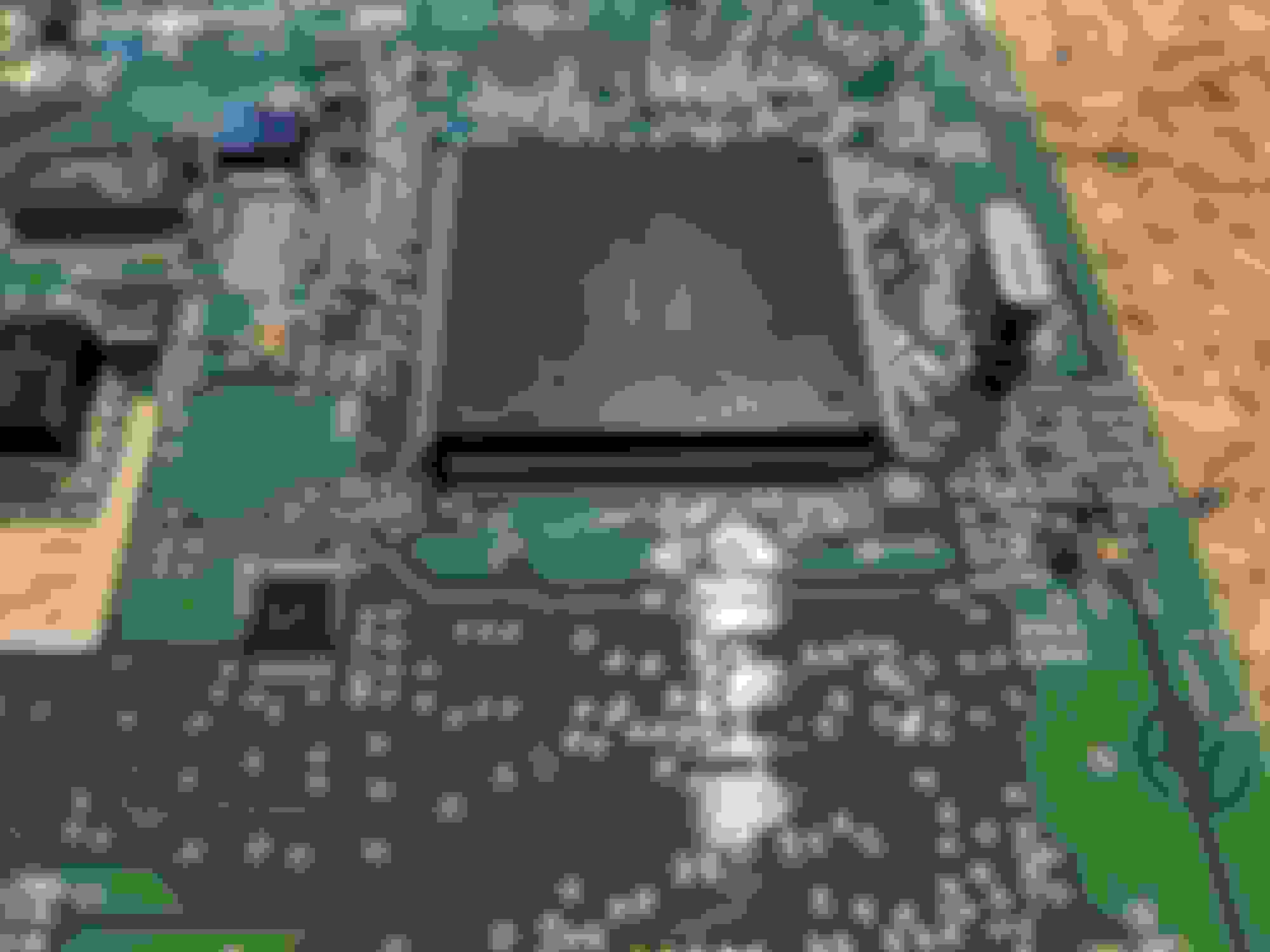
I've got my hands on an ECU. Here is a pic of the chip on the pcb. It doesn't appear the AUD pins are tied into anything. The pins are pretty small so I'll have to research a technique to attach to them.
It's very difficult to get clips attached to 0.5mm pitch QFP packages like that. I haven't had great luck with anything cheap. You could try these, but I can't vouch for them: https://www.digikey.com/product-deta...100-ND/5028882
Attaching 30AWG wire with a high quality soldering iron is the ideal route. If you have good flux, a fine tip, good lighting, and steady hands it isn't too bad. Just be careful not to lift any traces or pins in the process and you should be fine.
Thanks for the tips! What I have read so far agrees with what your saying. After watching some youtube vids it seems pretty doable. I just need to grab some wire and a new tip before I take a stab at it. My hakko iron isn't the best, but its not garbage so hopefully it will do.
 Mar 25, 2019, 10:31 AM