There are failsafes, failsafes and failsafes...

 Oct 18, 2008, 10:54 AM
#92
Former Sponsor
Thread Starter
iTrader: (5)

Join Date: Aug 2005
Location: England
Posts: 2,236
Likes: 0
Received 0 Likes
on
0 Posts
Everyone must realize that this type of flow meter is a measure of VOLUMETRIC flow rate and is used for reliability and repeatability purposes. It is NOT, i repeat NOT MASS FLOW rate which would be the actual mass of fluid per unit of time.
Do you see that restriction in the middle. it is there so you can measure pressure differential. Mathmatically the differential pressure is a square of fluid velocity. Differential type flow meters need corrections for temperature or pressure changes which I think most if not all systems do not do this.
why dont meth injection company's make a MASS flow meter like the Coriolis method or thermal mass meter.
The sensor is a based on an magnetic turbine wheel, rotational speed is picked up by a Hall effect sensor in the middle. The machined slot is for allowing the sensor to get closer to the wheel. It is not a restrictor. See the transparent sensor tube - water is spun around the surface of inner bore to ensure maximum turbine/fluid contact. An Aquamist design we have copyright to, we manufacture them in house.
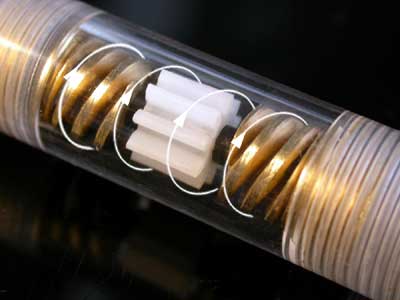
I am afraid your maths does not apply to this sensor. Nonetheless, it is a nice bit of information.

Last edited by Richard L; Oct 29, 2008 at 01:06 AM.
Oct 18, 2008, 11:22 AM
#93
Former Sponsor
Thread Starter
iTrader: (5)
Join Date: Aug 2005
Location: England
Posts: 2,236
Likes: 0
Received 0 Likes
on
0 Posts
A turbine based wheel flow sensor's rotational speed is not linear to flow, this is due to variation of fluid molecules hitting the turbine in a random fashion. This is particually notable in this type of applications, where flow is affected by the pressure ripple from the pump diaphragm. We don't have the luxury of a pulseless supply.
As the DDS3 is designed to be a universal flow monitoring device, we have to overcome some of the extreme pressure pulses from a PPS system. Particularly between the low DC% and high DC%. Low DC have well spaced out ripples and high DC has the "on-demand" induced ripples (as much as 20psi).
In order to give a reasonable accuracy over all type of systems, we mapped the turbine speed against the actual flow, over several flow ranges (a lot as we are extending the flow range). Each range is stored inside the mircochip. When you put different voltages into the green wire, it is like turning pages of the stored files. Other house-keeping algorithm is also employed to keep the data processing stable.
I cannot explain the green wire's function in a less complicated way.
Sep 10, 2010, 02:44 PM
#95
Account Disabled

Join Date: Feb 2010
Location: California
Posts: 54
Likes: 0
Received 0 Likes
on
0 Posts
Well I'm glad that we can finally contribute something to this thread:
https://www.evolutionm.net/forums/wa...lsafe-aem.html
https://www.evolutionm.net/forums/wa...lsafe-aem.html
Dec 20, 2010, 03:51 PM
#96
Former Sponsor

Join Date: Dec 2003
Location: Los Angeles, CA
Posts: 48
Likes: 0
Received 0 Likes
on
0 Posts
One of the huge benefits of the AEM Injection Monitor WMI Failsafe is it really is the first "progressive" failsafe.
Any fail safe with only one minimum flow threshold is bound to be a compromise. If you want to be able to catch full power flow decreases as low as 10% you have to set your failsafe threshold so high that the vast majority of the time it is not even checking for a failure or worse, reports false triggers. Alternately if you set it low to catch the flow failure early then it will be blind to the injector clogging up and could let the system flow significantly less at WOT than you expect without triggering a failure.
Having a fail safe that can't "see" that you have a progressive controller is a huge liability. The danger in designing simple is the risk of over simplifying and that can easily cost you a motor.
Single threshold fail safes are great if you have a hobbs-switch activated (stage 1) system. If you have a progressive controller wouldn't you want a progressive fail safe?
Jan 6, 2013, 08:46 AM
#97
Former Sponsor
Thread Starter
iTrader: (5)
Join Date: Aug 2005
Location: England
Posts: 2,236
Likes: 0
Received 0 Likes
on
0 Posts
This thread is due for an update...
Aquamist is the first to develop a turbine flow sensor to read flow in real time in 2001. A good few years late, other companies followed with varied success. It was most probably using an off-the-shelf plastic body sensor in harsh engine bay environment. Over the next few years, every wmi makers settled on the turbine wheel type instead of the paddle wheel type due to cost. But still plastic body based whilst aquamist continue to employ the metal type. Totally reliability.
Fast forward this to 2013 and after some serious research, a couple of wmi manufactures have stopped offering the plastic flow sensor all together (supplied by GEMsensors.com) and used some alternative methods to detect flow problems. The messages was loud and clear to other wmi makers. These sensors just continued to fail in service, some just after a few months. Whilst this was going on, the aquamist's in house designed and manufactured sensors continue to perform flawlessly.
The most surprising outcome to this is the way the some wmi makers changed the way of marketing the same old sensor. Instead of sourcing a more reliable one, they just tell their customers to reduce the methanol concentration to 50% for safety reasons (wise words indeed) while still marketing their product as methanol injection systems. Unfortunately those sensors continued to be unreliable even after methanol ratio was reduced. There are hundreds of engines at risk out there without a failsafe due to flow sensor failure.
It is a real irony that a failsafe is the first item to fail...
Last edited by Richard L; Jan 6, 2013 at 10:35 PM.
Jan 6, 2013, 09:24 AM
#98
My HFS-3 is still running strong. I purchased it from the pre-release group buy years ago! I only run 100% M1 to boot.
The main reason that I choose and recommend Aquamist product is the customer service and reliability. Some of the vendors who have posted in this thread would not even help people who had purchased their kits. The customer support I have recieved from Aquamist is second to none.
The main reason that I choose and recommend Aquamist product is the customer service and reliability. Some of the vendors who have posted in this thread would not even help people who had purchased their kits. The customer support I have recieved from Aquamist is second to none.
Oct 9, 2013, 09:58 AM
#100
My engine has been punished through the early years of inj kit failsafes. Particularly because I burned anhydrous meoh and never used the aquamist systems. The headaches caused by the other brands however provided the steam which allowed me to develop, piece by piece, a solid failure safe 100% meoh system which is allowing my 120k mi stock block and head to continue solid HP today. That's 100000 +miles of methanol injection on this engine (though the early years should have resulted catastrophically with the failsafe systems I tried).
My system as such seems to be working fine:
Two snow pumps with separate Hobbs control, separate nozzles (1 and 2 each respectively) located 10 inches apart, LC1 WB02 output feeding my ecu via tephra v7. Basically, if my system isn't spraying correctly the afr will lean and the boost solenoid will have 0wgdc. Twin systems primarily used for loads of meoh through only modest sized nozzles which means atomized HP but also provides redundancy.
Of the 8 years of methanol inj, only the last few have given me the piece of mind as carefree WOT driving.
Now after saying this, watch my engine blow up tomorrow lol but at least I can joke
Last edited by C6C6CH3vo; Oct 10, 2013 at 06:53 AM.
Jan 15, 2014, 03:24 AM
#101
Former Sponsor
Thread Starter
iTrader: (5)
Join Date: Aug 2005
Location: England
Posts: 2,236
Likes: 0
Received 0 Likes
on
0 Posts
Two pumps, two hobb switches and two nozzles do ensure flow continuity. If one system fails, the WBO2 sensor will activate failsafe, a good arrangement.
The latter part of failsafe (WBO2) can also work well for a single pump, jet and hobb switch arrangement, providing the same protection for your engine.
Two comments on this:
1. System cost will be doubled but does not double the failsafe but does ensure at least 50% of the flow. Since failsafe is provided by the WB02 sensing.
2. If user decided to run M50/W50, the WB02 will find it a bit more difficult to detect a 25% drop in Meth delivery. This is to assumed there are natural variations across the "lean" and "rich" window when setting the WBO2 tripping point. More failsafe trips will occur as a result.
This arrangement is acceptable if the system is "all on and all off". When it comes to a progressive delivery system, it will not work as the detection window is too narrow for a WBO2 sensor to detect reliably. If you widen the window to offset false trips, the failsafe will be greatly compromised.
Feb 8, 2014, 03:26 AM
#102
Former Sponsor
Thread Starter
iTrader: (5)
Join Date: Aug 2005
Location: England
Posts: 2,236
Likes: 0
Received 0 Likes
on
0 Posts
Progressive Failsafe vs Band-gap Failsafe�
Progressive Failsafe vs Band-gap Failsafe…
If you think the Aquamist failsafe can only detect "too little" or "too much" flow as expected from a fixed failsafe window width, think again. Our competition was preaching this to the masses, but they should have delved a bit deeper before launching their negative marketing campaign.
Simple answer, the “hi-lo” trip can detect a partial clog. If you set the "lo-trip” to 150cc/m and "hi-trip" to 500cc/m, anything outside this window will trip a failsafe. So though it seems Aquamist can only detect “too little” or “too much” flow, if one looks a little bit closer things become more clear…
Suppose the flow is dropped by 10%, (now 135c/m to 450cc/m) due to a partial clog. The failsafe will trip at the "lo side” of the window at the beginning of a spray event. Vice versa, if flow is increased by 10%, (now 165cc to 550cc/m) due to a leaky hose, the failsafe will trip at the "hi side” of the window. So who is not telling the truth?
Aquamist has tried the dynamic window method but it performed badly under a fast dynamic load change on the bench as well as in real world tests. Simple tasks such as a normal gear change will trip the failsafe at 10% error band. The failsafe continues to trip until it is set beyond 40% error band. This is caused by the turbine flow sensor over and under shooting and not keeping pace with the flow change produced by the fast acting valve. The only way to solve this problem is by applying a powerful electronic low-pass filter, but we have discovered that even doing so, the overall failsafe response time is too slow, much slower than the current setup. Consequently, we have decided not to offer this option until we can address the problem satisfactorily. At the present we prefer 10% error to 40%.
Maybe the much hyped up "dynamic-window" failsafe system only works with pump speed systems, which is probably due to the system's inability to respond quickly load changes. A few Aquamist users tried to mix and match and ended up with a very loosely-defined failsafe window and eventually returned to the original band gap method (failsafe window).
The latest HFS4 is equipped with an additional 0-5V input. It can be used in parallel with the standard failsafe. If AFR, EGT or IAT exceeds a certain set level, it will drop boost or switch maps. To us, looking ahead or capturing a problem as it happens, is a far better way, even if there are delays and over generous error bands. Take a closer look at the distribution of the captured flow curves in the advertised images, especially at the lower section of the flow range.
Feb 20, 2017, 07:10 AM
#104
My hobbs switches failed 2 years ago. They don't last, not sure why they are used in aircraft applications.
My new failsafe consists of the same twin pump gig but powered through the cars beefy defrost relay circuit. Relay is simply energized through the factory IC spray output in the ECU which is programmed via tephra V7. The failsafe is twin pump redundancy and the flashed map that dumps WGDC if a certain load is reached and the WBO2 isn't rich enough (+12.9afr for 0.5 seconds). This system should last for many years. Hobbs switches went out after about 3 years, don't use them. If I hadn't had redundancy I could have damaged the engine
My new failsafe consists of the same twin pump gig but powered through the cars beefy defrost relay circuit. Relay is simply energized through the factory IC spray output in the ECU which is programmed via tephra V7. The failsafe is twin pump redundancy and the flashed map that dumps WGDC if a certain load is reached and the WBO2 isn't rich enough (+12.9afr for 0.5 seconds). This system should last for many years. Hobbs switches went out after about 3 years, don't use them. If I hadn't had redundancy I could have damaged the engine
Feb 22, 2017, 09:05 AM
#105
Evolved Member
My hobbs switches failed 2 years ago. They don't last, not sure why they are used in aircraft applications.
My new failsafe consists of the same twin pump gig but powered through the cars beefy defrost relay circuit. Relay is simply energized through the factory IC spray output in the ECU which is programmed via tephra V7. The failsafe is twin pump redundancy and the flashed map that dumps WGDC if a certain load is reached and the WBO2 isn't rich enough (+12.9afr for 0.5 seconds). This system should last for many years. Hobbs switches went out after about 3 years, don't use them. If I hadn't had redundancy I could have damaged the engine
My new failsafe consists of the same twin pump gig but powered through the cars beefy defrost relay circuit. Relay is simply energized through the factory IC spray output in the ECU which is programmed via tephra V7. The failsafe is twin pump redundancy and the flashed map that dumps WGDC if a certain load is reached and the WBO2 isn't rich enough (+12.9afr for 0.5 seconds). This system should last for many years. Hobbs switches went out after about 3 years, don't use them. If I hadn't had redundancy I could have damaged the engine
~Jaraxle