When you click on links to various merchants on this site and make a purchase, this can result in this site earning a commission. Affiliate programs and affiliations include, but are not limited to, the eBay Partner Network.
Your not wrong. Cars are electrical noise crazy! However, the design of using Crydom SSRs for pump control is not something that needs to be concerned with that issue. Crydom relays are top notch, and the pump is directly wired to the battery. I think the design is solid as is, and since the triggers are 3v+ there are no chances of noise causing an unwanted SSR trigger. Thanks for the input, and I certainly don't mind anyone contributing to this little project. A guy at work asked about SELLING this, and I just don't have the energy or greed to drive that...LOL... so it's open source I suppose...
I'm not so much concerned with transients causing false triggers, although that would be a concern. SSR's are fet based and fets fail open so if the ssr fails you lose power to the pump. I get that you like Crydom, but its going to take more then a strong endorsement for me to trust my engine to a device. Nothing in Crydom's material leads me to believe that it can suppress ISO 7637-2 and ISO 10605 type transients. It being hooked up to the battery doesn't make anything better because that's literally the main power rail for the whole car, it will experience all the bad stuff. Crydoms site doesn't list automotive as an application for these devices either, and the datasheet here http://www.crydom.com/en/products/ca...anel-mount.pdf doesn't show any real protection on the control or switching side of the SSR. What the datasheet does show is that for inductive loads you need to add a freewheeling (flyback) diode to the load to protect the device which you haven't done in your setup. So you are going to want to add that for sure.
I'm not so much concerned with transients causing false triggers, although that would be a concern. SSR's are fet based and fets fail open so if the ssr fails you lose power to the pump. I get that you like Crydom, but its going to take more then a strong endorsement for me to trust my engine to a device. Nothing in Crydom's material leads me to believe that it can suppress ISO 7637-2 and ISO 10605 type transients. It being hooked up to the battery doesn't make anything better because that's literally the main power rail for the whole car, it will experience all the bad stuff. Crydoms site doesn't list automotive as an application for these devices either, and the datasheet here http://www.crydom.com/en/products/ca...anel-mount.pdf doesn't show any real protection on the control or switching side of the SSR. What the datasheet does show is that for inductive loads you need to add a freewheeling (flyback) diode to the load to protect the device which you haven't done in your setup. So you are going to want to add that for sure.
Edit: So what I'm saying is all the big nasty stuff that makes auto electrical harsh is connected up to the battery, its the main rail for the car. The starter, the window motors, the blower motor, windshield wipers, radiator fans, all hooked up to the battery. They are all large inductive loads, every time they turn on and off they send huge spikes into the electrical system. Its because of this automotive electrical has to be designed to be extremely rugged. The standard automotive relay may be crude and slow, but it is very rugged and reliable compared to a complex switching circuit. So if something wasn't designed with protection for these kind of wild electrical spikes in mind it can over time or immediately damage the electronics. It's ok if you want to use something not designed to handle this kind of stuff, you just have to add parts around it to protect it.
Biggie Biggie Biggie I didn't see, sometimes your words hypnotize me... Your RIGHT!. I thought the SSR had internal protection for flyback.
I am thinking that the VFT2045BP that I already have (and am using in the current circuit), would be fine for a kickback diode on the motor.
Do you concur with that diode selection for protecting the SSR ?
That is exactly what I was thinking, but I have one already as a spare for the diode in the original circuit design. I just soldered up VERY short leads and connectors to attach directly to the motor. So if you thinking it is anything other than overkill, please let me know ASAP cause I am going to bolt this sucker onto the fuel pump this weekend. I would rather go for overkill than min-spec and have it burn out over time. That was a great catch, I thought this SSR was immune to flyback.
based on the data sheet the diode should be ok. A 30 amp constant current rating would be better but it has 160amp surge so that will probably make it work out fine. Do you know how many amps you are drawing through the diode in your original application?
based on the data sheet the diode should be ok. A 30 amp constant current rating would be better but it has 160amp surge so that will probably make it work out fine. Do you know how many amps you are drawing through the diode in your original application?
When the DW350il is being run at low voltage it pulls under 7.7 amps through the dual voltage power supply diode. Deatschwerks was kind enough to test it at 9v for me and provide the current curve at that voltage.
Just getting around to updating the two drawings. Basically just added the flyback diode across the fuel pump. Now I am wondering if this is the PRIMARY cause of the OEM relays from dying! It sure seems like it could be part of the problem.
Flyback diode added Single large pump design with flyback diode added.
There has to be a way to make that without it looking like a rats nest. Maybe time to make your own board? ;P
I have thought more about making a small metal box version with screw terminals as the only interface. Maybe make the single big in-tank version and see if someone wants to run it. I would want to change it to detect the factory lines going high and therefore making it so you don't have to mess with the factory fuse box terminals like I did.... I would just be worried about someone coming after me if something broke for ANY reason.....
So I have a sketch for version 2.0 of the single BIG pump design that is very simple. It only consists of three diodes and a solid state relay. The parts for this new design are being collected by another Evolutionm member who contacted me for assistance.
Once that version is tested and verified on his vehicle I will be posting that in this thread for anyone to replicate. I have a feeling this one is going to be popular, because it is SUPER SIMPLE yet provides OEM ECU control of a BIG fuel pump with no moving parts. It also no longer requires any changes or connecting to the engine compartment fuse box (no wire running from front to back of vehicle for ECU command status). Detection of what the ECU wants is done by "reading" the stock power wire that already goes to the OEM fuel pump.
This design below is for a SINGLE large pump, but could be changed to run TWO pumps synchronized (in terms of lo/hi power control by ECU).
This new 2.0 design does not require any changes under the hood. The stock relay stays in place, and no wire is run to the back of the car.
Another member of the group here is going to be the first tester of this new solid state simple design.
When the stock ECU and wiring sends 9.5v to the pump the ZENER diode blocks the voltage from triggering the high power solid state relay (SSR).
The 9.5v continues down and just powers the pump. When the ECU asks for HI voltage (13+ volts) the ZENER trips and thus the high power relay is triggered so the fuel pump is powered DIRECTLY by the battery through an inline protection fuse. The 2nd diode prevents this higher power from causing a circular trip of the relay or damaging the ECU and the last diode across the motor protects the SSR from any kickback as the pump is switched from hi to lo or the car is turned off.
I've been working on installing the Single Pump Relay 2.0
Here is a shopping list of everything I've used: 1.) Single Crydom D1D40 Solid State Relay (eBay, new $28) 2.) TWO VFT2045BP diodes (Mouser.com $1.22ea)
3.) Single 1N936B-ND zener diode (Mouser.com $8.63) 4.) 12 gauge silicone wire 10' Red, 10' Black (Amazon.com $11 for the set)
5.) Terminals/Heat Shrink Tubing, Techflex, zip ties (I had all of this already) 5.) Single 12-10 guage (20A) Waterproof Sealed ATO ATC Fuse Holder Assembly (Amazon 5pk $15) 6.) Single Crydom heatsink HS301DR (eBay $20)
7.) Heatsink Thermal Paste/Pad/Tape (Had this already)
8.) 1/4 and 5/16 grommets for the fuel pump cover (Had these in a Harbor Freight Grommet Kit)
9.) (Optional) Knukoncepts Battery Terminals that allow for keeping the stock battery cables**. ($36)
**You could put ring terminals around the bolts on the factory cables, cut the ends off, make new cables, etc. but I liked how clean these install/remove) Right now, I'm at $121 and if you have none of the above there's probably another $15 of misc. supplies putting a scratch build at $136 to replicate my setup. A bit more bargain shopping and skipping the optional stuff should keep you under $100.
Tools used:
Drill and 1/4" and 5/16" drill bits
Good quality wire crimpers
Soldering Iron/Solder
Rivnut gun and rivnuts (or self tapping screws)
Heat gun or torch
10mm wrench
Pry tools
Metric Allen Key Set
I first went about getting all of my wires connected up and cleanly wrapped in some techflex
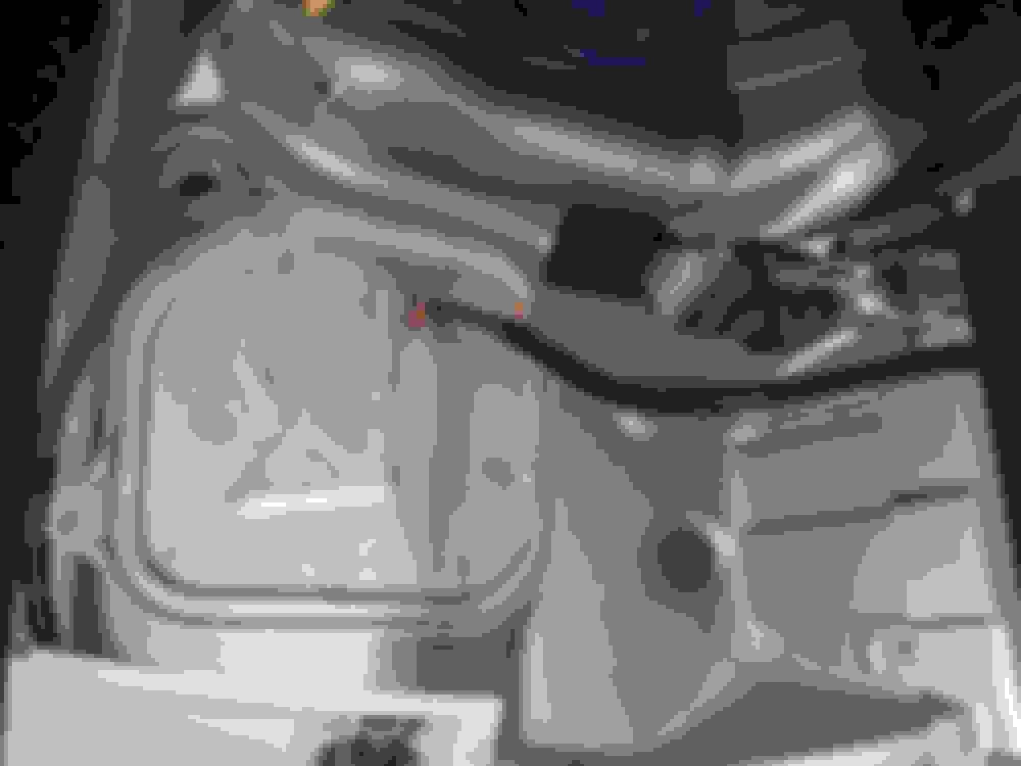
After taking off the battery cover panels and emptying the trunk, this is the space we're working with. I wanted to keep the relay close to the battery and accessible as well as in a space with some air.
Knukoncepts makes a battery terminal that allows you to keep your factory cables unmolested. I put some ferrules on the wire ends so they'd clamp tighter in the terminal block
I mounted they Crydom relay and heatsink to a scrap of plate steel and then put 2 rivnuts in the support brace to attach the assembly to the car
Knukoncepts terminals mounted.
I put the fuse holder where the wiring would have good strain relief but it really should have been closer to the positive terminal. I just didn't like the mounting options as well. This is another rivnut mounting solution.
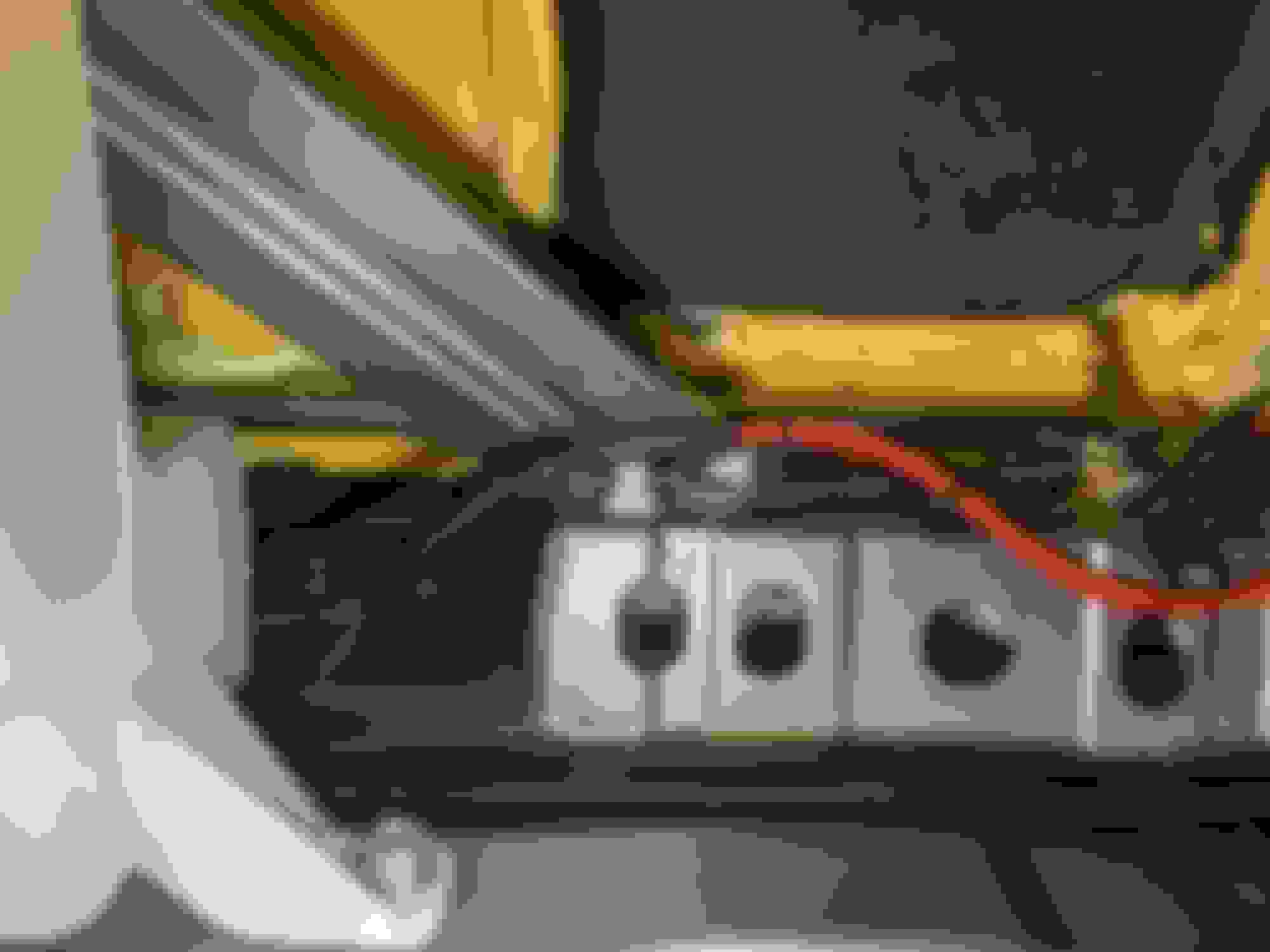
I routed the wiring along the OEM washer hose to keep it away from any sheetmetal edges.
Not wanting to punch through the trunk floor and deal with snaking wiring up and over the tank, I opted to run under the back seat and use a couple of grommets in the OE pump cover. Wiring into the pump housing