


Aquamist HFS-5 system design concept explained...


Aquamist HFS-5 system design concept explained...
.
As the introductory offer is now closed.
Detailed study of the new HFS-5 system and the concept behind the designed.

Design aim of the HFS-5 water/methanol injection system:As the introductory offer is now closed.
Detailed study of the new HFS-5 system and the concept behind the designed.
In order to maximize of effect of water/methanol injection, the rate of delivery should be closely related to the real time engine operating parameters. The first objective is finding a signal that is comparable to the engine’s cooling/octane demand at the exact moment in time.
Finding the signal to match engine’s demand:
Load sensors such as throttle position, mass air flow and MAP sensor are a prime signal source of engine load. But without RPM reference, these sensor are only representing a two dimensional impression. For example, MAF sensor without RPM reference only measures air consumption, regardless of gearing or boost pressure. The engine could be cruising at high speed (less stress) or it can be travelling at 20mph on a rally stage under extreme load and high temperature stress. The same chuck of MAF signal cannot represent the engine’s running condition overall.
Why tracking fuel injector duty cycle:
With the help of the modern engine management system, the same chunk of MAF signal, coupled up with a bunch of signals gathered from sensors such as ‘air temperature’, ‘coolant temperature’ and ‘EGT’ (interpreting the lambda probe’s heater element) and of course, engine speed. It will make an informed judgment when to add or trim fuel depending on the real-time operating environments. The final decision made by the management will be reflected by the duty cycle of the fuel injector. The HFS-5 uses this IDC signal to meter flow.
Picking the correct delivery method and hardware to complete the task:
We have ruled out the variable pump-speed delivery system for a numbers of reasons. Due to the inertia of the rotating mass, variable pump-speed system is not responsive to the fast changing engine load at various throttle openings and engine speed changes, especially during gear shifts. Flow range is narrow due to limited pressure span. It requires 4x the pressure change to produce twice the flow change. Poor atomisation and pulsating line pressure at low pump speed is an inherent characteristic of such a system. Without consistent droplet size is vital to inlet cooling and even cylinder distribution, one will always tune for cylinder receiving the least cooling, resulting over-injection on other cylinders.
HFS-5 chooses the well established method for fluid delivery:
Decision was made to employ the ‘tried and tested’ delivery system similar to a fuel injection system to meter fluid flow. A 150W heavy duty pump is made specially for us by Shurflo USA. Equipped with three 125psi internal by-pass valves provides the regulated system pressure. A surge arrestor/accumulator refines the low-ripple further. A high-speed stainless inline valve completes the line up. This valve is capable of flow over a litre of fluid at 125psi. A dedicated controller reads the fuel injector’s duty cycle % and channels it to the inline valve.
A dash gauge displays the flow information from a digital turbine flow sensor:
Failsafe is serviced by the Aquamist’s proven DDS3 module, which is designed to go further then just detect clogged jet/nozzle and cut hose…..this device can give visual feedback on a partially clogged jet/nozzle. Two switched outputs provide the necessary interface with device such as boost control valve and map switch equipped engine controllers.
HFS-5 meets all criteria of a reliable and highly precise fluid delivery system:
We believe the HFS-5 is the only fluid delivery system that meets the minimum requirement for achieving full integration into your tuning programme, with absolute precision. Tracking the fuel delivery is the most reliable method to meter your water/methanol flow accurately under the whole engine operating range. Anything short of this means having to tailor your fuel map to compensate the irregular fluid quantity ingested by the engine.
Should you decided not to mirror the fuel flow in your future upgrade programme, the HFS-5 system can read a PWM output from a third party engine management controller so a custom water/methanol map can be created.
This one-time offer is a rare opportunity of a life time for you to try out this professional system at a very affordable price. Jack, our US representative will be hosting this offer.
.
We will be posting the pricing details and the link to the introductory offer next week here.
Last edited by Richard L; Jan 26, 2007 at 02:49 PM.
Last edited by Richard L; Jan 21, 2007 at 05:41 PM.
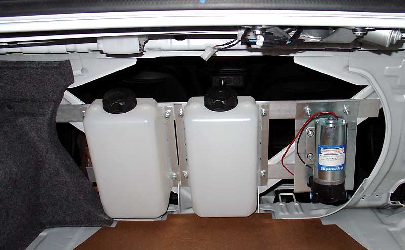
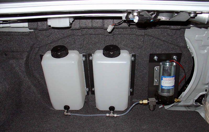
We are unable to supply a water tank, but here is a link to the best place for a tank (price is also very reasonable):
http://fluids.flambeau.com/
Some practical examples:
I believe the pair costed $40.
http://fluids.flambeau.com/
Some practical examples:
I believe the pair costed $40.


Got more questions. Following injector duty sounds great save one problem. The transitional state. When and what turns the pump on? And when does the water start injecting? Is the injection rate a straight pecentage(based on selected size injector) all the time while injecting? Or is the rate ajustable per rpm or load? Another way to word this. Is the hsv injecting at the same duty as the fuel injector? If it is it seems you would have a problem tuning the turn on point.

Hi, the system is turned on via the button on the DDS. The junction box for the DDS3 has a trigger setting that is adjustable. The input for this trigger adjust is MAP/MAF or FIDC (pin 17 on the junction box). The output is FIA2-TRIG (pin 25) which goes to the FIA2 which is hooked up to the fuel injector to get referance.
The HSV sees constant pressure behind it it and the pump maintains the pressure when the button is turned on. The FIA2 looks at FIDC and controls the HSV using this info = water injection is linear to fuel.
Out of the box the trigger adjustment is 50%,
1) if you hooked up your system to use FIDC for the turn on signal the junction box would signal the FIA2 to begin pulsing the HSV to mirror the FIDC when 50% FIDC has been reached, and shuts back down when below 50%
2) if you hooked up your system to use MAP/MAF for the turn on signal the junction box would signal the FIA2 to begin pulsing the HSV to mirror the FIDC when 50% MAP/MAF has been reached, and shuts back down when below 50%
A pressure switch can be added into this so that the signal from the junction box to the FIA2 has to first past through the pressure switch = adjust switch so that injection begins at 50% FIDC and boost has reached 15psi.
Please look at the DDS3 v8 pdf manual, page 13 has a wiring diagram that helps with a visual of this.
http://www.aquamist.co.uk/press/DDS3-v8-web.pdf
Also check this image of the junction box it to also helps

I hope this info helps if not please advise.
The HSV sees constant pressure behind it it and the pump maintains the pressure when the button is turned on. The FIA2 looks at FIDC and controls the HSV using this info = water injection is linear to fuel.
Out of the box the trigger adjustment is 50%,
1) if you hooked up your system to use FIDC for the turn on signal the junction box would signal the FIA2 to begin pulsing the HSV to mirror the FIDC when 50% FIDC has been reached, and shuts back down when below 50%
2) if you hooked up your system to use MAP/MAF for the turn on signal the junction box would signal the FIA2 to begin pulsing the HSV to mirror the FIDC when 50% MAP/MAF has been reached, and shuts back down when below 50%
A pressure switch can be added into this so that the signal from the junction box to the FIA2 has to first past through the pressure switch = adjust switch so that injection begins at 50% FIDC and boost has reached 15psi.
Please look at the DDS3 v8 pdf manual, page 13 has a wiring diagram that helps with a visual of this.
http://www.aquamist.co.uk/press/DDS3-v8-web.pdf
Also check this image of the junction box it to also helps
I hope this info helps if not please advise.
Trending Topics


What are the advantages/disadvantages to the Shurflow pump vs. a magnetic piston pump? I know that this system resolves some of the issues usually associated with Shurflow-based systems, but there still are advantages to the magnetic piston design aren't there?
Got more questions. Following injector duty sounds great save one problem. The transitional state. When and what turns the pump on? And when does the water start injecting? Is the injection rate a straight pecentage(based on selected size injector) all the time while injecting? Or is the rate ajustable per rpm or load? Another way to word this. Is the hsv injecting at the same duty as the fuel injector? If it is it seems you would have a problem tuning the turn on point.
The system is not designed to turn on at mid/high boost, being 1:1 ratio with the fuel duty. Ideally, you should activate the system from the beginning of the boost ramp, taking advantage of the fuel duty cycle ramp.
There is no problem activating the system from idle, the consumption of water or alcohol is very low.
It is possible to scale the water/fuel ratio by putiing in different size jet/jets. The system could be made to re-scaled internally against the FDC electronically but there is a danger of the water topping out before the FIDC - easily happens if the scale is set too high.
The system can be triggered based on throttle, boost or %DC.

However, if the pump is used to control flow by varying the speed (shurflo) or Pulsed (piston pump) , the piston pump will work better due to higher pressure of each stroke, similar to the pre-pressurised system + an inline valve.
A typical problem of the Shurflo associated with a progressive speed controoler. it will always lag behind the drive signal and continue to run long after the boost is long gone.
Here is a recent log with a DDS3 sensor on a "progressive pump speed system"

1- 4th gear pre-turbo ramp
2- Passed the wastergate
3- Throttle shut (avoid hitting the car in front) meth continues to flow
4- Threttle re-applied (controller never pick this event up)
5- End of run, meth continues to flow.
See this video clip to confirm this:
(the driver/cameraman actually felt the pulses physically - notice the movement)
http://s8.photobucket.com/albums/a32...3092006011.flv
Last edited by Richard L; Jan 22, 2007 at 09:48 AM.
Has any one try this kind of fail safe system in a Evo.
How its work?
The boost cut of the fail safe works on the evo wit Manual Boost Controller?
If somebody can clarify me this I will appreciated
How its work?
The boost cut of the fail safe works on the evo wit Manual Boost Controller?
If somebody can clarify me this I will appreciated

I have used it on my evo VIII and now on the IX.
It works by constantly monitoring the flow rate when injection is on, anything outside the "safe operating area" will trigger the failsafe....no flow, lo flow, high flow = no boost.
lo flow - clogged nozzle, kinked line, leaky line
hi flow - injection nozzle popped off, cut line.....
on a mbc, all you need is a solenoid valve between the turbo pressure line and wastegate line. in the event of a fault, boost is diverted to the WG and you run spring pressure 11 = 12 psig
It works by constantly monitoring the flow rate when injection is on, anything outside the "safe operating area" will trigger the failsafe....no flow, lo flow, high flow = no boost.
lo flow - clogged nozzle, kinked line, leaky line
hi flow - injection nozzle popped off, cut line.....
on a mbc, all you need is a solenoid valve between the turbo pressure line and wastegate line. in the event of a fault, boost is diverted to the WG and you run spring pressure 11 = 12 psig
