Boost Control
 Feb 10, 2011, 09:35 PM
#1
Evolving Member
Thread Starter

Boost Control
Hey Guys,
After installing my GT3037S turbo kit with Tial 44mm External gate im having boost control issues with my AEM Truboost,
The issue is that the boost doesnt hold steady, i can watch the gauge spike to 27.5 psi then go between 23-27 and all over the shop between those numbers,
i have my crack pressure set to 1 and i have no other ideas what i can do to resolve this,
I have the lines to my external gate as per the AEM instructions, i was wondering if i change the lines to the same style as an internal gate, would this help?
Thanks guys

 Feb 13, 2011, 04:05 PM
#6
Evolving Member
Thread Starter
Im going to get a Grimmspeed i think, and i have realised you dont have to run a MAP sensor to control boost, only PSI based and logging so its all good.
Although i will be getting a MAP sensor and installing it soon as i would like to run SD
Although i will be getting a MAP sensor and installing it soon as i would like to run SD
Apr 11, 2011, 09:58 PM
#7
Evolving Member
Thread Starter
Whats everyones Load based Boost control corrections set like, i got my boost to around 23psi on run-in tune which was about 305 load, so i set my wastegate duty cycle to hit that load, entered 305 load as the target and then turned the corrections back on, and it went spastic it over-boosted.
I was thinking if i dont use any upward correction and only use the corrections to reduce duty cycle thoughts?
I was thinking if i dont use any upward correction and only use the corrections to reduce duty cycle thoughts?
Trending Topics
Apr 11, 2011, 10:44 PM
#8

Set upward corrections to zero. Set correction intervals to 1 and don't have your correction settings set too high or it will make large adjustments. I tend to leave the +/-7.5% load error tables at zero and slowly go from +/-.5% to +/-2% as I approach the ends of the correction ranges in the error correction tables.
Since I do not allow upward corrections, I rely on the WGDC vs Air Temp correction table to make adjustments for seasonal changes.
PSI based boost control is rather pointless once you start to break it down. Stick with load based boost control and stop worrying about the boost PSI. You want to tune for a specific engine load, not a generic number the boost gauge reads.
-Jamie
(jack_of_trades)
Apr 11, 2011, 10:54 PM
#9
Evolving Member
Thread Starter
Yeh i agree about the PSI vs Load comment
Ok well basically what you said i was going to try anyway
So, ill turn the corrections off, run it on the Dyno adjust WGDC until my target load is reached.
Then leave the upward corrections 0 or very low and adjust the downward corrections but make them small changes not large
I already have the interval set to 1
So some tables similar to what i have attached is more realistic correct?
Last edited by widge; Apr 11, 2011 at 10:57 PM.
Apr 12, 2011, 03:09 AM
#10
I will tell you this, every setup is truly different so there is no cut and dry setting that works 100% of the time unless everyone uses the exact same turbo, solenoid, inline resistor used (or not) with their 3-port solenoid, accompanying mods,wastegate tension,yadda yadda.
With that said, I will give you my personal advice which will differ from others anyways so, as they say, take it with a grain of salt. lol.
The one thing I can almost always count on is a variance of about 3psi from coldest winter months (0*F/-18*C) to the hot summer months (100*F/38*C) when I keep boost settings LOCKED in one position, like how a MBC works.
Now that I have something to work with, I can try and guesstimate some data as I tune. First, set your MAF IAT WGDC Correction table to zero while you are creating your desired WGDC boost curve and be sure to log MAF IAT's while tuning. Adjust your boost curve where you would like it. Now, adjust your WGDC table until you are 3psi lower than your desired boost level. Be sure to lower the ENTIRE table by the exact same amount because that's what the correction table will do when its enabled. Make note of the % change that was required for a 3psi change. This is a good GUESS on how much variance your particular setup will need for the MAF IAT WGDC Correction table.
I have a formula I made for myself but I'm sure its not as good as it could be but I'm no math major lol. I do know that it always works for me.
To calculate the percentage changes for the MAF IAT WGDC Correction Table:
Note: I like to set my temp range from 0*F/-18*C to 100*F/38*C
For my example, lets just say you tuned your boost curve at 10*C
TABLEtemp= Temp value that is in the left column of the MAF IATWGDC Correction table
TUNEDtemp= datalogged IAT Temp you tuned the boost curve at
MAXtemp= highest temp in your MAF IAT WGDC Correction Table
MINtemp= lowest temp in your MAF IAT WGDC Correction Table
(TABLEtemp - TUNEDtemp)*(WGDC%change/(MAXtemp-MINtemp))
(38-10)*(5/(38 - -10)
(28)*(5/48)
28*.104= 2.92%You would want to have 2.92% in the highest temp value of the table. Since we can only adjust it in 0.5% increments, you need to decide whether you want 2.5% or 3.0%. Well, since we dont have any Upward boost correction, I would rather it over boosted ever so slightly and have the ECU keep things in-check so I would choose 3.0% to make sure we will allow the ECU to reach our target load.
Now lets find the value we'd need for the Lowest temp in the table using my example:
So now we know 3 of the 7 values needed for the MAF IAT WGDC Correction table:
This was way more info than you probably asked for but I hope it helped somewhat lol.
-Jamie
(jack_of_trades)
With that said, I will give you my personal advice which will differ from others anyways so, as they say, take it with a grain of salt. lol.
The one thing I can almost always count on is a variance of about 3psi from coldest winter months (0*F/-18*C) to the hot summer months (100*F/38*C) when I keep boost settings LOCKED in one position, like how a MBC works.
Now that I have something to work with, I can try and guesstimate some data as I tune. First, set your MAF IAT WGDC Correction table to zero while you are creating your desired WGDC boost curve and be sure to log MAF IAT's while tuning. Adjust your boost curve where you would like it. Now, adjust your WGDC table until you are 3psi lower than your desired boost level. Be sure to lower the ENTIRE table by the exact same amount because that's what the correction table will do when its enabled. Make note of the % change that was required for a 3psi change. This is a good GUESS on how much variance your particular setup will need for the MAF IAT WGDC Correction table.
I have a formula I made for myself but I'm sure its not as good as it could be but I'm no math major lol. I do know that it always works for me.
To calculate the percentage changes for the MAF IAT WGDC Correction Table:
Note: I like to set my temp range from 0*F/-18*C to 100*F/38*C
For my example, lets just say you tuned your boost curve at 10*C
TABLEtemp= Temp value that is in the left column of the MAF IATWGDC Correction table
TUNEDtemp= datalogged IAT Temp you tuned the boost curve at
MAXtemp= highest temp in your MAF IAT WGDC Correction Table
MINtemp= lowest temp in your MAF IAT WGDC Correction Table
(TABLEtemp - TUNEDtemp)*(WGDC%change/(MAXtemp-MINtemp))
(38-10)*(5/(38 - -10)
(28)*(5/48)
28*.104= 2.92%
Now lets find the value we'd need for the Lowest temp in the table using my example:
(-10 -10)*(5/(38 - -10)
(-20)*(3.5/48)
-20 *.104= -2.08
Same deal here. We can only choose -2.0% or -2.5% so I would choose -2.0% to give the ECU some headroom to still be able to reach its target load.(-20)*(3.5/48)
-20 *.104= -2.08
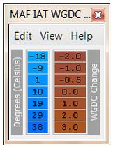
So now we know 3 of the 7 values needed for the MAF IAT WGDC Correction table:
Min Temp: -2.0% (-18*C)
Tuned Temp: 0% (10*C)
Max Temp: +3.0% (38*C)
All thats left is filling in the blanks to make a smooth, linear curve like I did here as an example.Tuned Temp: 0% (10*C)
Max Temp: +3.0% (38*C)
This was way more info than you probably asked for but I hope it helped somewhat lol.
-Jamie
(jack_of_trades)
Last edited by Dynotech Tuning; Apr 12, 2011 at 10:33 AM.
Apr 12, 2011, 11:13 AM
#11
I've attached the OpenOffice (free version of Microsoft Excel) spreadsheet I made to quickly get this info for ya if you want to try it. It should work fine with Excel also. It doesn't matter whether you use Fahrenheit or Celesius.

You can download the speadsheet here:
MAF IAT WGDC Correction Calculator
I hope this helps,
-Jamie
(jack_of_trades)
You can download the speadsheet here:
MAF IAT WGDC Correction Calculator
I hope this helps,
-Jamie
(jack_of_trades)
Last edited by Dynotech Tuning; Apr 12, 2011 at 11:18 AM.
 Apr 12, 2011, 04:26 PM
#13
I think what he was saying is to zero out the "Max Total Upward WGDC Correction vs TPS"
If you do that, the error correction will still be able to *add* back in WGDC up to *base WGDC* and never above.
Apr 12, 2011, 04:31 PM
#14
I wouldn't set the Error Correction table like that, if it takes 5% out then it will never add it back since you have the upward correction zeroed out 5+
I think what he was saying is to zero out the "Max Total Upward WGDC Correction vs TPS"
If you do that, the error correction will still be able to *add* back in WGDC up to *base WGDC* and never above.
I think what he was saying is to zero out the "Max Total Upward WGDC Correction vs TPS"
If you do that, the error correction will still be able to *add* back in WGDC up to *base WGDC* and never above.

Thread
Thread Starter
Forum
Replies
Last Post
[WTB] Fp black MHI housing
Tmosser
For Sale/WTB - Engine / Drivetrain / Power
0
Jul 20, 2016 05:01 PM
TurboTom107
Evo Engine / Turbo / Drivetrain
10
Jan 18, 2014 06:03 PM
hiimwayne
Evo Engine / Turbo / Drivetrain
1
Nov 17, 2009 09:55 PM