Dissecting and analyzing the clutch master and slave cylinder (photo intensive)
 May 26, 2012, 06:55 PM
#1
Evolving Member
Thread Starter
iTrader: (1)

Join Date: Aug 2007
Location: Edmonton, Alberta, Canada
Posts: 412
Likes: 0
Received 0 Likes
on
0 Posts
Dissecting and analyzing the clutch master and slave cylinder (photo intensive)
This thread is meant to show the mechanics and structure of the clutch master cylinder and slave cylinder, and reveal possible faults with the design and where issues can arise from failure of said parts.
First of all I will say that I'm no expert, although I am an Engineering Technologist in Training (Civil). If anyone fines anything odd about what I say please let me know and I will think it over or try to explain it better or correct any theories.
On to the dissection. We will start with the slave cylinder, it's simple enough.
Here we have our standard issue Slave Cylinder

First we will remove the boot and rod/pin

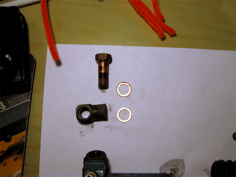
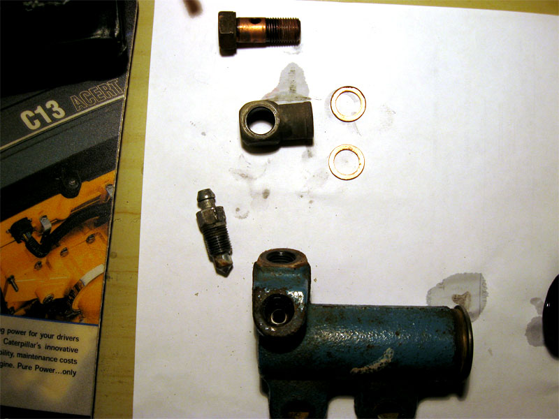
Next we will remove the banjo, banjo bolt, and banjo washers. The banjo is ferrous; the banjo bolt is also ferrous although it appears to be copper, it is copper plated; the two washers are copper.
Next comes the bleeder screw, also ferrous
Out comes the piston and spring. The piston is made from red anodized aluminum. The spring is made from ferrous metal

First of all I will say that I'm no expert, although I am an Engineering Technologist in Training (Civil). If anyone fines anything odd about what I say please let me know and I will think it over or try to explain it better or correct any theories.
On to the dissection. We will start with the slave cylinder, it's simple enough.
Here we have our standard issue Slave Cylinder
First we will remove the boot and rod/pin
Next we will remove the banjo, banjo bolt, and banjo washers. The banjo is ferrous; the banjo bolt is also ferrous although it appears to be copper, it is copper plated; the two washers are copper.
Next comes the bleeder screw, also ferrous
Out comes the piston and spring. The piston is made from red anodized aluminum. The spring is made from ferrous metal
 May 26, 2012, 06:56 PM
#2
Evolving Member
Thread Starter
iTrader: (1)
Join Date: Aug 2007
Location: Edmonton, Alberta, Canada
Posts: 412
Likes: 0
Received 0 Likes
on
0 Posts
Here is a close-up with the piston and seal

Here is a close-up of the seal itself, there are no apparent nicks or cuts of the seal that would cause failure. Also note the mushroom shape of the seal. Much like how combustion gasses of the piston of an engine help to press the back of the piston ring in to the cylinder wall of the piston to help seal it, in this case fluid pressure presses the seal against the wall of the cylinder to help it seal

This is a picture of the bore of the cylinder, this picture doesn't show the bottom (right side when mounted) of the cylinder well

This picture I tried to highlight the inlet and bleed ports of the cylinder

Analyzing the inlet and outlet locations" although it appears the location of the inlet, from the other pictures, is directly vertical, the fluid actually comes out from the back side of the cylinder, and the bleed port is directly on top (which is good), the only thing I would change though is to make the bleed port come out from the back edge of the cylinder instead of a few mm in front of the back wall. That way any trapped air between the back wall and the bleeder screw would be forced out with the travel of the piston instead of being trapped in a dead space.

From these I can say that I personally have no problems with this design. Despite the bleed port not being against the wall, tapping the cylinder would easily enough encourage any trapped air to move to the very close bleed port to be expelled.
Here is a close-up of the seal itself, there are no apparent nicks or cuts of the seal that would cause failure. Also note the mushroom shape of the seal. Much like how combustion gasses of the piston of an engine help to press the back of the piston ring in to the cylinder wall of the piston to help seal it, in this case fluid pressure presses the seal against the wall of the cylinder to help it seal
This is a picture of the bore of the cylinder, this picture doesn't show the bottom (right side when mounted) of the cylinder well
This picture I tried to highlight the inlet and bleed ports of the cylinder
Analyzing the inlet and outlet locations" although it appears the location of the inlet, from the other pictures, is directly vertical, the fluid actually comes out from the back side of the cylinder, and the bleed port is directly on top (which is good), the only thing I would change though is to make the bleed port come out from the back edge of the cylinder instead of a few mm in front of the back wall. That way any trapped air between the back wall and the bleeder screw would be forced out with the travel of the piston instead of being trapped in a dead space.
From these I can say that I personally have no problems with this design. Despite the bleed port not being against the wall, tapping the cylinder would easily enough encourage any trapped air to move to the very close bleed port to be expelled.
Last edited by Canada_Comp; May 26, 2012 at 07:18 PM.
May 26, 2012, 06:56 PM
#3
Evolving Member
Thread Starter
iTrader: (1)
Join Date: Aug 2007
Location: Edmonton, Alberta, Canada
Posts: 412
Likes: 0
Received 0 Likes
on
0 Posts
Master Cylinder
Now moving on to the master cylinder
Here we have our standard issue Clutch Master cylinder. Notice the "silly little plate" as I like to call it, on the cylinder. I believe this has to do with the clutch orifice that many people have and is supposed to help in some way to soften the engagement or help the orifice do it's job. I honestly can't see how this does anything since there isn't any travel on the the parts under the plate.

First we will remove the retaining pin, inlet nipple, and seal
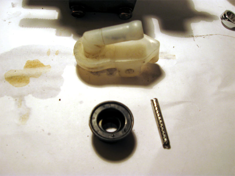
Here is a view of the top once the nipple and seal are removed. I don't know the reason for the blind hole. Perhaps it is for alignment during the manufacturing process

Bleeder screw removed

Then moving on to the piston rod
Here we have our standard issue Clutch Master cylinder. Notice the "silly little plate" as I like to call it, on the cylinder. I believe this has to do with the clutch orifice that many people have and is supposed to help in some way to soften the engagement or help the orifice do it's job. I honestly can't see how this does anything since there isn't any travel on the the parts under the plate.
First we will remove the retaining pin, inlet nipple, and seal
Here is a view of the top once the nipple and seal are removed. I don't know the reason for the blind hole. Perhaps it is for alignment during the manufacturing process
Bleeder screw removed
Then moving on to the piston rod
Last edited by Canada_Comp; May 26, 2012 at 08:20 PM.
May 26, 2012, 06:57 PM
#4
Evolving Member
Thread Starter
iTrader: (1)
Join Date: Aug 2007
Location: Edmonton, Alberta, Canada
Posts: 412
Likes: 0
Received 0 Likes
on
0 Posts
The piston popped out from the spring pressure behind it since the retainer and rod were removed. Notice the ridges on the piston. I believe these are to strengthen and reinforce the piston, which is good, but air can get trapped under the piston if it is in that position....

Here is the piston assembly removed. Note that there are two seals. The fluid from the inlet comes down between those two seals and in to the area where the ridged section exists, with this it should be easy to see how air can get trapped underneath the ridges. Pretend we are bleeding the clutch for a moment, once the fluid is in this area, pressing down the clutch will move the piston to the end of the cylinder. Opening the bleed screw will let fluid out (air is a fluid by the way). Closing the bleeder, then releasing the clutch pedal will create a vacuum on the far right side of the piston pictured. If you remember from the slave cylinder dissection above, the seal is mushroomed, and will essentially act as a one way valve allowing fluid in to the vacuum area past the seal

Next we will remove the "silly little plate"

If you refer to https://www.evolutionm.net/forums/04...l#post10187547 , something from one of these seals is likely the culprit for the black crud.

And yes it is definitely black....

Here is the piston assembly removed. Note that there are two seals. The fluid from the inlet comes down between those two seals and in to the area where the ridged section exists, with this it should be easy to see how air can get trapped underneath the ridges. Pretend we are bleeding the clutch for a moment, once the fluid is in this area, pressing down the clutch will move the piston to the end of the cylinder. Opening the bleed screw will let fluid out (air is a fluid by the way). Closing the bleeder, then releasing the clutch pedal will create a vacuum on the far right side of the piston pictured. If you remember from the slave cylinder dissection above, the seal is mushroomed, and will essentially act as a one way valve allowing fluid in to the vacuum area past the seal
Next we will remove the "silly little plate"
If you refer to https://www.evolutionm.net/forums/04...l#post10187547 , something from one of these seals is likely the culprit for the black crud.
And yes it is definitely black....
Last edited by Canada_Comp; May 26, 2012 at 08:34 PM.
May 26, 2012, 06:57 PM
#5
Evolving Member
Thread Starter
iTrader: (1)
Join Date: Aug 2007
Location: Edmonton, Alberta, Canada
Posts: 412
Likes: 0
Received 0 Likes
on
0 Posts
After cleaning the crud off we have this disc revealed. Just for reference there was a ring underneath the plate that was removed in the previous picture.

Removing the disc, guess what was underneath?

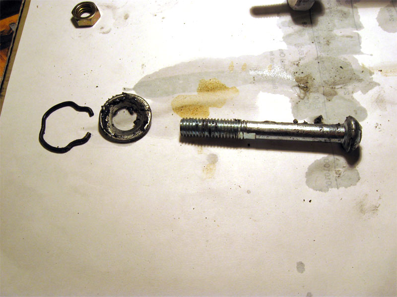
Here is a picture of the gasket that GearDownSon was having a problem with (refer to https://www.evolutionm.net/forums/04...f-problem.html)

Here is the ring I was talking about. At first I thought it was a spring of some sort.

Notice that there is a bend gap, just like a lock washer. This is why I thought it was a spring of some sort for the plate to move back and forward

Removing the disc, guess what was underneath?
Here is a picture of the gasket that GearDownSon was having a problem with (refer to https://www.evolutionm.net/forums/04...f-problem.html)
Here is the ring I was talking about. At first I thought it was a spring of some sort.
Notice that there is a bend gap, just like a lock washer. This is why I thought it was a spring of some sort for the plate to move back and forward
Last edited by Canada_Comp; May 26, 2012 at 08:47 PM.
May 26, 2012, 06:58 PM
#6
Evolving Member
Thread Starter
iTrader: (1)
Join Date: Aug 2007
Location: Edmonton, Alberta, Canada
Posts: 412
Likes: 0
Received 0 Likes
on
0 Posts
This is the disc that was under the ring, which was under the plate.

Here is the seal that was under the disc, which was under the ring, which was under the plate, which was on my MC, which was in my car, which is in Alberta, which is in Canada, which is in North America, which is.....

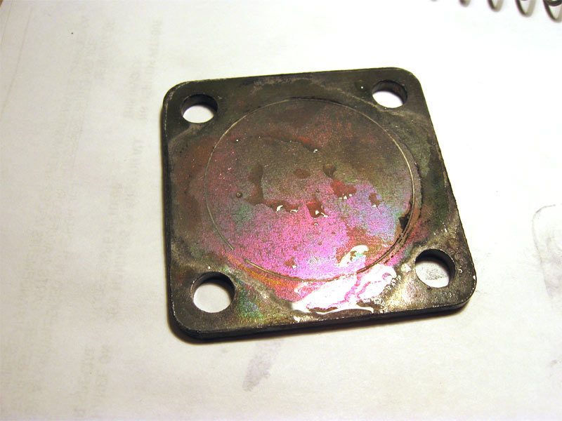
Here is a picture of that plate, notice the scoring from the ring.
This is a picture of the master cylinder body, plate area. A few issues with this, the hole isn't right at the top, which can trap air. Also, there is no pathway for the fluid to flow! Dead space for air to get trapped and making bleeding take forever. I will discuss my theory on bleeding this area below. Also I should mention that with everything put together under the plate (seal, disc, ring, gasket, plate) there is no room for the disc to move. The plate presses the ring against the disc which compresses the seal. There is no room for movement
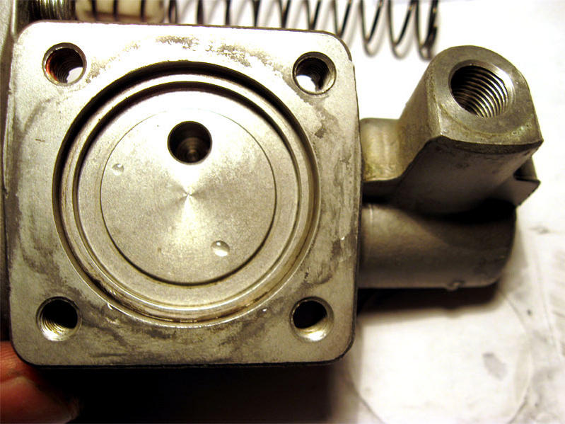
Another shot of the MC body, showing the outlet port

Here is the seal that was under the disc, which was under the ring, which was under the plate, which was on my MC, which was in my car, which is in Alberta, which is in Canada, which is in North America, which is.....
Here is a picture of that plate, notice the scoring from the ring.
This is a picture of the master cylinder body, plate area. A few issues with this, the hole isn't right at the top, which can trap air. Also, there is no pathway for the fluid to flow! Dead space for air to get trapped and making bleeding take forever. I will discuss my theory on bleeding this area below. Also I should mention that with everything put together under the plate (seal, disc, ring, gasket, plate) there is no room for the disc to move. The plate presses the ring against the disc which compresses the seal. There is no room for movement
Another shot of the MC body, showing the outlet port
Last edited by Canada_Comp; May 26, 2012 at 08:57 PM.
May 26, 2012, 06:58 PM
#7
Evolving Member
Thread Starter
iTrader: (1)
Join Date: Aug 2007
Location: Edmonton, Alberta, Canada
Posts: 412
Likes: 0
Received 0 Likes
on
0 Posts
In this picture I tried to highlight the pathway from the bleed screw, which is connected to the outlet port, and plate area, if you can see the light.

Here is a diagram with the pathways, lines that are on top of each other do intersect

As you can see, there are two long bores in the MC. There is the main bore with the piston in it, and the bore which leads to the plate from the bleeder screw, connected via the outlet port. My theory on the fluid flow which bleeds the plate area is that applying the clutch pedal will compress the air in the plate chamber, while some fluid is able to flow in to the chamber. Since fluid has more mass, it moves to the bottom of the chamber while the air moves to the top. Opening the bleeder screw will shoot the air out of the chamber since it is compressed. Not a very good design I would say... what is the purpose of the plate even? It doesn't move (okay, if the seal compresses more it will move), but other than that I only see it as a chamber for air to compress to make the clutch pedal soft initially.
In terms of the cylinder bore, there is a large dead space since the outlet port/bleeder isn't at the very end of the cylinder bore, this can make bleeding difficult since it's not at the end and can trap air.
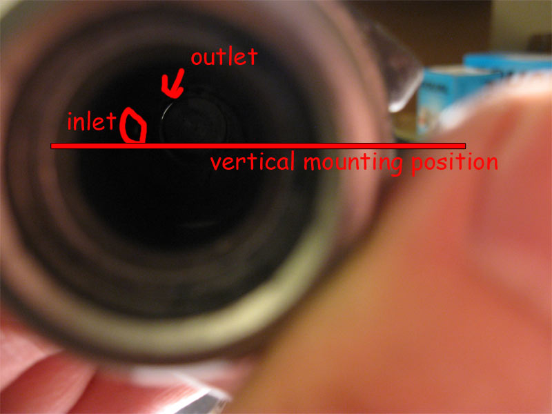
This picture shows the inlet port in the cylinder. The vertical mounting position reference is shown. The inlet is directly on top of the cylinder, making it ideal to bleed if you are using the reverse bleed method

This picture shows the outlet in the cylinder bore. Aside from not being at the back, it is slightly off center towards the driver's right side when mounted
This picture shows the piston position relative to the cylinder at full depression.
note how the seal does not go all the way to the back. Understandable since there has to be room for the spring, but how come the spring couldn't be in the center of the piston (like the slave piston is) so that the seal could be all the way back? Also note the piston ridges that can trap air underneath

Here is a diagram with the pathways, lines that are on top of each other do intersect
As you can see, there are two long bores in the MC. There is the main bore with the piston in it, and the bore which leads to the plate from the bleeder screw, connected via the outlet port. My theory on the fluid flow which bleeds the plate area is that applying the clutch pedal will compress the air in the plate chamber, while some fluid is able to flow in to the chamber. Since fluid has more mass, it moves to the bottom of the chamber while the air moves to the top. Opening the bleeder screw will shoot the air out of the chamber since it is compressed. Not a very good design I would say... what is the purpose of the plate even? It doesn't move (okay, if the seal compresses more it will move), but other than that I only see it as a chamber for air to compress to make the clutch pedal soft initially.
In terms of the cylinder bore, there is a large dead space since the outlet port/bleeder isn't at the very end of the cylinder bore, this can make bleeding difficult since it's not at the end and can trap air.
This picture shows the inlet port in the cylinder. The vertical mounting position reference is shown. The inlet is directly on top of the cylinder, making it ideal to bleed if you are using the reverse bleed method
This picture shows the outlet in the cylinder bore. Aside from not being at the back, it is slightly off center towards the driver's right side when mounted
This picture shows the piston position relative to the cylinder at full depression.
note how the seal does not go all the way to the back. Understandable since there has to be room for the spring, but how come the spring couldn't be in the center of the piston (like the slave piston is) so that the seal could be all the way back? Also note the piston ridges that can trap air underneath
Last edited by Canada_Comp; May 26, 2012 at 09:15 PM.
Trending Topics
May 26, 2012, 06:59 PM
#8
Evolving Member
Thread Starter
iTrader: (1)
Join Date: Aug 2007
Location: Edmonton, Alberta, Canada
Posts: 412
Likes: 0
Received 0 Likes
on
0 Posts
In summary:
The slave cylinder has no apparent problems other than the minor detail that the bleeder port is a few mm from the back wall of the cylinder.
The master cylinder had many faults. The plate that leads to nowhere and would be super hard to bleed completely, the ridges on the piston trapping air, the dead space at the end of the cylinder bore, the outlet of the bore being offset from top.
With these, I would say the best position for the car to be in to bleed would be facing down hill with the passenger side of the car elevated slightly to make the air in the MC move against the piston and towards the outlet port side. That way, air can be eliminated from the dead space at the end of the cylinder bore since it is against the piston. This position probably wouldn't help the "silly little plate" though.
End Dissection
Last edited by Canada_Comp; May 26, 2012 at 09:37 PM.
May 27, 2012, 08:30 AM
#10
Just excellent. Thank you!
Hmm, maybe the plate acts as a spring and deflects when you use the clutch, and the deflection uses up some of your input force and thus "softens" the feel. Its a pretty big area, and thus there would be a large force pushing on it so it would bend (force=pressure x area).
Hmm, maybe the plate acts as a spring and deflects when you use the clutch, and the deflection uses up some of your input force and thus "softens" the feel. Its a pretty big area, and thus there would be a large force pushing on it so it would bend (force=pressure x area).

 May 27, 2012, 09:30 AM
#12
Evolving Member
Thread Starter
iTrader: (1)
Join Date: Aug 2007
Location: Edmonton, Alberta, Canada
Posts: 412
Likes: 0
Received 0 Likes
on
0 Posts
Just excellent. Thank you!
Hmm, maybe the plate acts as a spring and deflects when you use the clutch, and the deflection uses up some of your input force and thus "softens" the feel. Its a pretty big area, and thus there would be a large force pushing on it so it would bend (force=pressure x area).
Hmm, maybe the plate acts as a spring and deflects when you use the clutch, and the deflection uses up some of your input force and thus "softens" the feel. Its a pretty big area, and thus there would be a large force pushing on it so it would bend (force=pressure x area).
May 28, 2012, 06:37 PM
#13
Evolving Member
iTrader: (1)

Join Date: Sep 2009
Location: Sherbrooke, QC
Posts: 349
Likes: 0
Received 0 Likes
on
0 Posts
My slave failed, and I ran to a local scrapyard and got this off a 4cyl MX-6, the cylinders looked alike and had the same exact bore. It fits perfectly inside my slave cylinder, and seems better built then ours. (It has a second o-ring on the piston) I don't think the 1/4 inch difference in piston lenght will change anything, and if so, I have the MX-6 rod to try on also. Also note that the shorter piston has a shallower hole inside it, the longer, the deepest.
Just something I thought you might have found interesting...

Just something I thought you might have found interesting...
Last edited by xmaster19; May 28, 2012 at 06:42 PM.
May 28, 2012, 10:10 PM
#14
Evolving Member
Thread Starter
iTrader: (1)
Join Date: Aug 2007
Location: Edmonton, Alberta, Canada
Posts: 412
Likes: 0
Received 0 Likes
on
0 Posts
My slave failed, and I ran to a local scrapyard and got this off a 4cyl MX-6, the cylinders looked alike and had the same exact bore. It fits perfectly inside my slave cylinder, and seems better built then ours. (It has a second o-ring on the piston) I don't think the 1/4 inch difference in piston lenght will change anything, and if so, I have the MX-6 rod to try on also. Also note that the shorter piston has a shallower hole inside it, the longer, the deepest.
Just something I thought you might have found interesting...
Just something I thought you might have found interesting...
 hopefully it's a good solution for those of us looking for something more reliable