
Speed Density 2.0?


i am happy to be a tester for 9653... plus it might give me motivation to start fiddling with livemap app again 
with a good map tracer you should be able to filter out data like when STFT is not 0... or inj=0 tps etc. i think dataloglab was able to do something similar
with a good map tracer you should be able to filter out data like when STFT is not 0... or inj=0 tps etc. i think dataloglab was able to do something similar
I've decided to give the coding a shot on my own. Here is a screen shot of the tables I plan to use. I have them fully incorporated into the code and could probably alpha test it tomorrow, although I am out of time this weekend and it will have to wait.


Interested in seeing your results.
Funny thing is acamus had a 3D VE table ready for probably a year or so ... I just never had time to test it.
I looked through my old ROMs and this is one that I was setting up to test:

One suggestion may be to your RPM on the vertical axis, since we are used to that in most of our main 3D maps. But that's just a preference.
Just posting up to show a comparison of what you did compared to him. This was my 'base' VE table that I was going to flash in to start tuning. Since I just started running SD again a few days ago, I will probably multiply out my current 2D tables to get my new 3D table for a good starting point. My SD tune seems to be spot on, so it should be a simple swap. Then the 3D table can be able to fine tune certain map/RPM areas a lot better (by analyzing the STFT behavior in those areas of the logs).
Funny thing is acamus had a 3D VE table ready for probably a year or so
... I just never had time to test it.I looked through my old ROMs and this is one that I was setting up to test:
One suggestion may be to your RPM on the vertical axis, since we are used to that in most of our main 3D maps. But that's just a preference.
Just posting up to show a comparison of what you did compared to him. This was my 'base' VE table that I was going to flash in to start tuning. Since I just started running SD again a few days ago, I will probably multiply out my current 2D tables to get my new 3D table for a good starting point. My SD tune seems to be spot on, so it should be a simple swap. Then the 3D table can be able to fine tune certain map/RPM areas a lot better (by analyzing the STFT behavior in those areas of the logs).
I think the 3D table with the startup baro option and MAT startup fix should make SD perfect. It already is pretty damn good and this was just the first try by jcsbanks way back when.
It's nice to see progress like this from the community.
So forgive me for not reading the thread again, but what are the planned changes for SD 2.0...I think getting a list would be nice:
1. 3D VE table
2. Ability to use an extra baro sensor at startup, for starting at different altitudes
3. Ability to use a different MAT temperature for startup, to prevent lean starting with heat soaked MAT sensors
Eric
It's nice to see progress like this from the community.
So forgive me for not reading the thread again, but what are the planned changes for SD 2.0...I think getting a list would be nice:
1. 3D VE table
2. Ability to use an extra baro sensor at startup, for starting at different altitudes
3. Ability to use a different MAT temperature for startup, to prevent lean starting with heat soaked MAT sensors
- I would suggest a configurable MAT temp subtraction from measured MAT temp
- Configurable coolant temp above which correction occurs
- Possibly a configurable decay rate or hold time for the corrected MAT temp.
Eric
Last edited by l2r99gst; Aug 28, 2010 at 07:28 AM.
I may have different plans then what others are looking for.
I would like to address the start up issues (both hot and low baro), but I'm not real sure how the startup stuff works, so it's above my pay grade.
I would like to address the start up issues (both hot and low baro), but I'm not real sure how the startup stuff works, so it's above my pay grade.
Stock MDP?
I wrote up a spread sheet to toss in some trial values to see if it works out and everything looks solid. Still debating if I want to use the 8-point MAP scaling table or go to a multiplier and adder setup. The table lookup is probably more intuitive, but it adds unneeded redundancy as 99.9% of MAP sensors are linear.
I wrote up a spread sheet to toss in some trial values to see if it works out and everything looks solid. Still debating if I want to use the 8-point MAP scaling table or go to a multiplier and adder setup. The table lookup is probably more intuitive, but it adds unneeded redundancy as 99.9% of MAP sensors are linear.

Evolving Member
Joined: Apr 2008
Posts: 265
Likes: 1
From: Reading, PA
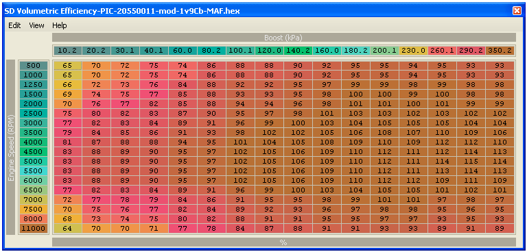
Here is the "SD 2.0" VE% map I have been using on the H8 DSMs.
Below is a tuned map for E3 16G on a 2.0 low compression motor running mid 20s for boost.
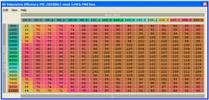
03whitegsr, that huge VE% map is going to be a pain/impossible to tune. Even a 18x16 sized map like mine takes a while to make from scratch.
l2r99gst, I started with a map like yours, but found there needs to be more resolution at higher boost.
Below is a tuned map for E3 16G on a 2.0 low compression motor running mid 20s for boost.
03whitegsr, that huge VE% map is going to be a pain/impossible to tune. Even a 18x16 sized map like mine takes a while to make from scratch.
l2r99gst, I started with a map like yours, but found there needs to be more resolution at higher boost.
Only reason I made it that size is because of people constantly insisting on the Big Maps being better.
I personally prefer reasonable size maps as well. I'm just making it large for a place holder in the memory.
I personally prefer reasonable size maps as well. I'm just making it large for a place holder in the memory.

Evolving Member
Joined: Jul 2009
Posts: 274
Likes: 0
From: MA
Pretty exciting stuff ! Looking at those tables conceptually makes a ton more sense to me than the MAP Kpa/ load +RPM/ VE tables even if tuning might be a little more involved.
Last edited by 95630706; Aug 28, 2010 at 07:30 PM.