
Maxing out the Evo 10 MAF?

No, I understand. I've tuned enough of these to know that the curve changes with each intake.
Some MAF Scalings actually lower in the low voltages and rise in the upper voltages. Others raise linearly in the lower voltages, but increase a lot in the upper range.
What you are doing is a good start, but some long term logging with some proper trim based maf scaling is in order. I usually tweak the upper voltage ranges some based off WOT pulls.


yeah i have trouble with this concept as well.
a 3.5" tube is almost 2x the cross sectional area of a 2.5" tube.
So the theory is the table should be multiplied by 2... But that doesn't work for some reason, you get values WAY to large...
The best thing todo is get a number of sample points (idle, 2000 cruise, 3500 cruise), get the STFT/LTFT trim change and then use that as the multiplier for the MAF..
Then interpolate the voltages in between by the same rough amount...
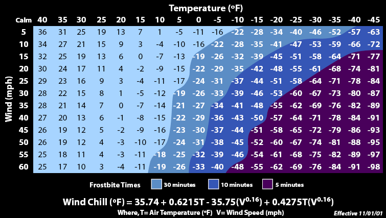
It's because we use a hotwire maf. Windchill is a squareroot type equation in relation to velocity. So doubling the air speed does not double the windchill. The voltage does not decrease linearly.
See table:
See table:
but with a larger intake the airspeed is actually less..
so you are saying that
2.5 -> 3.5 is a 2x increase in area.
but we need to sq rt that to get the new cooling affect
ie going from 2.5 -> 3.5 is a gain of 40% (140%)
so you are saying that
2.5 -> 3.5 is a 2x increase in area.
but we need to sq rt that to get the new cooling affect
ie going from 2.5 -> 3.5 is a gain of 40% (140%)
Yes, but it is velocity based. I don't know what a good equation would be. We change MAF size and the MAF outputs different volts than it used to. Even looking at the stock MAF scaling, you can see that volts to airflow is not a linear graph.
It is much easier to empirically determine the air flow from current MAF Voltages than to try to come up with a flat equation. There are spread sheets out there that really help with this. I use a custom one that makes sure that STFT are != 0 for the calculations, because that usually means that we are not in closed loop. That will work for the 2.66 volts and less area. From there you have to guess at the high end. Here I like to run the car at WOT and see what the AFR is. I then scale it to get the AFR back to what it was with the stock MAF. I basically end up doing the same type calculations the fuel trims do at low voltages. Finally I smooth the line out.
It is much easier to empirically determine the air flow from current MAF Voltages than to try to come up with a flat equation. There are spread sheets out there that really help with this. I use a custom one that makes sure that STFT are != 0 for the calculations, because that usually means that we are not in closed loop. That will work for the 2.66 volts and less area. From there you have to guess at the high end. Here I like to run the car at WOT and see what the AFR is. I then scale it to get the AFR back to what it was with the stock MAF. I basically end up doing the same type calculations the fuel trims do at low voltages. Finally I smooth the line out.

thats basically exactly right B, we dont really know what the values mean.
well we do - I looked it up a couple of days ago...
I will post up how these numbers get converted into load in a little bit.
Then maybe someone can reverse engineer them to go back to something meaningful..
well we do - I looked it up a couple of days ago...
I will post up how these numbers get converted into load in a little bit.
Then maybe someone can reverse engineer them to go back to something meaningful..
I think I can make a spread sheet that will calculate new MAF tables based on airflow changes. Now this won't account for eddy currents and flow characteristics of the new intake, but it can be used as a much better rough estimate when slapping on a new intake.
Also, I thought the stock MAF was closer to 2.83 when measured at MAF's location. Maybe I'm thinking of something else. I'll measure it tonight.
Also, I thought the stock MAF was closer to 2.83 when measured at MAF's location. Maybe I'm thinking of something else. I'll measure it tonight.
Thread Starter
EvoM Guru
iTrader: (50)
Joined: Mar 2006
Posts: 9,675
Likes: 132
From: Tri-Cities, WA // Portland, OR
m = [(aftermarket maf tube inside diameter)/(stock maf tube inside diameter)]^2
where the diameter is measured at the location of the MAF wire.
Last edited by mrfred; Mar 19, 2011 at 08:58 AM.
Thread Starter
EvoM Guru
iTrader: (50)
Joined: Mar 2006
Posts: 9,675
Likes: 132
From: Tri-Cities, WA // Portland, OR
putting it to the test
I had 3dman1 measure the ID of the stock maf tube and the Primo. Stock is 2.72" ID at the MAF wire, and Primo is 3.32". Using my formula:
m=(3.32/2.72)^2=1.49
In my dialing in of the Primo, I started with about 1.8 because I didn't have the MAF tube measurements, and I assumed the stock tube was more like 2.6" and the Primo was more like 3.5". I ended up with 1.5 to get the cruise trim and WOT AFRs spot on with where they were with the stock MAF tube, so there ya go.
I will need to tweak the calibration slightly in the idle range, but not surprising.
Last edited by mrfred; Mar 19, 2011 at 09:45 AM.
Where are you guys getting your diameter squared stuff from?
The area of a circle is pi * radius ^2 or pi * ( diameter / 2 ) ^2
And I don't understand why you would take the square root of the ratio of diameters.
The area of a circle is pi * radius ^2 or pi * ( diameter / 2 ) ^2
And I don't understand why you would take the square root of the ratio of diameters.
Thread Starter
EvoM Guru
iTrader: (50)
Joined: Mar 2006
Posts: 9,675
Likes: 132
From: Tri-Cities, WA // Portland, OR
Diameter or radius is fine when taking the ratio of the MAF tube cross sectional areas. Radius is 1/2 the diameter, so when taking the ratio of tube size using the diameter, the factor of 1/2 cancels out from top and bottom.