
Narrowband Output Graph

Thread Starter
Evolved Member
iTrader: (26)
Joined: Nov 2005
Posts: 717
Likes: 0
From: San Diego, CA
Narrowband Output Graph
http://www.zeitronix.com/questions/NBpoint.htm
I remember having a chat with some peeps on how to get better mileage and still utilize the closed loop operation of the ECU. The Zeitronix can do it fairly easily. I have a PLX R-500 and it's a bit tougher. I have a configurable wideband output graph where I can adjust the voltage at each lambda point. Even though the graph scales to 5v, I'm sure I could still imitate a narrowband graph. So I need to mimic the OEM narrowband output to a T. Does anybody have this graph? Do all narrowbands share this same graph? Does it look like the one below?
http://www.plxdevices.com/AppNotes/PLXApp004.pdf

The PLX simulated output mimics a narrowbands signal curve exactly. All you need to do is keep the stock FRONT O2 sensor installed and hooked up (to plug the front o2 sensor location , keep you from getting any CEL's, and so you won't need to do the resistor mod), either remove the front O2 sensor wire from the ECU harness (pin 71 for evo IX's) and install an evo IX pin (can get them here)on the grey wire from your PLX harness and re-install it into the harness or you can just cut the ecu wire and splice the grey wire to the ecu harness. Be sure to tape off the used front O2 sensor wire.
Then you simply change the narrowband switching point via the PLX display or any PC software available and you either higher or lower voltage until you get the wideband AFR readings in closed loop that you desire. Most guys run around 15.5AFR in closed loop without any issues.
Don't forget to install the supplied filtering capacitor between the gray wire and the ground wire to keep noise to a minimum.
Hope that helps.
Last edited by Jack_of_Trades; May 16, 2008 at 12:01 PM.
Yeah, I've heard that you can. The Zeitronix software converts its from an AFR setting so all I have to type in is the desired AFR switching point but I'm not sure if Innovate uses a voltage switching point or an AFR switching point. If you have to enter in the voltage, just change the voltage and see what the closed loop AFR's settle down at.
I've found that larger cammed cars will want to increase their open loop tables so idle is in open loop at 14.7 or slightly richer for a smoother idle with cams.
I've found that larger cammed cars will want to increase their open loop tables so idle is in open loop at 14.7 or slightly richer for a smoother idle with cams.
Trending Topics
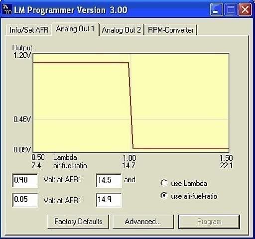
That came from this thread/post ...
http://www.innovatemotorsports.com/f...75&postcount=5
It looks easy enough ... but I honestly haven't touched the LM programmer since I installed the sensor.
Last edited by TouringBubble; May 16, 2008 at 12:52 PM.
Thread Starter
Evolved Member
iTrader: (26)
Joined: Nov 2005
Posts: 717
Likes: 0
From: San Diego, CA
Jack, I don't see where you found the software option to change the narrowband switching point on either the PLX M-series or R-series? Both have the narrowband 0-1v gray analog output wire though. It just outputs and you can't change the value to my knowledge though. Only the light green wire on the R-500 can be changed.
Last edited by silex; May 16, 2008 at 06:01 PM.
I did it and didn't see a thing as far as mpg increase with my driving mostly highway and a brief stint in the public roads back and forth from work. After awhile my sensor started to go out on me and it nearly left me stranded once going crazy lean lol! I babied it back home and put the old sensor back in that day and have never looked back 
Thread Starter
Evolved Member
iTrader: (26)
Joined: Nov 2005
Posts: 717
Likes: 0
From: San Diego, CA
This method keeps the stock sensor in the proper spot with the connector still attached. You just use the narrowband output from the wideband unit to alter the switching point of the AFR. It sounds like you did a "narrowband replacement" with the wideband o2 sensor.
Yep thats how the zeitronix one works you cut the purple wire up in the ecu harness and patch in the zeitronix simulated narrowband output. So when my wideband sensor started to go a little off the wall i needed to patch it back in.
So you installed the wideband sensor in the O2 housing in place of the front O2 sensor??? Thats wayyyy too close to the turbo for safe operation, temperature wise. A wideband should be at least 16" from the turbo outlet.