


Does the stock fuel pump use a solid state relay?


Here is the diagram.... Its kinda strange:
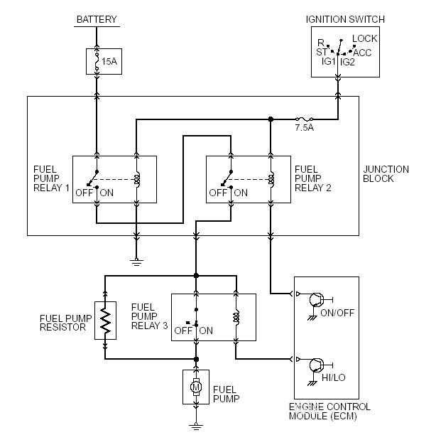
So from what I read it does this:
So from what I read it does this:
When the load on the engine is low, the engine control module (ECM) turns the power transistor ON,which causes the current to flow through the coil ofthe fuel pump relay 3. Accordingly, the contacts ofthe relay open, causing the current to the fuel pumpto flow via the fuel pump resistor. Because the resistor drops the voltage of the current, the supply voltage to the fuel pump decreases. As a result, thepump speed decreases, thus reducing the fuel discharge volume of the fuel pump.
When the load on the engine is higher than the prescribed value, the ECM turns OFF the power transistor, which causes the contacts in fuel pump relay 3 to
close. This eliminates the voltage drop by the resistor. As a result, the pump speed increases, thusincreasing the fuel discharge volume of the fuelpump.
Hope that helps 

You can do it different ways. Most people just use a fuel pump output wire to trigger a relay that feeds the pump high voltage. You could also use the stock or stocklike wiring to give it multiple voltages (High/Low) using a resistor. I havent looked into making it change voltage... I would assume you could use one of the pulsewidth outputs to make whatever voltage you want (Have it 8volts at idle and the more boost = more voltage) and once you hit x (Say around 20psi) have it use another switch to give it the highest voltage without being pulsewidth but I dunno.

Thread Starter
Evolved Member
iTrader: (2)
Joined: Apr 2004
Posts: 1,940
Likes: 1
From: Milwaukee, WI
Trending Topics

Some of us dont know electronics I dont know what solid state means anyways.
His user 1 answer is referring to what I said is possible... using pulsewidth. I personally would not do it. This is how I would do it if you want to make it high/low voltage:
Run a power wire from the bat -> relay. Use one of the outputs to turn on with the ign (output x -> relay1 open/close pole). Then have a resistor sitting right behind that relay making it low voltage. Then jumper the power wire from right in front of that relay to another relay (After the resistor) and use output x2 -> relay2 open/close. That way under normal curcumstances it will go through the first relay because the second relay is not open. When voltage goes through the first relay it will be forced through the resistor. When you set your parameters to use output x2 (Like at 10psi load) it will open the second relay causing the power to go straight from the battery to the fuel pump and will bypass the resistor.
That is how i would do it... you may even be able to use the stock wiring... it seemed pretty beefy. The stock wiring already has all those relays so all you would need to do is figure out which pins = which stock wiring (The AEM comes with it already done this way).
I dont know what solid state means anyways.His user 1 answer is referring to what I said is possible... using pulsewidth. I personally would not do it. This is how I would do it if you want to make it high/low voltage:
Run a power wire from the bat -> relay. Use one of the outputs to turn on with the ign (output x -> relay1 open/close pole). Then have a resistor sitting right behind that relay making it low voltage. Then jumper the power wire from right in front of that relay to another relay (After the resistor) and use output x2 -> relay2 open/close. That way under normal curcumstances it will go through the first relay because the second relay is not open. When voltage goes through the first relay it will be forced through the resistor. When you set your parameters to use output x2 (Like at 10psi load) it will open the second relay causing the power to go straight from the battery to the fuel pump and will bypass the resistor.
That is how i would do it... you may even be able to use the stock wiring... it seemed pretty beefy. The stock wiring already has all those relays so all you would need to do is figure out which pins = which stock wiring (The AEM comes with it already done this way).
By the way... the pulsewidth options can easily make you a surefire way to control meth.... instead of buying thier wierd little control box you could just set the EMS to use pulsewidth outputs based on load. So at 10psi it craps out X voltage and at higher boost it gives the pump more voltage (Spraying more meth). I should have done it this way instead of buying the meth "kit".
Originally Posted by TrinaBabe
That is how i would do it... you may even be able to use the stock wiring... it seemed pretty beefy. The stock wiring already has all those relays so all you would need to do is figure out which pins = which stock wiring (The AEM comes with it already done this way).
Pin 39 controls the 3rd relay which lowers the voltage to the pump. Also LS #1 in the AEM.

The only thing I can think of from the diagram to make sense of it is that relay 1 is ignition control over the fuel pump, relay 2 is you ECU's control over the fuel pump and relay three is high/low pressure control.
Last edited by fre; May 31, 2007 at 08:06 PM.
