


Dialing in cams with degree wheel and dial guage


Ted, can you review these steps? I've never done this before but have done a good amount of reading on engine building. My goal is to simply help my friend get his Buschur head and shortblock put together properly.
1. Before you bolt the head on, use the dial guage to find TDC
2. Bolt the head on lining up the cams with the factory timing marks
3. Install the timing belt.
4. Attach the degree wheel to the crank pulley
5. Create a reference point for the degree wheel. Take note of what TDC is.
6. Put follower of dial guage on intake came lobe for cyl1
7. Find lobe centerline (center of dwell at peak lift)
8. Take note of degrees ATDC
9. Compensate for deviation from cam manufacturer spec with cam gears
Then repeate for exhaust cam except its measured in degrees BTDC?
Am I making any sense? Sorry I have never done this before.
1. Before you bolt the head on, use the dial guage to find TDC
2. Bolt the head on lining up the cams with the factory timing marks
3. Install the timing belt.
4. Attach the degree wheel to the crank pulley
5. Create a reference point for the degree wheel. Take note of what TDC is.
6. Put follower of dial guage on intake came lobe for cyl1
7. Find lobe centerline (center of dwell at peak lift)
8. Take note of degrees ATDC
9. Compensate for deviation from cam manufacturer spec with cam gears
Then repeate for exhaust cam except its measured in degrees BTDC?
Am I making any sense?
Sorry I have never done this before.you can do all this with the cylinder head on, as long as your indicator has the reach to do so.
1. install the degree wheel onto the front of the crankshaft. situate the degree wheel in a way that is easy to read, basically 0 being in a readable position. tighten the fastening bolt down so the wheel doesnt spin.
2. make a wire pointer with a fine tip. be sure you can slip your belt on without having to move your pointer.
3. bring the piston to a visual tdc, adjust your point.
4. install your dial indicator on top of the piston, i put the indicator in line with the piston pin to help minimize piston rock. try & use a tip that has a ball on the end.
5. adjust your zero on the indicator, by spining the bottom end. once happy
6. i usually drop the piston ~.100", note the timing, swing it back the other way & drop the piston .100", note the timing.
7. add the 2, split the difference & adjust the pointer. for example. if you got 22deg & 16deg = 38 / 2 = 19. so if you stopped on 16 deg, did your math & now you tweak the pointer to 19 deg.
8. repeat steps 5-7 several times till your confident youve established tdc.
now your ready to put your belt & cylinder head on if you havent done it already.
i find it easier to place my indicator on the retainer top than having it rest on the cam.
then proceed with your steps of 7-9.
have fun


Thread Starter
Evolved Member
Joined: Oct 2002
Posts: 2,788
Likes: 1
Ok I've spent some more time thinking and looking at how to do this. First question I have, is that it seems I should have to use the valve spring retainer to measure lift on the valve because the lobe is facing down at peak lift. Am I right on that point?
Second, is sort of regarding firing order and valve positions. Can someone tell me, when cam gears are lined up with factory timing marks, what stroke is each cylinder in?
Cylinder / Position / Beginning Stroke
1-TDC-power
2-BDC-exhaust
3-BDC-compression
4-TDC-intake
So based on the above, this tells me my steps will be:
1. Attach degree wheel.
2. Find TDC using piston stop method.
3. Ensure crank and cam gears are lined up with factory timing marks.
4. Set degree wheel to zero.
5. Rotate crank 360 degrees so that Cyl-1 is between exhaust and intake stroke.
6. Set dial guage on valve spring retainer of exhaust cam.
7. Rotate crank backwards to find lobe centerline / peak lift of exhaust cam.
8. Note number of crank degrees BTDC we are.
9. If out of spec for cam, change adjustable cam gear to get right.
Is that sequence correct?
Another question, when cam makers give figures for an exhaust cam, for example 110 degrees lobe centerline... is the 110 BTDC mean that after 110 of forward crank rotation you will be at TDC? So you could describe it as negative 110 in terms of TDC correct?
Sorry if I'm being a bit thick, just trying to fully understand things before diving in.
Second, is sort of regarding firing order and valve positions. Can someone tell me, when cam gears are lined up with factory timing marks, what stroke is each cylinder in?
Cylinder / Position / Beginning Stroke
1-TDC-power
2-BDC-exhaust
3-BDC-compression
4-TDC-intake
So based on the above, this tells me my steps will be:
1. Attach degree wheel.
2. Find TDC using piston stop method.
3. Ensure crank and cam gears are lined up with factory timing marks.
4. Set degree wheel to zero.
5. Rotate crank 360 degrees so that Cyl-1 is between exhaust and intake stroke.
6. Set dial guage on valve spring retainer of exhaust cam.
7. Rotate crank backwards to find lobe centerline / peak lift of exhaust cam.
8. Note number of crank degrees BTDC we are.
9. If out of spec for cam, change adjustable cam gear to get right.
Is that sequence correct?
Another question, when cam makers give figures for an exhaust cam, for example 110 degrees lobe centerline... is the 110 BTDC mean that after 110 of forward crank rotation you will be at TDC? So you could describe it as negative 110 in terms of TDC correct?
Sorry if I'm being a bit thick, just trying to fully understand things before diving in.

Thread Starter
Evolved Member
Joined: Oct 2002
Posts: 2,788
Likes: 1
Something else puzzling me... 
Here is the degree wheel I happen to be using:
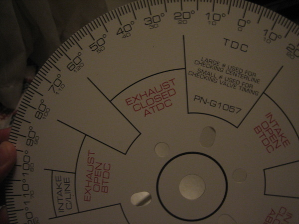
Now this makes sense to me, except the red text 90 degree to the left (BTDC).
Assume we have the wheel setup on the crank pulley, Cyl-1 at TDC between exhaust and intake strokes, and wheel pointer set to zero. We then rotate the crank 100 degrees forward. The pointer then is now to the left of TDC on the wheel, in the area where black text says "Intake C/Line". Great! This makes sense to me as I know I'm on the intake stroke so expect this.
But what confuses me... is beneath the black text it says, "Exhaust Open BTDC". I can't for the life of me figure this out. The exhaust valve is not open obviously when intake is at peak lift. And the what confuses is me more is the red text up top near TDC make sense to me... ie intake opening before exhaust closing = overlap at TDC.
Can someone clear this up for me?
Here is the degree wheel I happen to be using:
Now this makes sense to me, except the red text 90 degree to the left (BTDC).
Assume we have the wheel setup on the crank pulley, Cyl-1 at TDC between exhaust and intake strokes, and wheel pointer set to zero. We then rotate the crank 100 degrees forward. The pointer then is now to the left of TDC on the wheel, in the area where black text says "Intake C/Line". Great! This makes sense to me as I know I'm on the intake stroke so expect this.
But what confuses me... is beneath the black text it says, "Exhaust Open BTDC". I can't for the life of me figure this out. The exhaust valve is not open obviously when intake is at peak lift. And the what confuses is me more is the red text up top near TDC make sense to me... ie intake opening before exhaust closing = overlap at TDC.
Can someone clear this up for me?

Question to self: Does anybody use the Piston Stop method of finding True TDC or is it just us Motorcycle guys that use them? The way WOT posted above is the same way,but with a piston stop it takes alot less time and effort.Good help Abby


The events make sense. You're just forgetting the fact that two complete piston strokes comprise the four cycles of a 4-cycle engine. The exhaust valve is not open when the intake is at peak lift. Those events occur at the same place on the wheel as indicated, but occur 360 degrees apart. Remember, the engine fires on every other stroke, so there is an entire combustion stroke between the closing of the intake valve and the opening of the exhaust valve.
You're confused only because you're reading it as if it were a 2-cycle engine.
Got it?
You're confused only because you're reading it as if it were a 2-cycle engine.
Got it?
There are support groups for this type of mental illness.
That is a perfectly good method of locating true TDC, and making sure your timing marks are correct.
That is a perfectly good method of locating true TDC, and making sure your timing marks are correct.
using a piston stop is fine, as long as you know what your doing / know where your @ when your aproaching your stopping device = dont want to damage the top of your piston inadvertantly.
my piston stop also incorporates a whistle to let you know when your getting close!
my piston stop also incorporates a whistle to let you know when your getting close!
using a piston stop is fine, as long as you know what your doing / know where your @ when your aproaching your stopping device = dont want to damage the top of your piston inadvertantly.
i made my piston stop & it incorporates a whistle to let you know when your getting close
i made my piston stop & it incorporates a whistle to let you know when your getting close
Thread Starter
Evolved Member
Joined: Oct 2002
Posts: 2,788
Likes: 1
The events make sense. You're just forgetting the fact that two complete piston strokes comprise the four cycles of a 4-cycle engine. The exhaust valve is not open when the intake is at peak lift. Those events occur at the same place on the wheel as indicated, but occur 360 degrees apart. Remember, the engine fires on every other stroke, so there is an entire combustion stroke between the closing of the intake valve and the opening of the exhaust valve.
You're confused only because you're reading it as if it were a 2-cycle engine.
Got it?
You're confused only because you're reading it as if it were a 2-cycle engine.
Got it?
Could you answer me one more question? Why on earth do the small degree numbers change from 120 to 50? What is the purpose of the small degree numbers?
Also, just for final confirmation, when you say 110in / 110 ex for cam figures. This always means 110 ex = 110 crankshaft degrees BTDC. And 110 in = 110 crankshaft degrees ATDC. Just double checking.
But there is far more than 360 deg of rotation associated with cam action. For ex, with cams of 280 deg duration and let's say 20 deg of overlap, that works out to 460 deg of events. Last I checked, you can't fit that onto a 360 wheel. 
"Exhaust Open BTDC" takes place at the end of the power stroke. The exhaust valves open just before the intake valve, not the other way around.
The small degree numbers are a matter of convenience when expressing IO, IC, EO, and EC values in their common context (e.g. BTDC, ABDC, etc.).
A 110 deg intake LC would be 110 deg ATDC. A 110 deg exhaust LC would be 110 deg BTDC.
Follow the wheel in this sequence:
TDC Power stroke - Exh Open - Exh LC - Int Open - Exh Closed - Int LC - Int Closed , and then it all starts over again.
"Exhaust Open BTDC" takes place at the end of the power stroke. The exhaust valves open just before the intake valve, not the other way around.
The small degree numbers are a matter of convenience when expressing IO, IC, EO, and EC values in their common context (e.g. BTDC, ABDC, etc.).
A 110 deg intake LC would be 110 deg ATDC. A 110 deg exhaust LC would be 110 deg BTDC.
Follow the wheel in this sequence:
TDC Power stroke - Exh Open - Exh LC - Int Open - Exh Closed - Int LC - Int Closed , and then it all starts over again.
Last edited by Ted B; Aug 16, 2007 at 02:10 PM.
Thread Starter
Evolved Member
Joined: Oct 2002
Posts: 2,788
Likes: 1
Ted thanks for bearing with me you are the best.
I do know there is 720 degrees of unique valve events. I do know there is overlap at TDC between exhaust and intake. I do know that exhaust begins opening before power stroke is over.
But two more questions!
Why are you saying "Exhaust Open" should be expressed as BBDC? Does the exhaust not begin to open approaching TDC (BTDC) on the power stroke?
Why exactly do those small numbers change from 120 -> 50?
Why does anyone reference BDC when measuring anything? Would it not be sufficient to express everything in relation to TDC?
I do know there is 720 degrees of unique valve events. I do know there is overlap at TDC between exhaust and intake. I do know that exhaust begins opening before power stroke is over.
But two more questions!
Why are you saying "Exhaust Open" should be expressed as BBDC? Does the exhaust not begin to open approaching TDC (BTDC) on the power stroke?
Why exactly do those small numbers change from 120 -> 50?
Why does anyone reference BDC when measuring anything? Would it not be sufficient to express everything in relation to TDC?