
Tapping Evo9 thermostat housing for an additional 1/8" NPT coolant temp sensor?


Tapping Evo9 thermostat housing for an additional 1/8" NPT coolant temp sensor?
Looking for input/feedback on what I'm thinking about doing before I start drilling/modifying my thermostat housing (Evo9).
I use my Evo on the track, and a recent overheating issue has convinced me I should have a coolant temperature gauge with a programmable warning light (easy to miss the fact that your OEM temp gauge is pegged when you're hot lapping and/or in traffic on track).
I know it's possible to install a coolant temp sender in the radiator hose with an adapter available from Prosport or Greddy, but I'm not a fan of method for two reasons:
I've also seen this thread on NorCalEvo about making an adapter for a coolant sensor off the little hose between the thermostat housing and the turbo:
http://www.norcalevo.net/threads/555...ensor-adapter?
- but this method involves using a lot of hardware store parts for no good reason, and again more potential for coolant leaks by cutting into that hose.
SO, with all that out of the way, I'm convinced the best way to add an additional coolant temp sensor is to tap the thermostat housing itself.
I realize I could just unscrew the OEM 1/8 NPT sender, which I'm assuming is for the factory temp gauge, and then screw in the 1/8 NPT sender for my aftermarket coolant temp gauge, but I like the idea of having the OEM gauge working as well, just in case the aftermarket gauge loses power, or the aftermarket gauge sender dies while I'm on track.
Okay, on to the pictures/plan.
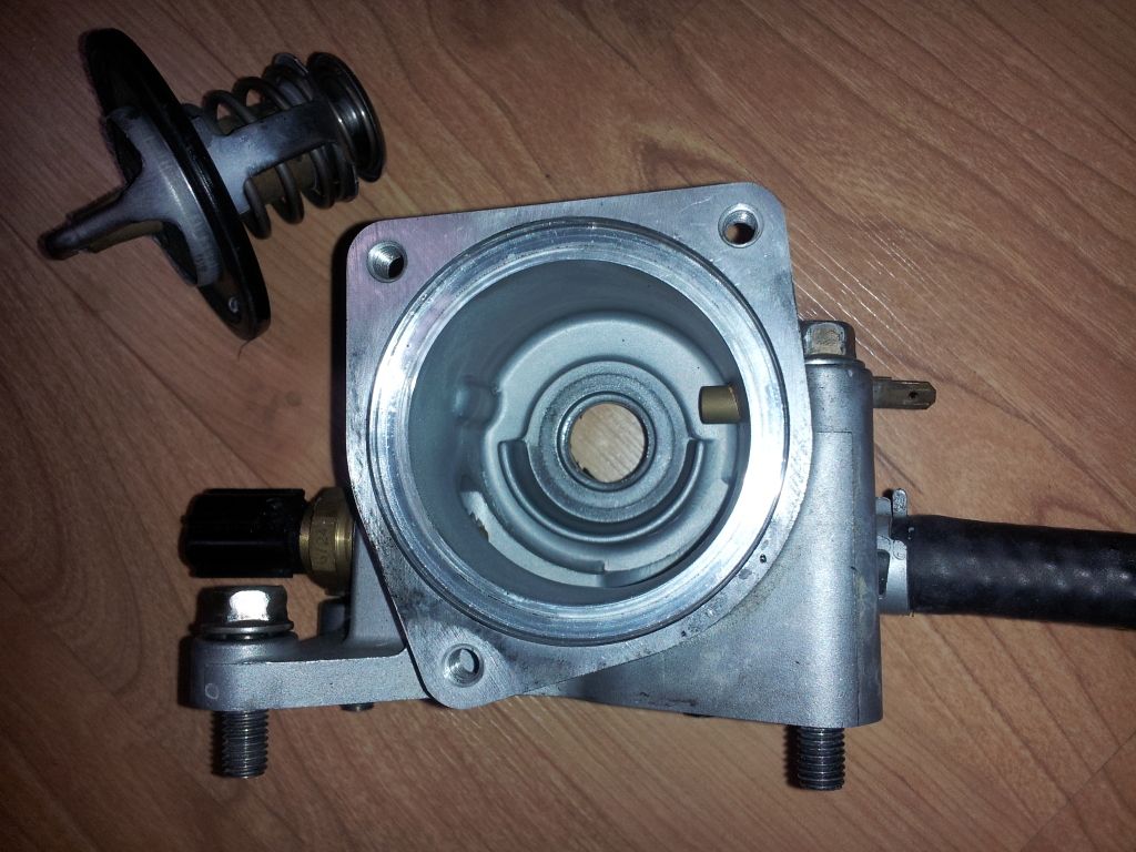
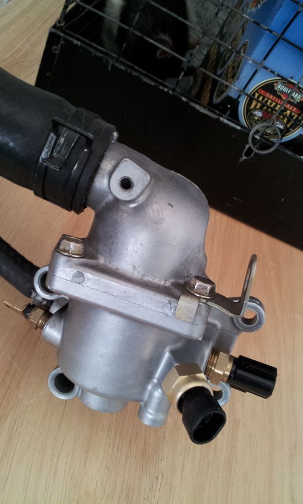
Here's the Evo9 thermostat housing from the top:
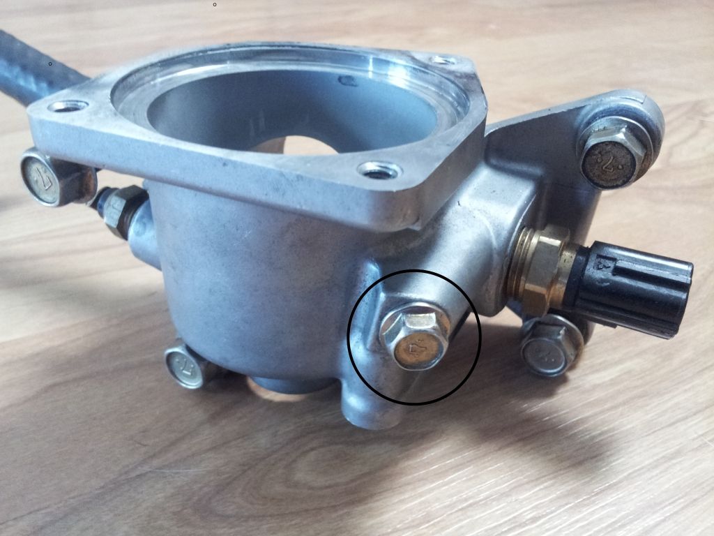
And in this picture, you can see the 10mm-head grounding point bolt that I'm planning on using for the location to tap to 1/8" NPT for the new temperature sender:
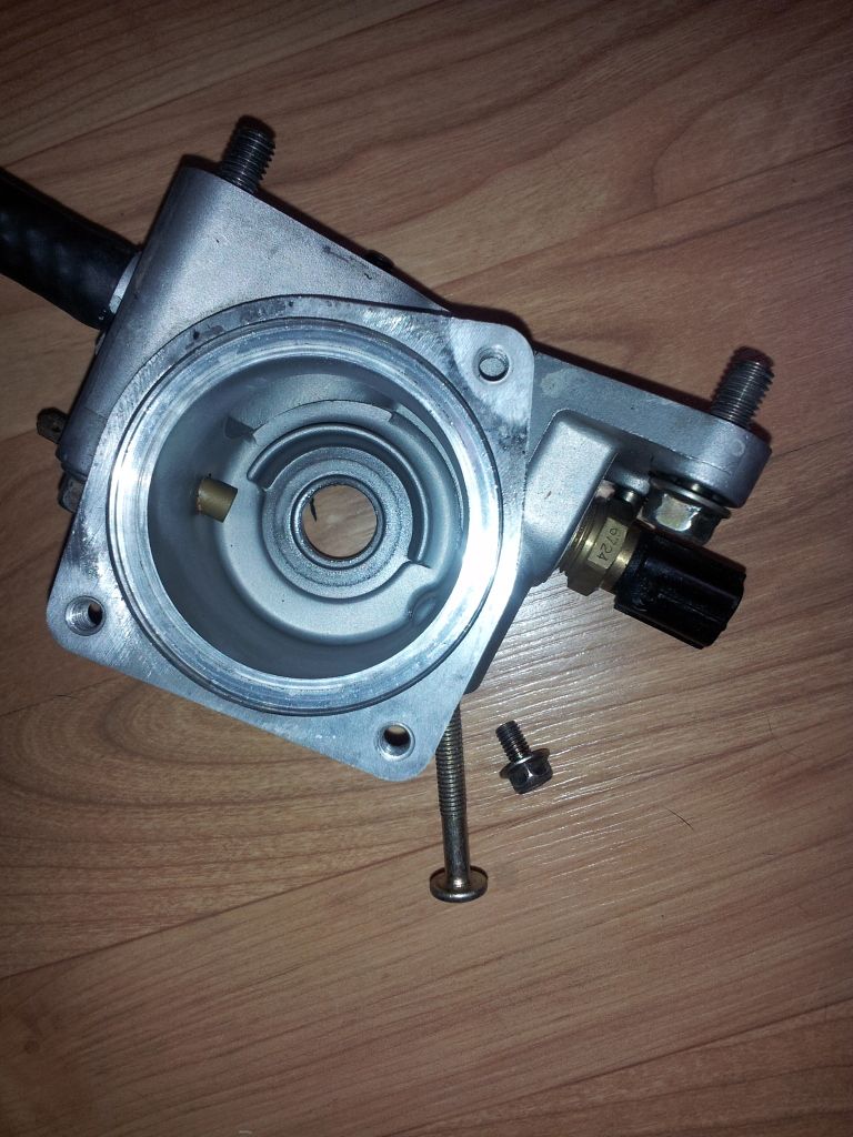
Here I've removed the short grounding bolt and replaced it with a very long M6 bolt, so it's easier to see the angle that the hole is at:
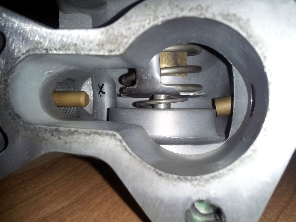
Based on visual estimation, I marked where the tip of the sender would come through into the inside of the housing with an X:
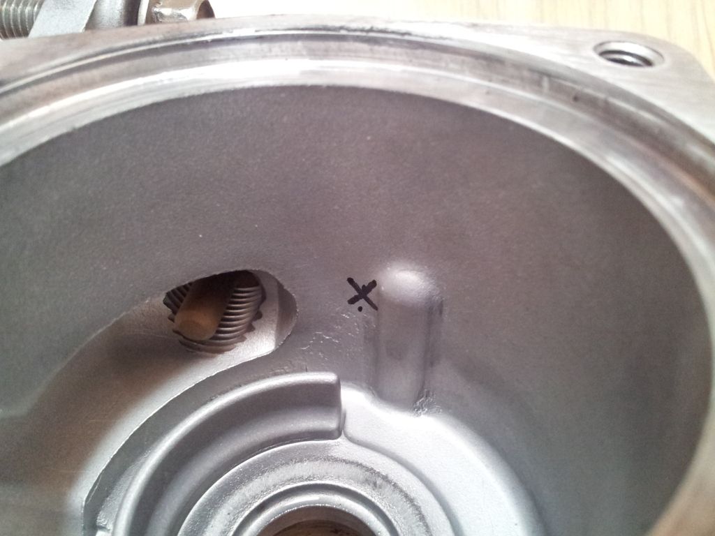
And while I don't know for sure until I have the actual 1/8" NPT sender for my gauge, it looks like there'll be enough room for it, and not run into the thermostat:
The blind hole for that M6 grounding bolt is 15.5mm deep, so that should be plenty of thread depth to seal the 1/8 NPT.
Looks like the drill bit I'll need to use before running the 1/8" NPT tap is a 11/32" or "R" (.339"): http://weldingweb.com/showthread.php?t=27450
And there's enough surface area for the shoulder of the sensor to rest against (that flat area is a little bigger than 13mm (.51") in diameter, since that's the diameter of the flanged M6 bolt head. And there is plenty of room around that area of the thermostat housing, in general, for the much larger overall size of the new temperature sensor.
For the wire that used to be grounded there, I figure I can just change extend the wire slightly, put a bigger ring terminal on it, and ground it to one of the four bolts that attach the thermostat housing to the end of the head.
What am I missing here? Seems like this should work great. But I've been wrong before, so please let me know if you see a big flaw or problem in my gameplan.
Thanks!
I use my Evo on the track, and a recent overheating issue has convinced me I should have a coolant temperature gauge with a programmable warning light (easy to miss the fact that your OEM temp gauge is pegged when you're hot lapping and/or in traffic on track).
I know it's possible to install a coolant temp sender in the radiator hose with an adapter available from Prosport or Greddy, but I'm not a fan of method for two reasons:
- In the case that the thermostat sticks shut (or partially closed), I won't know I have a problem
- Cutting into the radiator hose to install the adapter adds two full hose-circumference areas of potential leaks
I've also seen this thread on NorCalEvo about making an adapter for a coolant sensor off the little hose between the thermostat housing and the turbo:
http://www.norcalevo.net/threads/555...ensor-adapter?
- but this method involves using a lot of hardware store parts for no good reason, and again more potential for coolant leaks by cutting into that hose.
SO, with all that out of the way, I'm convinced the best way to add an additional coolant temp sensor is to tap the thermostat housing itself.
I realize I could just unscrew the OEM 1/8 NPT sender, which I'm assuming is for the factory temp gauge, and then screw in the 1/8 NPT sender for my aftermarket coolant temp gauge, but I like the idea of having the OEM gauge working as well, just in case the aftermarket gauge loses power, or the aftermarket gauge sender dies while I'm on track.
Okay, on to the pictures/plan.
Here's the Evo9 thermostat housing from the top:
And in this picture, you can see the 10mm-head grounding point bolt that I'm planning on using for the location to tap to 1/8" NPT for the new temperature sender:
Here I've removed the short grounding bolt and replaced it with a very long M6 bolt, so it's easier to see the angle that the hole is at:
Based on visual estimation, I marked where the tip of the sender would come through into the inside of the housing with an X:
And while I don't know for sure until I have the actual 1/8" NPT sender for my gauge, it looks like there'll be enough room for it, and not run into the thermostat:
The blind hole for that M6 grounding bolt is 15.5mm deep, so that should be plenty of thread depth to seal the 1/8 NPT.
Looks like the drill bit I'll need to use before running the 1/8" NPT tap is a 11/32" or "R" (.339"): http://weldingweb.com/showthread.php?t=27450
And there's enough surface area for the shoulder of the sensor to rest against (that flat area is a little bigger than 13mm (.51") in diameter, since that's the diameter of the flanged M6 bolt head. And there is plenty of room around that area of the thermostat housing, in general, for the much larger overall size of the new temperature sensor.
For the wire that used to be grounded there, I figure I can just change extend the wire slightly, put a bigger ring terminal on it, and ground it to one of the four bolts that attach the thermostat housing to the end of the head.
What am I missing here? Seems like this should work great. But I've been wrong before, so please let me know if you see a big flaw or problem in my gameplan.
Thanks!
1/8th npt is a tapered thread so the sensor doesnt need to go in as far as its shoulder , as its screwed in the taper on both hole and sensor seal one another . get a piece of similar alloy and practice on it .
I've tapped cast aluminum engine parts before for NPT threads before, and this should be pretty straightforward especially since most of the hole's depth has already been machined from the factory. All I have to do is drill through to the inside of the housing with a 3/16" bit, enlarge the bore carefully to 11/32", and then tap it with a sharp, greased 1/8" NPT tap.
Just wanted to make sure I'm not overlooking an obvious reason why this wouldn't work before I started the project.

You're right, looking at the OEM 1/8" NPT temp sensor, the way it's threaded in, it stops about 4mm before the shoulder reaches the Tstat housing.
I've tapped cast aluminum engine parts before for NPT threads before, and this should be pretty straightforward especially since most of the hole's depth has already been machined from the factory. All I have to do is drill through to the inside of the housing with a 3/16" bit, enlarge the bore carefully to 11/32", and then tap it with a sharp, greased 1/8" NPT tap.
Just wanted to make sure I'm not overlooking an obvious reason why this wouldn't work before I started the project.
I've drilled, tapped, and installed the temp sender for my aftermarket water temp gauge (Speedhut GL-WTR-01), but I haven't actually reinstalled the thermostat housing on the car and tested it for leaks yet, as the rest of the motor isn't back together yet.
But, overall the job went well, and I think with the use of Permatex high temperature sealant on the threads, it shouldn't have any leaking issues.
Tapping the Tstat housing was considerably more difficult than I anticipated, due to the small size of the thermostat, and difficulty in generating the necessary torque on the tap handle to tap the aluminum.
I was concerned about possibly cracking the housing by threading it too far or too quickly, so it a took a long time to finish the job�lots of removing the tap, cleaning out the fresh shavings, cleaning the tap, applying fresh WD-40, cranking the tap in another 180 degrees, repeated about 15 times.
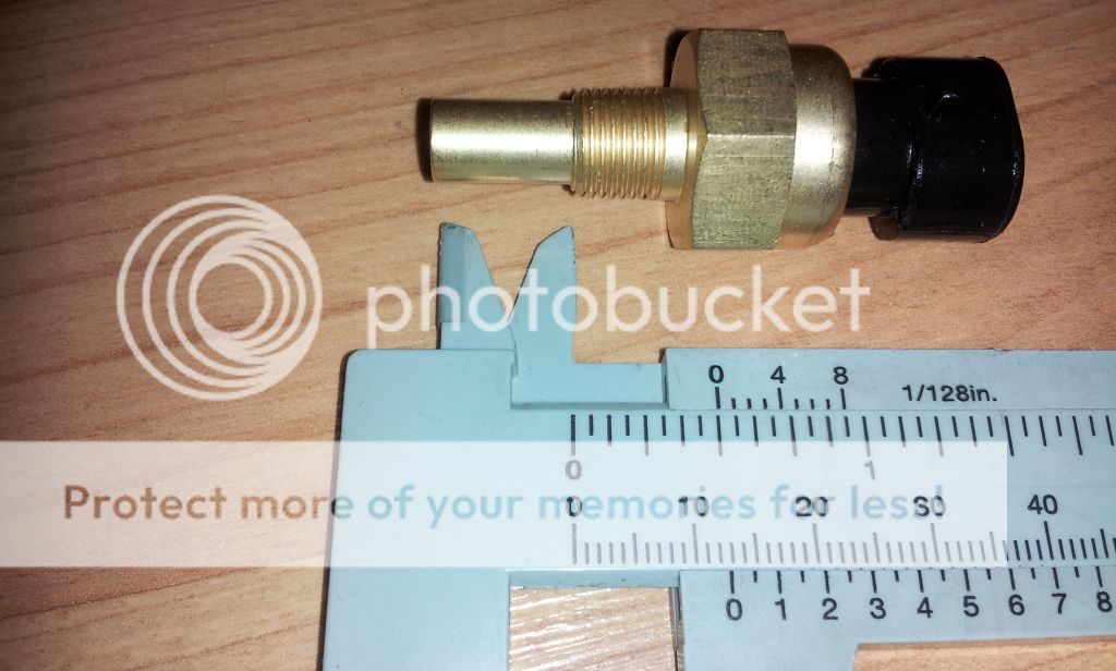
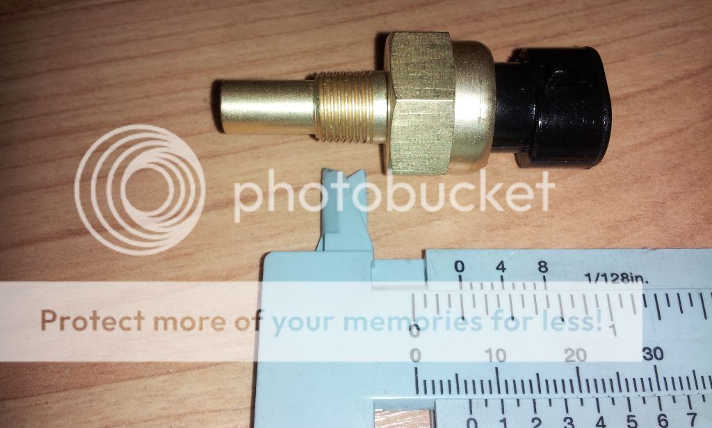
Measuring the sender... you can see the length of the sensing tip is about 1/2", and the actual threaded area only 1/4":
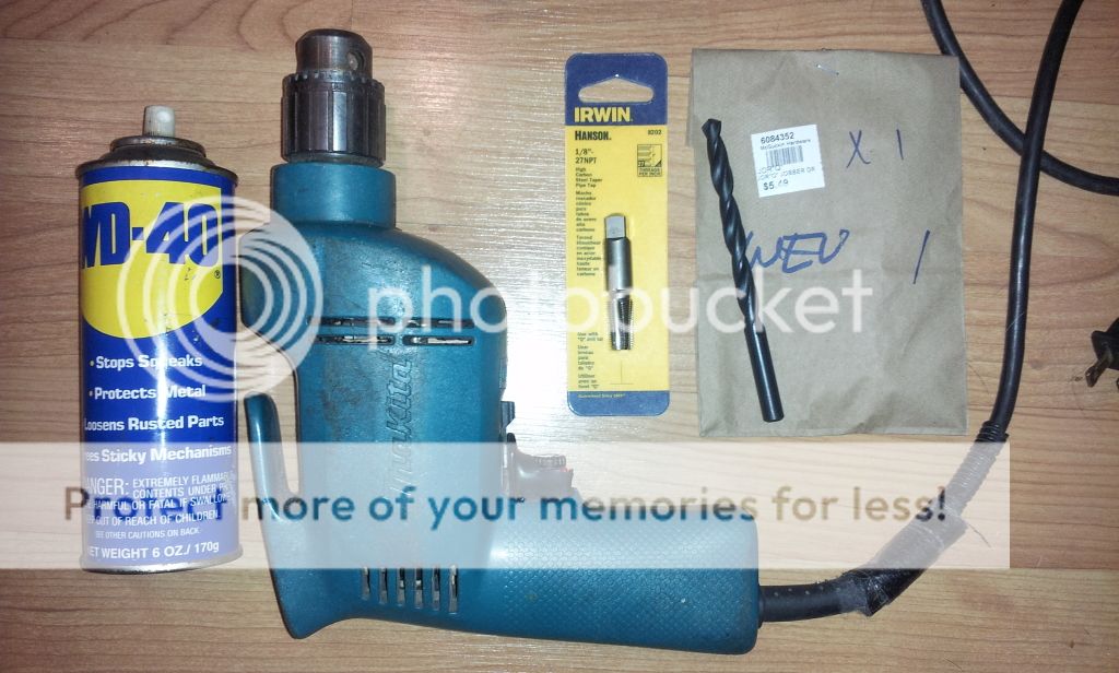
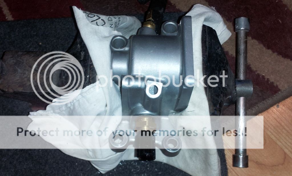
Tools/materials required... actually, I used a LOT more stuff than this, including two different Unibits, a tapered reamer, a variety of drill bits, and even a carbide bit for shaping the edge of the hole on the inside of the housing:
I did my initial drilling through with a 3/16" diameter bit (what fit nicely within the M6 threads of the existing hole)... wasn't too far off on my estimate of where it would come through:
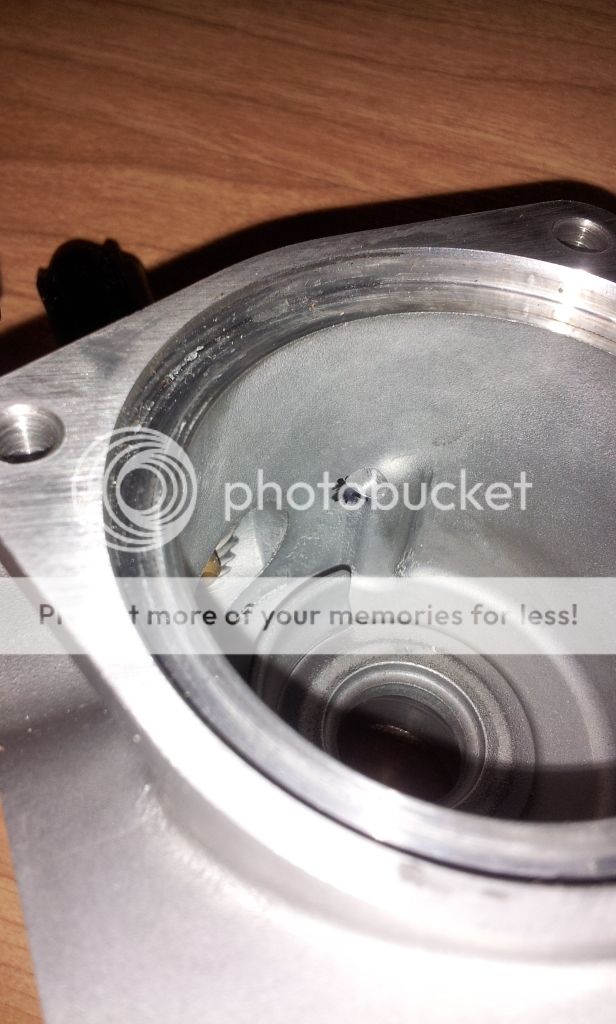
I held the Tstat housing in a small vise, with multi-layered T-shirt rag to protect it from damage, especially on the crucial machined gasket surface to the cylinder head:
After drilling with incrementally bigger drill bigs, up to the proper "Q" sized bit that is the correct size for the 1/8" NPT tap:

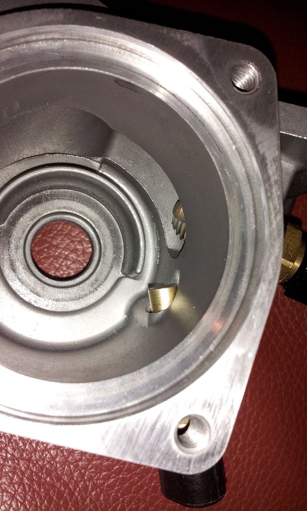
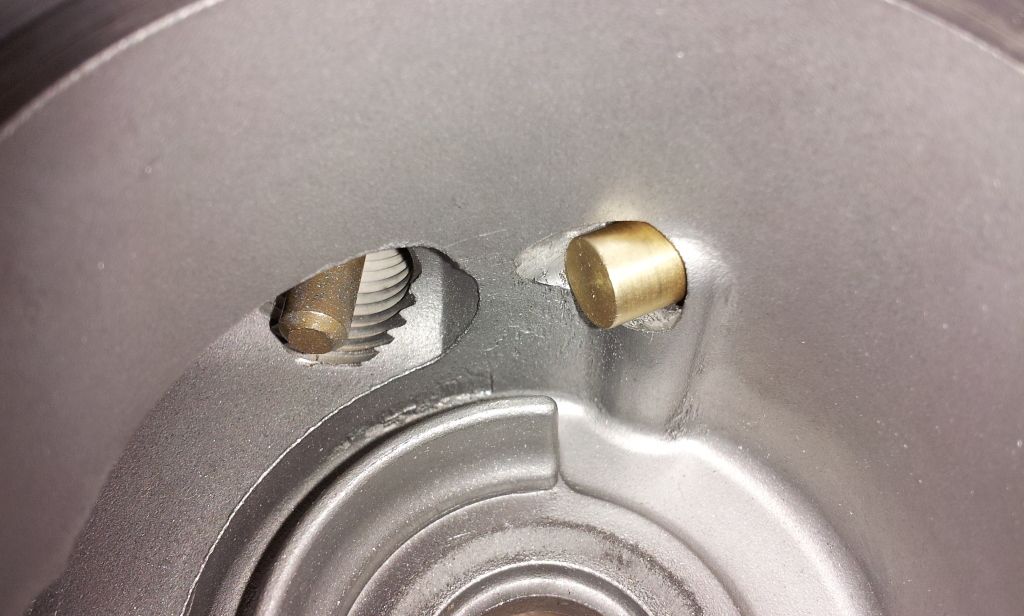
You'll notice in the pic above I didn't actually bore all the way through with the Q bit. I thought I was being clever by doing this, by keeping the hole around the tip of the sender as small as possible, but I wasn't. This was quite stupid, actually. Why? Because I was unable to get the tap to go in at EXACTLY the same angle as the hole I drilled, which meant that the sender tip got hung up on the wall of the Tstat housing before it made it out of the hole.
I didn't realize this until AFTER I'd tapped the hole, so I couldn't go back in with a larger drill bit to open up the hole on the inside of the housing... I had to do it with a drill bit and carbide bit from the other way, which was very difficult. Also, you WANT to have a little space all the way around the tip of the temp sensor, so the coolant can better surround it.
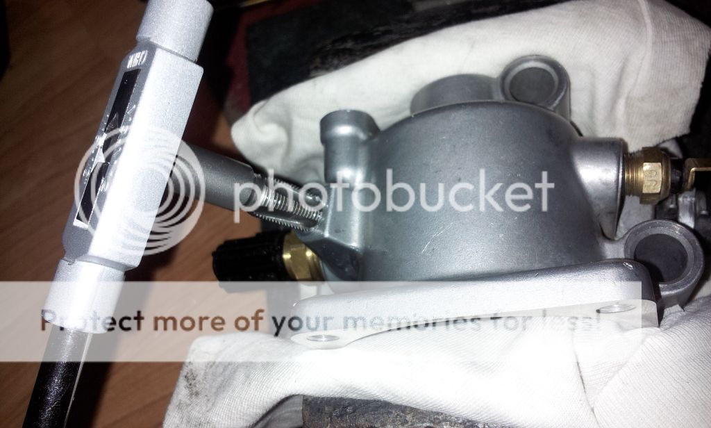
Getting the tap started is the scariest part because if the get the angle wrong in the first couple threads, the entire tapping is going to be crooked/F'ed up. I couldn't get the tap started with any confidence that I was close to right on my angle, so I used a tapered reamer to allow the tap to sit at least a millimeter or so inside the hole before it started to cut. This made a big difference:

Way past the point of no return here... you'll notice I'm using a Harbor Freight tap handle. Really glad I had that in my tool collection, because it would have SUCKED to try to do this with a crescent wrench on the end of the tap:
Done:

But, overall the job went well, and I think with the use of Permatex high temperature sealant on the threads, it shouldn't have any leaking issues.
Tapping the Tstat housing was considerably more difficult than I anticipated, due to the small size of the thermostat, and difficulty in generating the necessary torque on the tap handle to tap the aluminum.
I was concerned about possibly cracking the housing by threading it too far or too quickly, so it a took a long time to finish the job�lots of removing the tap, cleaning out the fresh shavings, cleaning the tap, applying fresh WD-40, cranking the tap in another 180 degrees, repeated about 15 times.
Measuring the sender... you can see the length of the sensing tip is about 1/2", and the actual threaded area only 1/4":
Tools/materials required... actually, I used a LOT more stuff than this, including two different Unibits, a tapered reamer, a variety of drill bits, and even a carbide bit for shaping the edge of the hole on the inside of the housing:
I did my initial drilling through with a 3/16" diameter bit (what fit nicely within the M6 threads of the existing hole)... wasn't too far off on my estimate of where it would come through:
I held the Tstat housing in a small vise, with multi-layered T-shirt rag to protect it from damage, especially on the crucial machined gasket surface to the cylinder head:
After drilling with incrementally bigger drill bigs, up to the proper "Q" sized bit that is the correct size for the 1/8" NPT tap:
You'll notice in the pic above I didn't actually bore all the way through with the Q bit. I thought I was being clever by doing this, by keeping the hole around the tip of the sender as small as possible, but I wasn't. This was quite stupid, actually. Why? Because I was unable to get the tap to go in at EXACTLY the same angle as the hole I drilled, which meant that the sender tip got hung up on the wall of the Tstat housing before it made it out of the hole.
I didn't realize this until AFTER I'd tapped the hole, so I couldn't go back in with a larger drill bit to open up the hole on the inside of the housing... I had to do it with a drill bit and carbide bit from the other way, which was very difficult. Also, you WANT to have a little space all the way around the tip of the temp sensor, so the coolant can better surround it.
Getting the tap started is the scariest part because if the get the angle wrong in the first couple threads, the entire tapping is going to be crooked/F'ed up. I couldn't get the tap started with any confidence that I was close to right on my angle, so I used a tapered reamer to allow the tap to sit at least a millimeter or so inside the hole before it started to cut. This made a big difference:
Way past the point of no return here... you'll notice I'm using a Harbor Freight tap handle. Really glad I had that in my tool collection, because it would have SUCKED to try to do this with a crescent wrench on the end of the tap:
Done:
Trending Topics

The waterneck is AFTER the thermostat... as I stated in my first post, in the case that the thermostat sticks shut (or partially closed), I won't know I have a problem if I put the sensor after the thermostat. This is why Mitsubishi didn't locate its OEM coolant sensors in the waterneck either.


You might want to use proper tapping oil or thread wax ...they do a better job than WD40. The thread wax retains the shavings/chips on the tap itself
T handle will work much better than the crescent wrench.
That sensor in the pic is not sticking into the housing far enough, IMHO. I may go a bit further in on the threading and install.
Good job anyway...i have a mechanical temp gauge and inline hose adapter, but have not installed it as I too don't want leaks and prefer to get a better reading off the housing. Looks a lot easier than i thought.
Thanks for your post and pics
I used a tapping T-handle; I only mentioned the crescent wrench as a "that would have been really difficult/impossible" option.
Thanks for your feedback! I'm sure someone else could certainly do a better job than I did; I just wanted to document how it turned out for me, since when I was researching this idea, I couldn't find evidence of anyone who'd actually done it.
