
Wideband in clock position

Wideband in clock position
I believe there are some people out there that have done this. I have seen ebc's and tt but rarely widebands. I am planning to buy a zeitronix wideband:
http://www.zeitronix.com/Products/O2Meter/O2Meter.htm
and put it where the clock goes. I am trying to find out if this wideband will fit in this area and what issues I might run into. Any input would help before i make the purchase and let the trimming begin.
http://www.zeitronix.com/Products/O2Meter/O2Meter.htm
and put it where the clock goes. I am trying to find out if this wideband will fit in this area and what issues I might run into. Any input would help before i make the purchase and let the trimming begin.
that's a good idea, but im kind of confused. isnt that just a narrow band readout? are you planning to wire it to stock ecu like in those diagrams? if your planning on tuning or want more accurate readings then i wouldnt purchase that, unless theres a way to wire that to a wide band sensor. i do like the idea of having it in the clock spot though. looks small enough to take apart and stick it back there. if im wrong let me know, im still a newb to all this.


Ya, that is just for narrowband sensors, unless you can to a v to afr linear calculation in your head...or set your output from your wideband controller to something easy.
As for bung clocking, the best bet is between 9 ->3, directly avoiding 12ish. This is for 2 reasons:
1. Lower than the 9 - 3 can expose your sensor (really the ceramic inside the cover) to condensation/moisture that can collect before/during starting conditions. This can crack the ceramic leaving your sensor as an expensive bung plug
2. Avoid 12 o�clock (straight up) as exhaust/environment heat along with sensor heat will travel straight up the body of the sensor, shortening it's life.
Quick Tip - remember to a) use anti-seize on any metal-to-metal threads and b) replace the crush seal on the sensor and often times they leak.
Quick tip 2 - if you use anti-seize, it will burn any extra off. So when you first start it up after installation, you'll see a little smoke during its first heat cycle.
Quick tip 3- https://www.evolutionm.net/forums/search.php
Hope this helps
-Westy
Quick Tip - read and understand whats being asked before you post.
Yeah I actually already welded on an o2 bung when I put my exhaust on a while ago. I actually don't think I am going to go with that narrowband. I have a friend that actually defaced the clock and defaced a wideband and wired them together so it was the stock clock but actually read afr instead of the time. That what I am planning on doing. Thank you for the pictures! If Defi made a wideband, they would be making good money!
Trending Topics
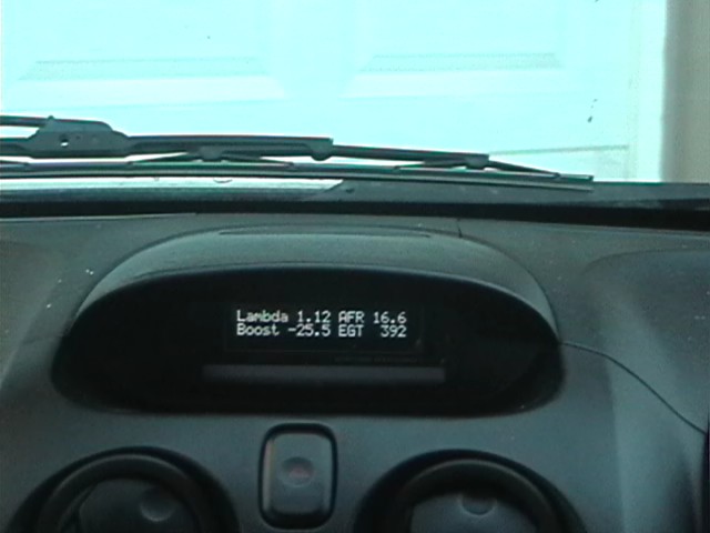
Just to make up for my fail of a response, I took the plunge and did it myself. It turned out great, but if you can get your buddy to somehow do it through the clock that would be ideal.
There is a lot of room there for something, as long as you clear the top trim clip and dept isn’t really an issue
I used a MOTEC PLM (lambda meter), which is rectangular, not round like an AEM/Defi. The meter/sensor itself is top of the line...
However some bad points...
1. I had to take the board out of the case, exposing the LCD and board, however it's built for racing, so it should be ok. I used some random clear plastic to cover the lcd once mounted protect the face.
2. I had to remove the two center vent open/close rollers to make room.
Driving around, its looks great once I determined what backlight intensity setting I wanted.
Hope this helped
-Westy
Love the idea. I am also looking for a nice place to out my Innovative LM1 "Brick" wide band display.
Have you seen this?
https://www.evolutionm.net/forums/ev...ul-gauges.html
Unfortunately I don't think that small gauge will work. It is for stock narrowband. You'd likely need to modify this one (http://www.zeitronix.com/Products/ZR-1/ZR-1.htm) to make it work. A small piece of acrylic from say a CD case and a little ingenuity would go a long way! I plan to buy the accessory gauge that Innovative offers and butcher the sucker to fit in the stock cluster.


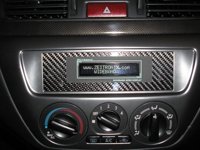
haha...I'm actually doing this right now! I'm using the Zeitronix wideband lcd display (http://www.zeitronix.com/Products/zt2/zt2.htm#LCD).
So far, I pulled the display apart and separated the main circuit for the lcd circuit board. Then I soldiered wires to the pins where the two boards connect so I can mount the main board remote from the lcd.
Next, I took apart the dash and removed the clock. The clock is held on by two tabs. These tabs are then cut off to make room for the lcd. Everything on the black plastic vent piece is removed (vents, the flaps, hazard button). You end up with the vent piece as a single piece of plastic. Then you have to do some slight trimming of the back of the vent piece to make room for the lcd.
This is the farthest i have gotten so far. By doing this, you will lose the ability to open and close you vents because there isn't enough room for the open/close mechanism and the lcd ( so it's always open now).
The lcd screen is too big to fit in the clock position but the part you actually read is a perfect fit in the hole.
I wish i had some pictures. This all probably sounds pretty confusing. I'll try to get some if there is enough interest ( i have to learn how to post pic again...lol)