
Boost Leak Testing - How and Why


Boost Leak Testing - How and Why
I have been asked to provide a writeup that explains the how and why of boost leak testing. It seems that many are unclear on all the details and rationale of this important test. I attempted to make a comprehensive writeup on the subject, which follows below:
PURPOSE
The quickest way to rob an otherwise healthy turbo engine of performance is to introduce a pressure leak within the intake system. The more complex and segmented the intake system, the greater the statistical possibilities for a leak to occur. One thing I�ve realized in dealing with EVOs is that at least 2/3 of them seem to be running the roads with boost leaks that need attention. Boost leaks tend to go unnoticed until or unless one conducts a boost leak test, which should be done sooner than later. Until the leaks are remedied, there will be some degree of reduced compressor efficiency and power, higher intake air temps, slower spool characteristics, and tuning irregularities. If you�ve invested your hard-earned money into upgrading your EVO, you don�t want any of this.
Every turbo car owner should test for leaks periodically, and especially after any time a piece of the pressurized area is removed for service, etc. Checking for boost leaks involves a simple pressure test of the intake system. So long as one has access to compressed air source, only a few simple tools are required.
MATERIALS
Compressed air source
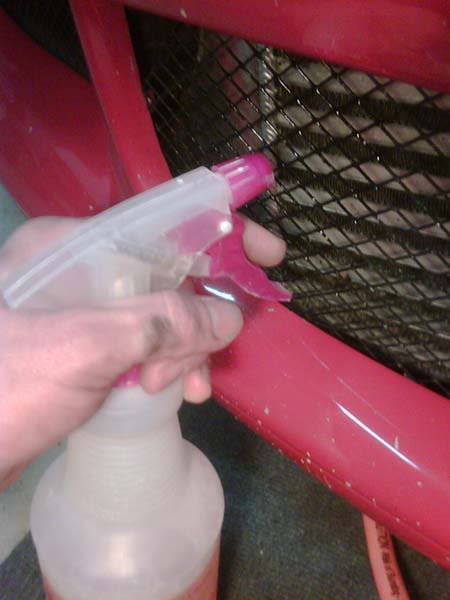
Spray bottle with soapy water
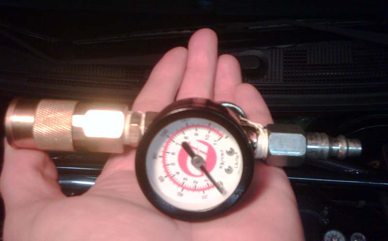
Pressure regulator with male and female quick connect fittings
Turbo compressor pressure cap
Means of sealing open lines and fittings (rubber caps, plugs, etc.)
Hairspray (pump bottle)
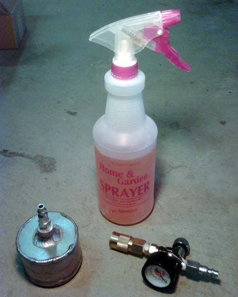
Inexpensive pressure regulator with quick connect fittings - try better auto parts stores
PROCEDURE
Step 1
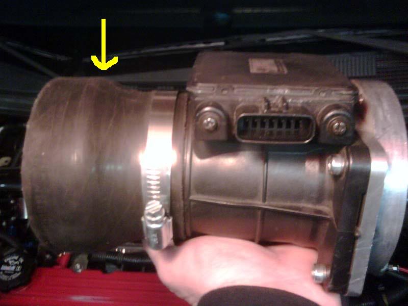
The entry point of the turbo must be made accessible and pressure tight. This is done by disconnecting part of the intake system from the entrance to the turbo and fitting a short section of silicone adapter tubing to connect the pressure cap to the turbo compressor. Many aftermarket intake systems use a silicone 4�-3� reducer to connect the intake tubing to the MAF. If you don�t already have something like this, get one appropriately sized to fit your turbo.
Silicone reducer (4"-3")
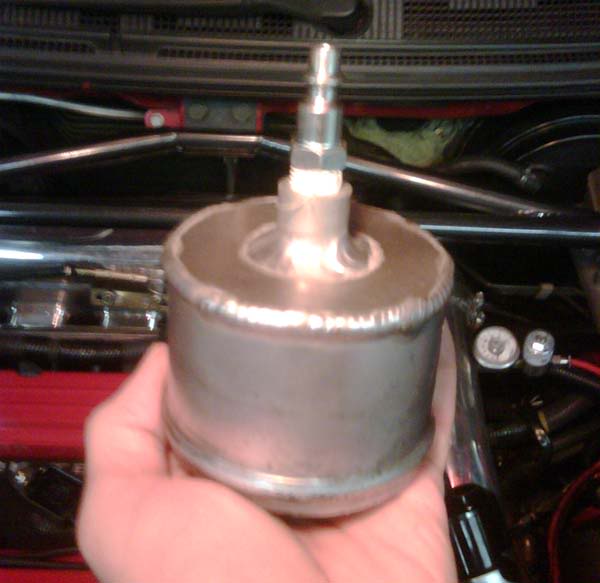
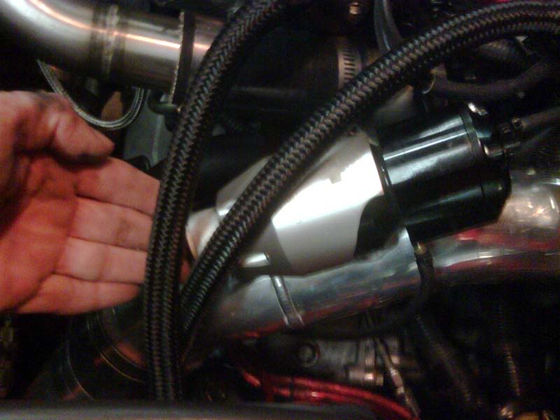
The turbo pressure cap consists of a piece of aluminum tubing with one sealed end. The one I�m using is a 3� diameter piece that fits snugly into the silicone adapter. There is a quick connect fitting on the sealed end and a rolled lip on the open end. A good fabricator can put one of these together. The one I am holding in the photo comes from MP Fab.
3" turbo pressure cap
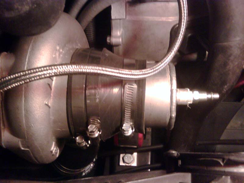
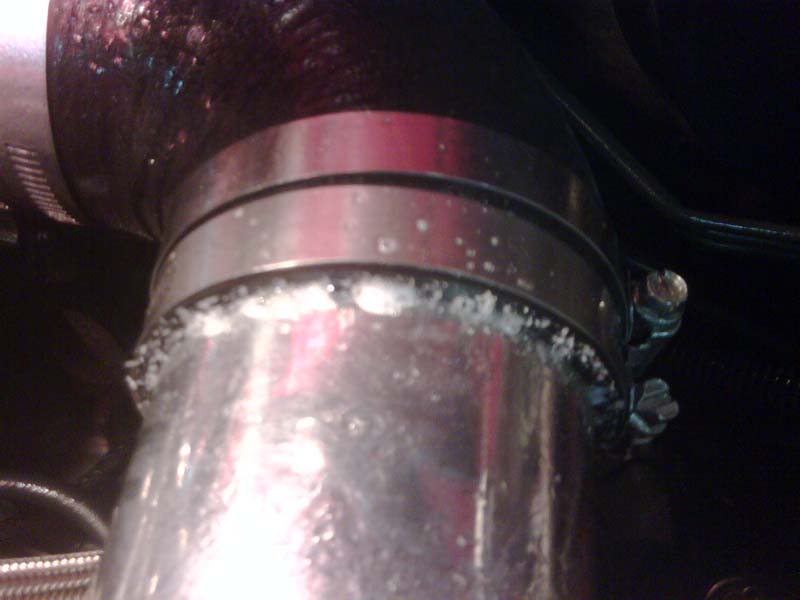
Some turbos do not have a rolled lip at the compressor flange. This usually creates a slippage problem when conducting a boost leak test that results in a loud, startling pop. This can be almost entirely eliminated by applying hairspray around the flange with your finger, and using 2 hose clamps to secure the silicone adapter to the compressor flange. We want to be able to conduct the test with at least the same boost pressure that we expect to use in the real world, and that requires very secure connections.
Turbo connections must be pressure tight. It's not as easy as it seems.
Step 2
You need to trace the intake system from the compressor outlet to the intake manifold, being mindful of any pressure signal taps that lead to something that would bleed air. Be sure you can identify each and every tap into the intake system. If any of these are open-ended, they should be sealed for the test. For example:
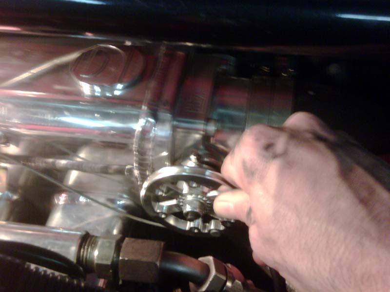
- A manual boost controller is effectively a controlled pressure leak. The boost signal line should be disconnected from the manual boost controller and plugged.
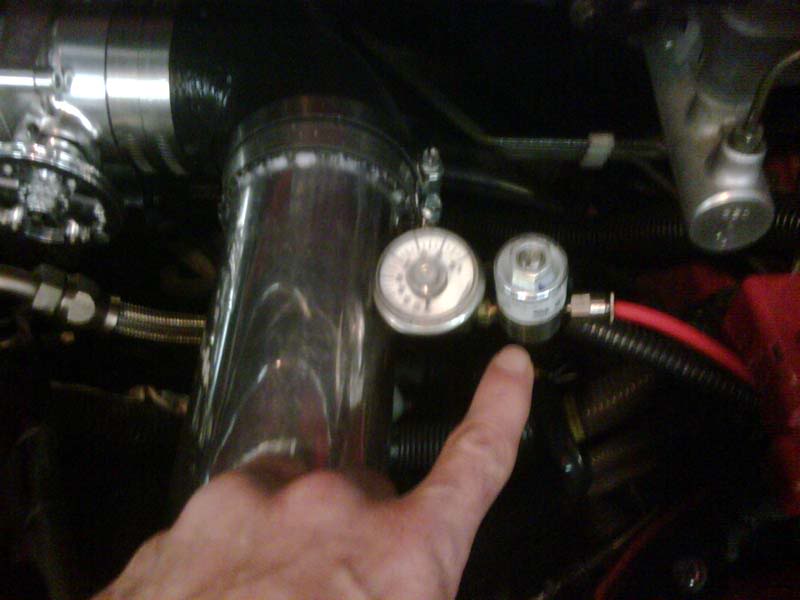
- A water or methanol injection system should be fitted with a normally closed solenoid valve in the injection line. If not, there will be an uncontrolled pressure leak that aside from being a source of leakage for the test, can create pump priming issues when the engine is in operation. Be advised.
Solenoid valve - a good idea
- If there is a recirculating blowoff valve, disconnect the recirculated air line from the valve.
- The PCV valve can be checked by disconnecting the PCV valve from the cam cover itself, leaving the other end connected to the intake manifold.
Anything that bleeds air during a boost leak test also bleeds it under real world conditions, so keep that in mind.
Step 3
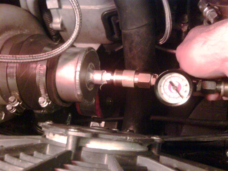
With the aforementioned lines sealed and the pressure source connected, we are ready to slowly introduce pressure into the system. Gradually increase the pressure to 20 psi, constantly watching that the silicone adapter is not slipping. If it begins to slip, prepare yourself for a loud, annoying POP!
Be slow with the regulator valve. It takes several seconds to pressurize the system.
With 20 psi in the system, make the following checks:
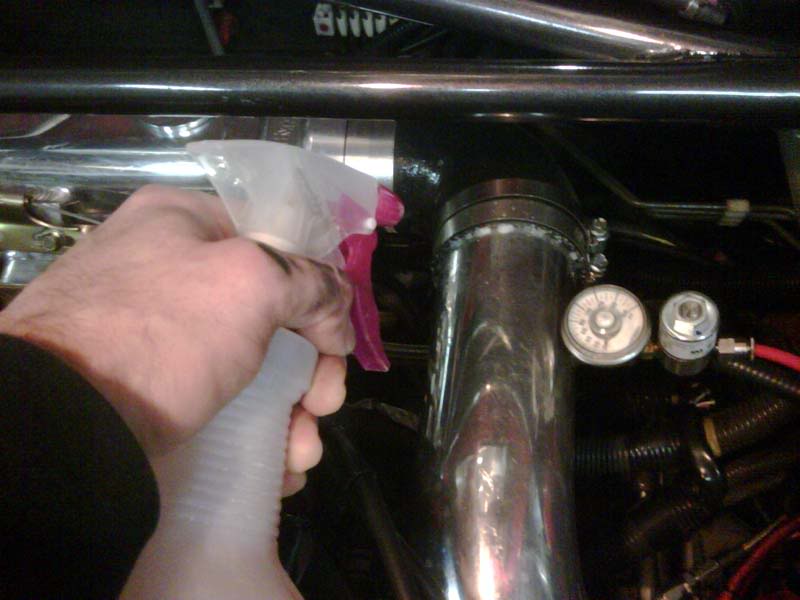
- Spray ALL tubing connections while watching for bubbles and listening for hissing. A few tiny, foamy bubbles that slowly seep from joint are acceptable. Larger bubbles that rapidly form and pop are indicative of a leaky joint. Where a leaky joint is discovered, disconnect and carefully reconnect the joint. Doubling the hose clamps is an inexpensive way to make more secure connections at potentially leaky joints. If this is the first time the system is pressure tested, it is wise to get under the car and check the LICP connections. The best way to do this is to conduct the test with the car on a rack with the undertray removed.
Spray all coupler seams.
Tiny, slowly oozing bubbles are ok.
- Spray the IC where the core meets the end tanks. Look for bubbles and listen for hissing. Some IC cores can be leaky, and that is a problem that involves removing the IC and possibly the end tanks to bolster the core end seams with epoxy.
This is easier to do with the front bumper cover off.
- Run your finger along the backside of the turbo compressor cover. If you feel a jet of air, from either the cover seam or at the head of a cover bolt, be prepared to remove the compressor cover and reaffix with a bead of gasket sealer (e.g. Permatex gray). This is a common problem with newer Garrett turbo covers.
- Check that no air is being vented from the blowoff valve recirculated air line. If there is a leak, the valve needs either adjustment or replacement. If there is a VTA valve, check for a leak at the dump.
No air leak here!
- Check the open cam cover end of the PCV valve and verify that no air is being vented. If there is a leak, replace the PCV valve without delay.
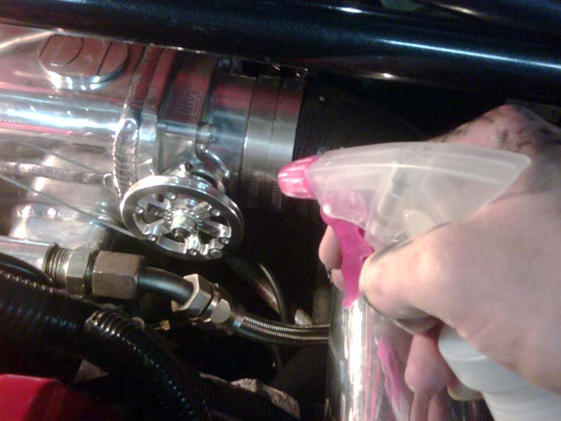
- There may be audible hissing at the throttle body. One cause is air passing through the idle air control valve. That hiss should change in tone or almost disappear if the throttle plate is opened manually.
Hiss is silenced with TB movement
- Check the throttle body shaft ends for air leaks. It�s not easy to get a perfect seal here, but whistling jets of air that blow large bubbles are unacceptable. If it is a well-used factory throttle body, consider replacing the shaft seals.
Check for leaks here.
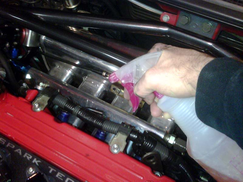
- Check the injector seals for leaks where the injectors mate to the intake manifold runners. A leak at an injector means the o-ring should either be checked and re-seated, or replaced.
Look and listen carefully for leaks here.
CONCLUSION
When you are satisfied that all is well and any leaks have been fixed, very slowly turn the pressure up to at least the anticipated real world boost pressure level, and listen to all parts of the system carefully for any new sounds or leaks as the pressure rises. Most leaks (especially large ones) are exposed at low pressures, but some don�t show up unless there is considerable pressure in the system, which is the worst possible time to have a leak. Make absolutely sure the blowoff valve is air tight at the maximum pressure.
If you�ve discovered a large leak or several small leaks, be advised that once they are fixed, you may find that some tuning adjustments may need to be made, especially with mass air systems. This is why it is always best to pressure test your system before the tuning session � unless you don�t mind taking a chance on having to tune it twice.
Ted B.
PURPOSE
The quickest way to rob an otherwise healthy turbo engine of performance is to introduce a pressure leak within the intake system. The more complex and segmented the intake system, the greater the statistical possibilities for a leak to occur. One thing I�ve realized in dealing with EVOs is that at least 2/3 of them seem to be running the roads with boost leaks that need attention. Boost leaks tend to go unnoticed until or unless one conducts a boost leak test, which should be done sooner than later. Until the leaks are remedied, there will be some degree of reduced compressor efficiency and power, higher intake air temps, slower spool characteristics, and tuning irregularities. If you�ve invested your hard-earned money into upgrading your EVO, you don�t want any of this.
Every turbo car owner should test for leaks periodically, and especially after any time a piece of the pressurized area is removed for service, etc. Checking for boost leaks involves a simple pressure test of the intake system. So long as one has access to compressed air source, only a few simple tools are required.
MATERIALS
Compressed air source
Spray bottle with soapy water
Pressure regulator with male and female quick connect fittings
Turbo compressor pressure cap
Means of sealing open lines and fittings (rubber caps, plugs, etc.)
Hairspray (pump bottle)
Inexpensive pressure regulator with quick connect fittings - try better auto parts stores
PROCEDURE
Step 1
The entry point of the turbo must be made accessible and pressure tight. This is done by disconnecting part of the intake system from the entrance to the turbo and fitting a short section of silicone adapter tubing to connect the pressure cap to the turbo compressor. Many aftermarket intake systems use a silicone 4�-3� reducer to connect the intake tubing to the MAF. If you don�t already have something like this, get one appropriately sized to fit your turbo.
Silicone reducer (4"-3")
The turbo pressure cap consists of a piece of aluminum tubing with one sealed end. The one I�m using is a 3� diameter piece that fits snugly into the silicone adapter. There is a quick connect fitting on the sealed end and a rolled lip on the open end. A good fabricator can put one of these together. The one I am holding in the photo comes from MP Fab.
3" turbo pressure cap
Some turbos do not have a rolled lip at the compressor flange. This usually creates a slippage problem when conducting a boost leak test that results in a loud, startling pop. This can be almost entirely eliminated by applying hairspray around the flange with your finger, and using 2 hose clamps to secure the silicone adapter to the compressor flange. We want to be able to conduct the test with at least the same boost pressure that we expect to use in the real world, and that requires very secure connections.
Turbo connections must be pressure tight. It's not as easy as it seems.
Step 2
You need to trace the intake system from the compressor outlet to the intake manifold, being mindful of any pressure signal taps that lead to something that would bleed air. Be sure you can identify each and every tap into the intake system. If any of these are open-ended, they should be sealed for the test. For example:
- A manual boost controller is effectively a controlled pressure leak. The boost signal line should be disconnected from the manual boost controller and plugged.
- A water or methanol injection system should be fitted with a normally closed solenoid valve in the injection line. If not, there will be an uncontrolled pressure leak that aside from being a source of leakage for the test, can create pump priming issues when the engine is in operation. Be advised.
Solenoid valve - a good idea
- If there is a recirculating blowoff valve, disconnect the recirculated air line from the valve.
- The PCV valve can be checked by disconnecting the PCV valve from the cam cover itself, leaving the other end connected to the intake manifold.
Anything that bleeds air during a boost leak test also bleeds it under real world conditions, so keep that in mind.
Step 3
With the aforementioned lines sealed and the pressure source connected, we are ready to slowly introduce pressure into the system. Gradually increase the pressure to 20 psi, constantly watching that the silicone adapter is not slipping. If it begins to slip, prepare yourself for a loud, annoying POP!
Be slow with the regulator valve. It takes several seconds to pressurize the system.
With 20 psi in the system, make the following checks:
- Spray ALL tubing connections while watching for bubbles and listening for hissing. A few tiny, foamy bubbles that slowly seep from joint are acceptable. Larger bubbles that rapidly form and pop are indicative of a leaky joint. Where a leaky joint is discovered, disconnect and carefully reconnect the joint. Doubling the hose clamps is an inexpensive way to make more secure connections at potentially leaky joints. If this is the first time the system is pressure tested, it is wise to get under the car and check the LICP connections. The best way to do this is to conduct the test with the car on a rack with the undertray removed.
Spray all coupler seams.
Tiny, slowly oozing bubbles are ok.
- Spray the IC where the core meets the end tanks. Look for bubbles and listen for hissing. Some IC cores can be leaky, and that is a problem that involves removing the IC and possibly the end tanks to bolster the core end seams with epoxy.
This is easier to do with the front bumper cover off.
- Run your finger along the backside of the turbo compressor cover. If you feel a jet of air, from either the cover seam or at the head of a cover bolt, be prepared to remove the compressor cover and reaffix with a bead of gasket sealer (e.g. Permatex gray). This is a common problem with newer Garrett turbo covers.
- Check that no air is being vented from the blowoff valve recirculated air line. If there is a leak, the valve needs either adjustment or replacement. If there is a VTA valve, check for a leak at the dump.
No air leak here!
- Check the open cam cover end of the PCV valve and verify that no air is being vented. If there is a leak, replace the PCV valve without delay.
- There may be audible hissing at the throttle body. One cause is air passing through the idle air control valve. That hiss should change in tone or almost disappear if the throttle plate is opened manually.
Hiss is silenced with TB movement
- Check the throttle body shaft ends for air leaks. It�s not easy to get a perfect seal here, but whistling jets of air that blow large bubbles are unacceptable. If it is a well-used factory throttle body, consider replacing the shaft seals.
Check for leaks here.
- Check the injector seals for leaks where the injectors mate to the intake manifold runners. A leak at an injector means the o-ring should either be checked and re-seated, or replaced.
Look and listen carefully for leaks here.
CONCLUSION
When you are satisfied that all is well and any leaks have been fixed, very slowly turn the pressure up to at least the anticipated real world boost pressure level, and listen to all parts of the system carefully for any new sounds or leaks as the pressure rises. Most leaks (especially large ones) are exposed at low pressures, but some don�t show up unless there is considerable pressure in the system, which is the worst possible time to have a leak. Make absolutely sure the blowoff valve is air tight at the maximum pressure.
If you�ve discovered a large leak or several small leaks, be advised that once they are fixed, you may find that some tuning adjustments may need to be made, especially with mass air systems. This is why it is always best to pressure test your system before the tuning session � unless you don�t mind taking a chance on having to tune it twice.
Ted B.

Thread
Thread Starter
Forum
Replies
Last Post
Ted B
Evo General
315
Jul 10, 2025 03:45 PM
Ted B
Evo Engine / Turbo / Drivetrain
58
Jun 21, 2012 01:29 PM
Ted B
Evo How Tos / Installations
3
Jan 12, 2011 12:44 AM