
Vent Boost Gauge VBG1 ( Digital Led Bars & numerics )


Evolving Member
Joined: May 2011
Posts: 140
Likes: 0
From: Tampa

Ok good your afr is great. What wideband are you using? Look in manual there is a Section on aux input "section 9". It will tell you to scroll through to the wideband you are using.
Their website says it's compatible with LC-1 and AEM AFR analog output but I will definitely double check before purchasing.
Is it difficult to hook a wideband up to this unit? I have all the vac tubes and afr lines run to the dash already so is it pretty much just PnP?
Is it difficult to hook a wideband up to this unit? I have all the vac tubes and afr lines run to the dash already so is it pretty much just PnP?

Thread Starter
Newbie
Joined: Feb 2012
Posts: 14
Likes: 0
From: Arlington
Part Number 30-2310 and 30-5130
AEM UEGO CONTROLLER:
AFR = 2.375(V) + 7.3125
30-4100
Gauge-Type UEGO Controller: (note jumper config)
y = 2x + 10

Evolving Member
Joined: May 2011
Posts: 140
Likes: 0
From: Tampa
Their website says it's compatible with LC-1 and AEM AFR analog output but I will definitely double check before purchasing.
Is it difficult to hook a wideband up to this unit? I have all the vac tubes and afr lines run to the dash already so is it pretty much just PnP?
Is it difficult to hook a wideband up to this unit? I have all the vac tubes and afr lines run to the dash already so is it pretty much just PnP?
Thread Starter
Newbie
Joined: Feb 2012
Posts: 14
Likes: 0
From: Arlington
I'm using the LC1
Also try to test the analog output by forcing it to a known state. By putting 2.5 into both the Min voltage setpoint and the Max you can force the LC1 to fix a steady output voltage.
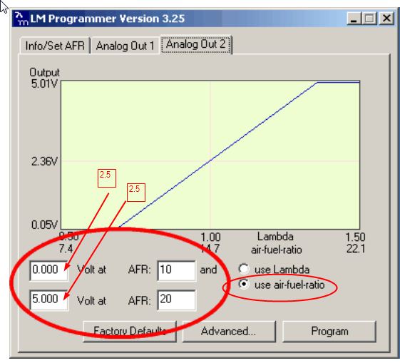
Do this and the VBG1 should read 15 AFR. at 2.5 volts. If you have a volt meter check this voltage at the VBG1 - LC1 analog connection point.
Evolving Member
Joined: May 2011
Posts: 140
Likes: 0
From: Tampa
Whoa sorry I did not catch that - There are tons of people running LC-1 into a VBG1. Be sure you are are setting the output for the correct analog channel. The manual http://www.gtboostgauge.com/VBG1%20-...or%20V1.06.pdf describes using analog output 2 - which is the BROWN wire.
Also try to test the analog output by forcing it to a known state. By putting 2.5 into both the Min voltage setpoint and the Max you can force the LC1 to fix a steady output voltage.
Attachment 189320
Do this and the VBG1 should read 15 AFR. at 2.5 volts. If you have a volt meter check this voltage at the VBG1 - LC1 analog connection point.
Yah I'm using the brown wire, I don't have a volt meter but I'll try the 2.5v thing in log works And see what happens.