Evo X Boost Gauge Install ,No splicing, No firewall drilling,Pics+Vid= Clean As Hell
 Dec 30, 2013, 07:04 PM
#241
Newbie
iTrader: (1)

Join Date: Jun 2011
Location: California
Posts: 18
Likes: 0
Received 0 Likes
on
0 Posts
Hi all!
I have a Blitz mirror drive gauge and followed the wiring instructions here, everything works except gauge won't completely turn off with car. Instead, it dims and buttons are still functional. Tried remove constant power, gauge turns on and off with car perfectly, but no memory function since no consistent power.
Please help! Thanks in advance!
 Jan 2, 2014, 03:11 PM
#242
Hi all!
I have a Blitz mirror drive gauge and followed the wiring instructions here, everything works except gauge won't completely turn off with car. Instead, it dims and buttons are still functional. Tried remove constant power, gauge turns on and off with car perfectly, but no memory function since no consistent power.
Please help! Thanks in advance!
I have a Blitz mirror drive gauge and followed the wiring instructions here, everything works except gauge won't completely turn off with car. Instead, it dims and buttons are still functional. Tried remove constant power, gauge turns on and off with car perfectly, but no memory function since no consistent power.
Please help! Thanks in advance!
Jan 3, 2014, 08:26 AM
#243
Newbie
iTrader: (1)
Join Date: Jun 2011
Location: California
Posts: 18
Likes: 0
Received 0 Likes
on
0 Posts
This is how I wire it,

When turn on,

When shut off,

Please help! Thanks!
 Mar 15, 2014, 04:54 PM
#245
Evolving Member
I've been trying to get my AEM installed but I'm worried that I have the right hose and also if I am looking in the right place I don't think the supplied T fitting is going to work. Can anyone tell me if it's okay to use? Here are pictures of the T Fitting and the hose AEM supplied and the hose that I am planning on tapping into. Let me know if this looks right.

Last edited by koolzero; Mar 15, 2014 at 04:57 PM.
Mar 17, 2014, 06:53 PM
#247

I've been trying to get my AEM installed but I'm worried that I have the right hose and also if I am looking in the right place I don't think the supplied T fitting is going to work. Can anyone tell me if it's okay to use? Here are pictures of the T Fitting and the hose AEM supplied and the hose that I am planning on tapping into. Let me know if this looks right.


I'll can take a picture if you want me to.
Mar 18, 2014, 11:25 AM
#248
I've been trying to get my AEM installed but I'm worried that I have the right hose and also if I am looking in the right place I don't think the supplied T fitting is going to work. Can anyone tell me if it's okay to use? Here are pictures of the T Fitting and the hose AEM supplied and the hose that I am planning on tapping into. Let me know if this looks right.
Apr 29, 2014, 12:44 PM
#250
Evolving Member
Join Date: Aug 2011
Location: MN
Posts: 292
Likes: 0
Received 0 Likes
on
0 Posts
Good guide.. I recommend getting the add-a-circuit.. much easier and cleaner. 
Also, the plastic T that comes with most boost gauges sucks.. got a nice 1/4" brass one from hardware store.


Also, the plastic T that comes with most boost gauges sucks.. got a nice 1/4" brass one from hardware store.
Sep 22, 2014, 04:35 PM
#251
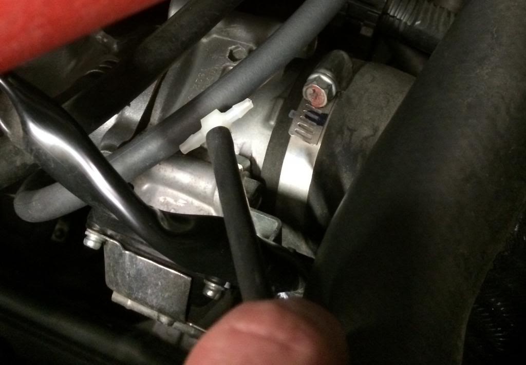
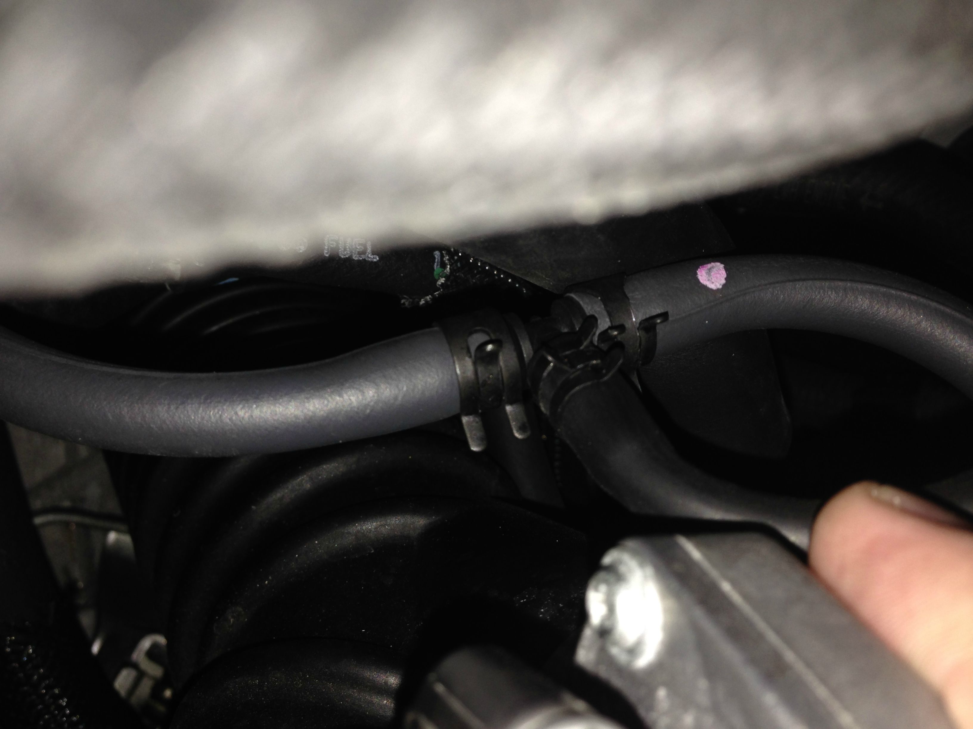
I installed the Defi Advanced CR Boost gauge this weekend, here are a couple things I learned. For one the T fitting supplied doesn’t fit.
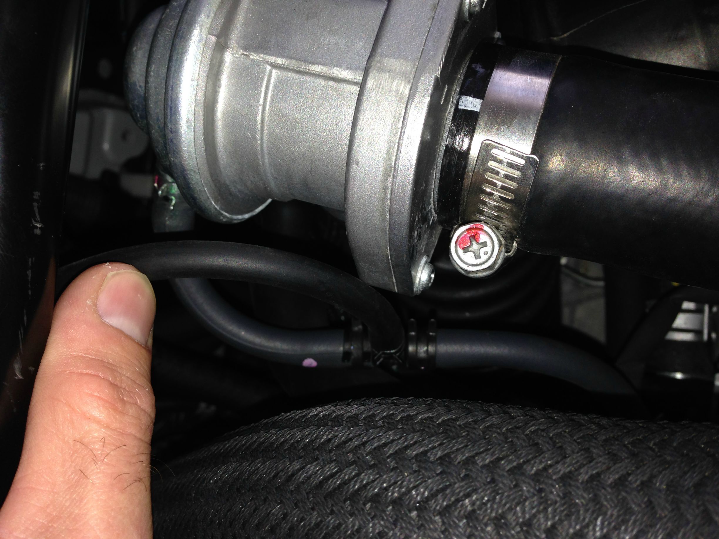
The Evo X vacuum lines up by the BOV are 6mm, and the T fitting is a 4mm (as is the Defi vacuum line).The 4mm felt way to loose in the 6mm hose.

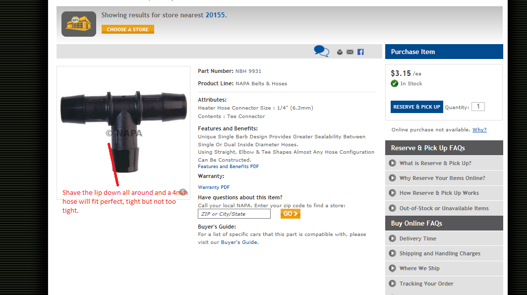
I went to NAPA and got a 1/4 T fitting, and the end that went to the Defi vacuum line I shaved down with a utility razor blade, and it fit just fine.
NAPA also has a package of spring clamps, and those fit nicely on all three sides.
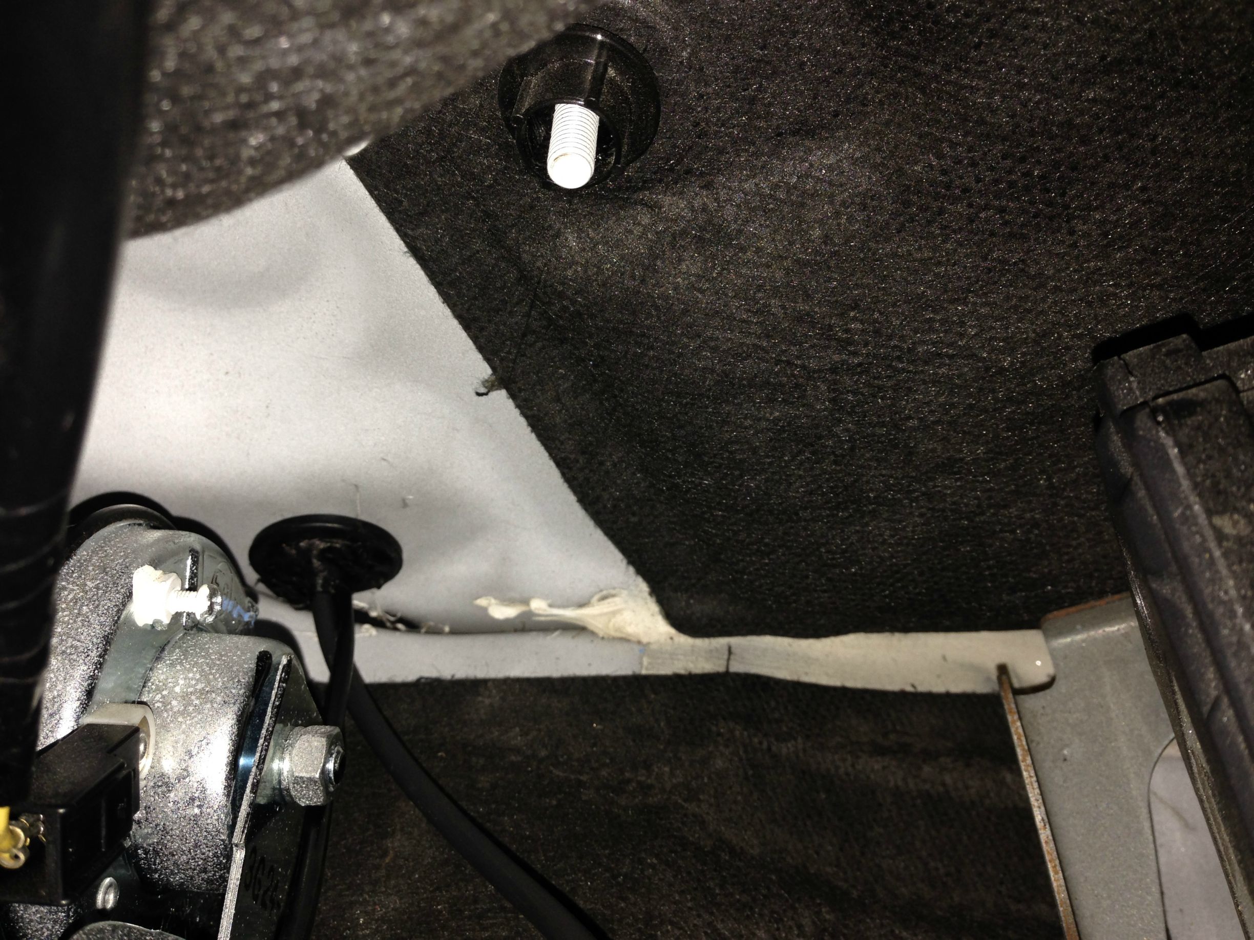
I also bolted the sensor on the firewall like most people do, then I ran it along the front under the heat/sound material (basically the red line on the photo below) (the red circle photo you can see where the connector is for the final cable run) and down into the grommet behind the glove box. That grommet isn’t hard to pull out, or re-install, you just need some long screw drivers. I drilled a hole in the center to fit the line, then dialed in the length, pulled it through from the inside, then went back into the engine bay and seated it.


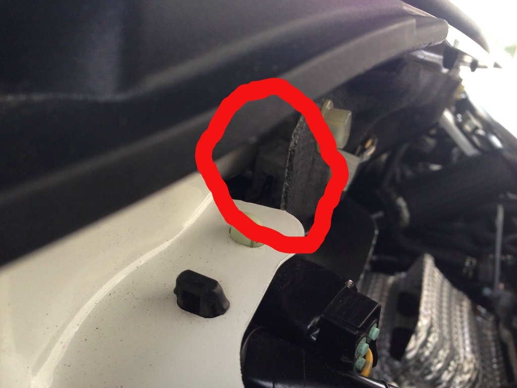
Grommet

NAPA part numbers
705-1300 Hose Corbin Clamp Kit
http://s7d9.scene7.com/is/image/GenuinePartsCompany/NWMDC?$Product=GenuinePartsCompany/1478727

NBH-9931 "1/4 Tee Connector"
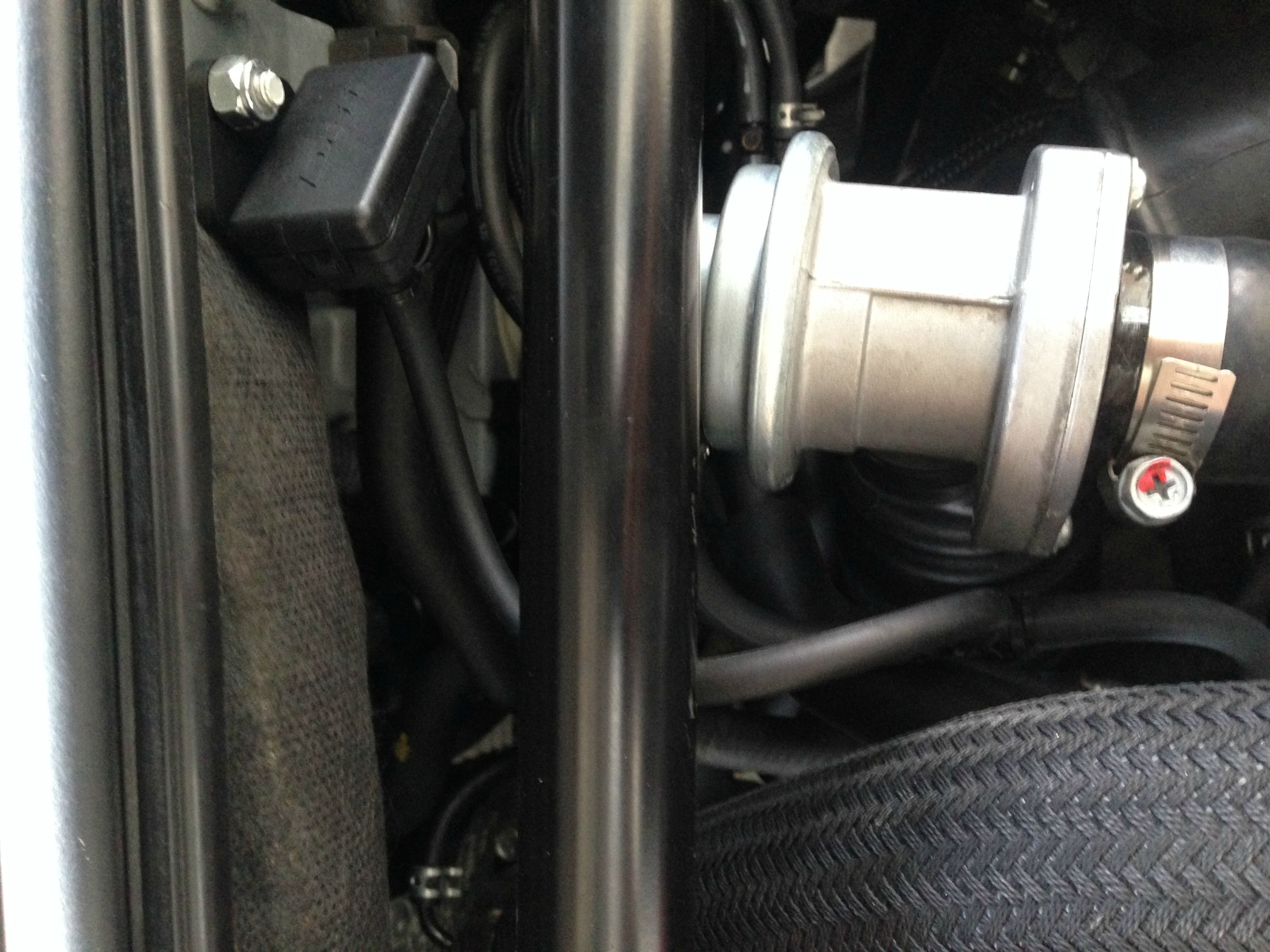
And just for the hell of it, my controller mounting location.

I'm waiting on my Ortiz M45 gauge mount (by the speed-o and tach) to come in so the gauge isn't actually mounted yet, I just did all the pluming this weekend.
Last edited by Psybin; Sep 22, 2014 at 04:45 PM.
