
HOW TO: Install an Apex`i S-AFC

Thread Starter
EvoM Guru
iTrader: (1)
Joined: Mar 2002
Posts: 1,827
Likes: 0
From: From SLO to San Jose
HOW TO: Install an Apex`i S-AFC
WARNING
this is pretty dangerous mod that can kill your engine. i'm not
responsible for anything that may damage your vehicle. it's your
responsibility to do your homework and be confident that you
*know* what you're doing and what this mod entails.
I'm posting this cuz there's a growing number of people
interested in starting to use the S-AFC. Remember, this thing can
blow your engine. It's not as forgiving as a bolt-on mod.
What you're gonna need:
soldering iron
solder
electrical tape
Step 1: Taking off the glove box
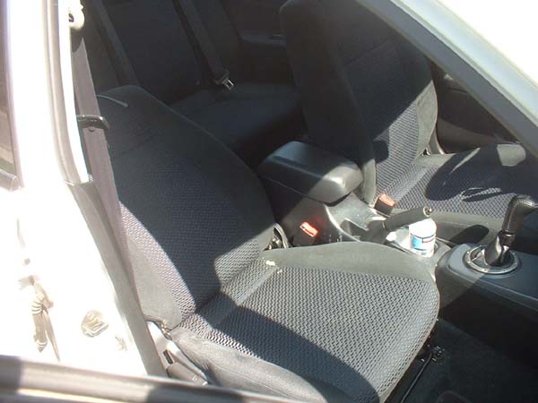
You can put your passenger seat back and recline it all the way
since you're gonna need the room
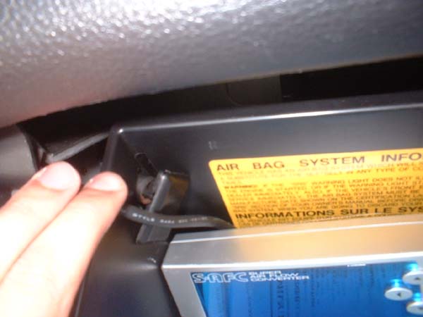
open up your glove box and take this peg out first. just pull
towards you on the peg from outside of the glove box
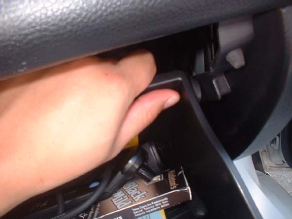
this peg doesn't come off so you're gonna have to tug at the box
until it comes out. Now that the box is loose, just let it swing
down til it's almost upside down and take it off the hinges
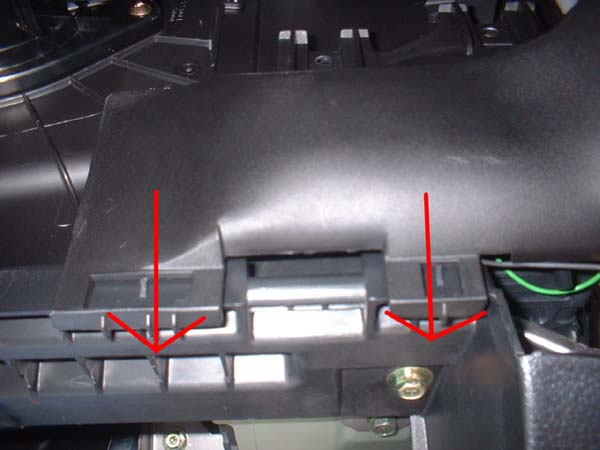
now that you're under the glove box with your legs up the
passenger seat, this is what you should see. just slide the shield
right off towards the passenger seat. simple

now the ecu is exposed. from here, it can go one of two ways.
the manual lancers use a different ecu than the autos. for
reference, the manuals use the Apexi harness diagram for the m3-a,
and the autos use the m7-e. the m3-a has two rows of wires
while the m7-e has 3 rows of wires.
THE M3-A Harness
THE M7-E Harness:

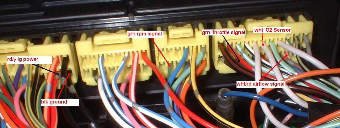
The wire colors should be the same for both auto and manual.
throttle signal - green
airflow signal - white with red stripe
RPM Signal - green with white stripe
Power - red with yellow/orange stripe
Ground - black
O2 sensor - white
if anyone wants to double check, the link is
http://www.twardnw.com/uploads/lancer_wire_diag.pdf
*You really want to check both pin position and wire color as i'm
only certain for the manual ecu's and have never seen what the
auto ecu's look like. For autos, i'm only going on what people
have told me.
So now onto the splicing. all these wires get spliced into, except
for the airflow sensor wire. the airflow wire gets cut.
Splice:
RPM Signal - green with white stripe => Green wire
throttle signal - green => Gray wire
Power - red with yellow/orange stripe => Red wire
Ground - black => Black wire (1-2 inches away from the brown wire and away from the ecu)
=> Brown wire (closer to the ecu but 1-2 inches away from the black wire)
*note: the brown wire is spliced closer to the ecu, while the black
wire is 1-2 inches away from the brown wire. they both splice
into the same black ground wire to the ecu.
O2 sensor - white => Blue Wire (not recommended but can be a
reference voltage to your O2 sensor. in the safc menu, go to ETC
> Sensor check. your o2 voltage will be under In-2. Not
recommened and mythically may damage your ecu. I don't do this.)
*Note: This is also reference for when you get an A/F gauge.
Cut:
Cut the airflow sensor wire completely (white with red stripe).
Solder the pink wire to the wire going to the ecu. Solder the
orange wire to the wire leading back to the MAF sensor.
You're pretty much done! just clean up and wrap all soldering
with electrical tape and put every thing back.
WARNING! This is not a forgiving device!
You can seriously mess up your car with this thing. Do a lot of
homework and really know how fuel injection works. I took a
class and i have a pretty good idea of what i'm doing. Other than
that, HAPPY TUNING
this is pretty dangerous mod that can kill your engine. i'm not
responsible for anything that may damage your vehicle. it's your
responsibility to do your homework and be confident that you
*know* what you're doing and what this mod entails.
I'm posting this cuz there's a growing number of people
interested in starting to use the S-AFC. Remember, this thing can
blow your engine. It's not as forgiving as a bolt-on mod.
What you're gonna need:
soldering iron
solder
electrical tape
Step 1: Taking off the glove box
You can put your passenger seat back and recline it all the way
since you're gonna need the room
open up your glove box and take this peg out first. just pull
towards you on the peg from outside of the glove box
this peg doesn't come off so you're gonna have to tug at the box
until it comes out. Now that the box is loose, just let it swing
down til it's almost upside down and take it off the hinges
now that you're under the glove box with your legs up the
passenger seat, this is what you should see. just slide the shield
right off towards the passenger seat. simple
now the ecu is exposed. from here, it can go one of two ways.
the manual lancers use a different ecu than the autos. for
reference, the manuals use the Apexi harness diagram for the m3-a,
and the autos use the m7-e. the m3-a has two rows of wires
while the m7-e has 3 rows of wires.
THE M3-A Harness
THE M7-E Harness:
The wire colors should be the same for both auto and manual.
throttle signal - green
airflow signal - white with red stripe
RPM Signal - green with white stripe
Power - red with yellow/orange stripe
Ground - black
O2 sensor - white
if anyone wants to double check, the link is
http://www.twardnw.com/uploads/lancer_wire_diag.pdf
*You really want to check both pin position and wire color as i'm
only certain for the manual ecu's and have never seen what the
auto ecu's look like. For autos, i'm only going on what people
have told me.
So now onto the splicing. all these wires get spliced into, except
for the airflow sensor wire. the airflow wire gets cut.
Splice:
RPM Signal - green with white stripe => Green wire
throttle signal - green => Gray wire
Power - red with yellow/orange stripe => Red wire
Ground - black => Black wire (1-2 inches away from the brown wire and away from the ecu)
=> Brown wire (closer to the ecu but 1-2 inches away from the black wire)
*note: the brown wire is spliced closer to the ecu, while the black
wire is 1-2 inches away from the brown wire. they both splice
into the same black ground wire to the ecu.
O2 sensor - white => Blue Wire (not recommended but can be a
reference voltage to your O2 sensor. in the safc menu, go to ETC
> Sensor check. your o2 voltage will be under In-2. Not
recommened and mythically may damage your ecu. I don't do this.)
*Note: This is also reference for when you get an A/F gauge.
Cut:
Cut the airflow sensor wire completely (white with red stripe).
Solder the pink wire to the wire going to the ecu. Solder the
orange wire to the wire leading back to the MAF sensor.
You're pretty much done! just clean up and wrap all soldering
with electrical tape and put every thing back.
WARNING! This is not a forgiving device!
You can seriously mess up your car with this thing. Do a lot of
homework and really know how fuel injection works. I took a
class and i have a pretty good idea of what i'm doing. Other than
that, HAPPY TUNING
Last edited by rhyzin; Jun 30, 2005 at 07:31 PM.
for afc neo only:
*i assume no liability* but this is correct!
green-gray
green w/ white-green
white w/ pink-brown and white to ecu, black and white to maf
red w/ yellow- red
black- black
*i assume no liability* but this is correct!
green-gray
green w/ white-green
white w/ pink-brown and white to ecu, black and white to maf
red w/ yellow- red
black- black

Evolving Member
Joined: Dec 2005
Posts: 302
Likes: 0
From: MidWest
yah, I still don't know how the heck to wire mine for an auto 2005 es.
edit: ok I get it. The m7 was switched to the 6 (the one above).
\Here's another dumb question. When he says splice (e.g. green wire (safc) to green and white wire (car) is he wanting us to TAP into that ecu wire? I would think that's what it is, because if you cut the ecu wire and then spliced the two, wouldn't your rpm guage not work on the dash? I'm strugglin' here. I have located the first two wires to be spliced. I know how to solder. My thinking is I should tap into the ecu wires, for all those that don't say CUT. correct?
Man is there anyone around Orlando who could help me out with this?
Last edited by newbiewonkenobe; Aug 13, 2006 at 12:49 PM.
Thread Starter
EvoM Guru
iTrader: (1)
Joined: Mar 2002
Posts: 1,827
Likes: 0
From: From SLO to San Jose
yeah, by SPLICE, i mean TAP. means the same to me.
the wiring diagram codes by apexi don't seem to roll over to the next year. i also use the jdm diagrams and photoshop over the japanese writing. i check them against the wiring diagrams from the shop manual i have.
there are a bunch of mirage guys in florida that could more than help you out there. dunno if they'd see this thread tho.
Evolving Member
Joined: Dec 2005
Posts: 302
Likes: 0
From: MidWest
Rhyzin - I only ask 'cause I don't know crap about electrical terms. Wasn't trying to be a wise guy  . Thanks for the how-to and for clarifying it for me. Looking to install my SAFC-II probably tomorrow evening.

. Thanks for the how-to and for clarifying it for me. Looking to install my SAFC-II probably tomorrow evening.
Trending Topics

Thread
Thread Starter
Forum
Replies
Last Post
Evo_Jay
For Sale/WTB - Engine / Drivetrain / Power
7
Feb 7, 2007 07:21 PM