
HOW TO: Install ebay fog lights

Thread Starter
Evolved Member
Joined: Jan 2008
Posts: 614
Likes: 1
From: North NJ
HOW TO: Install ebay fog lights
Tools and Materials:
-Fog light kit
-A ratchet + extension + 10 mm and 12 mm sockets
-Philips screwdriver
-Pliers
-Coat hanger or similar wire
-[Optional] Drill & Drill bit set
This will be a step by step guide of the installation of the "OEM Style" fog lights commonly sold on e-bay and autocityimports.com.
I'm going to explain two different possibilities:
Option 1: The fog lights are going to be wired in such a way that they will be controlled by a switch (included with the kit).
You can't forget the fog lights turned on because the relay will take the signal from a switched power source.
Pros: Full control
Cons: Harder + longer installation.
Option 2: The fog lights are going to be wired in such a way that the fog lights will turn on with the parking lights, when the switch is on position 1 and 2 with the side markers, low beams and/or high beams.
Pros: Easy installation, no need for a switch, no need to take wires through the firewall.
Cons: Lack of control
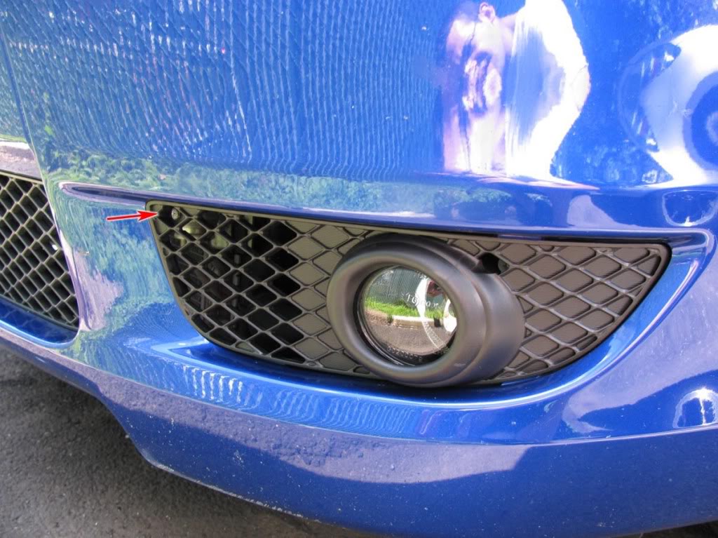
OPTION 1:
Step 1
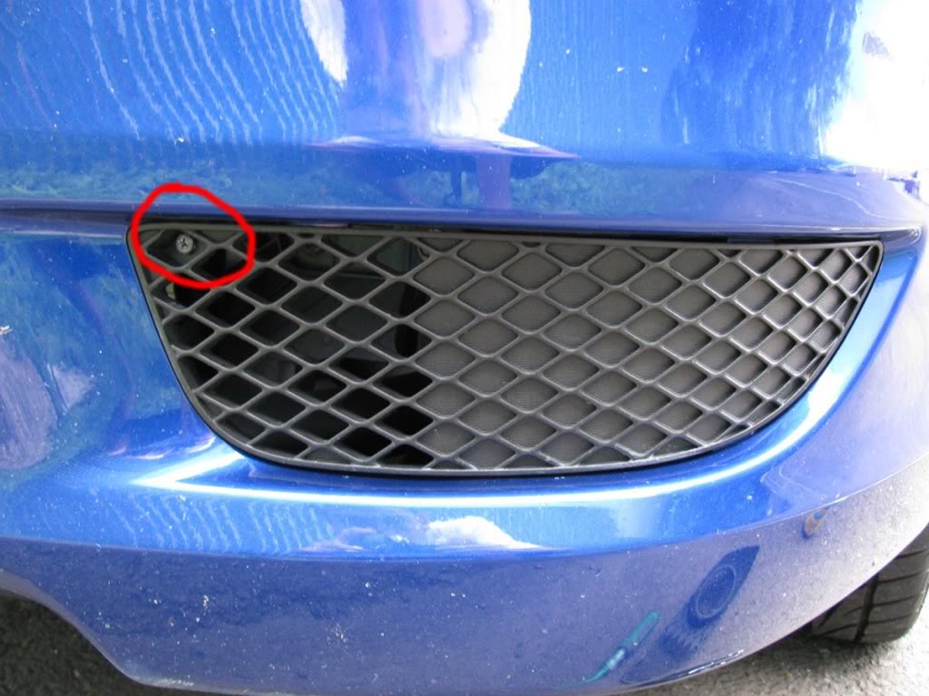
Take of the existing plastic bezel. It's held in place by 1 screw. Repeat this on the other side.
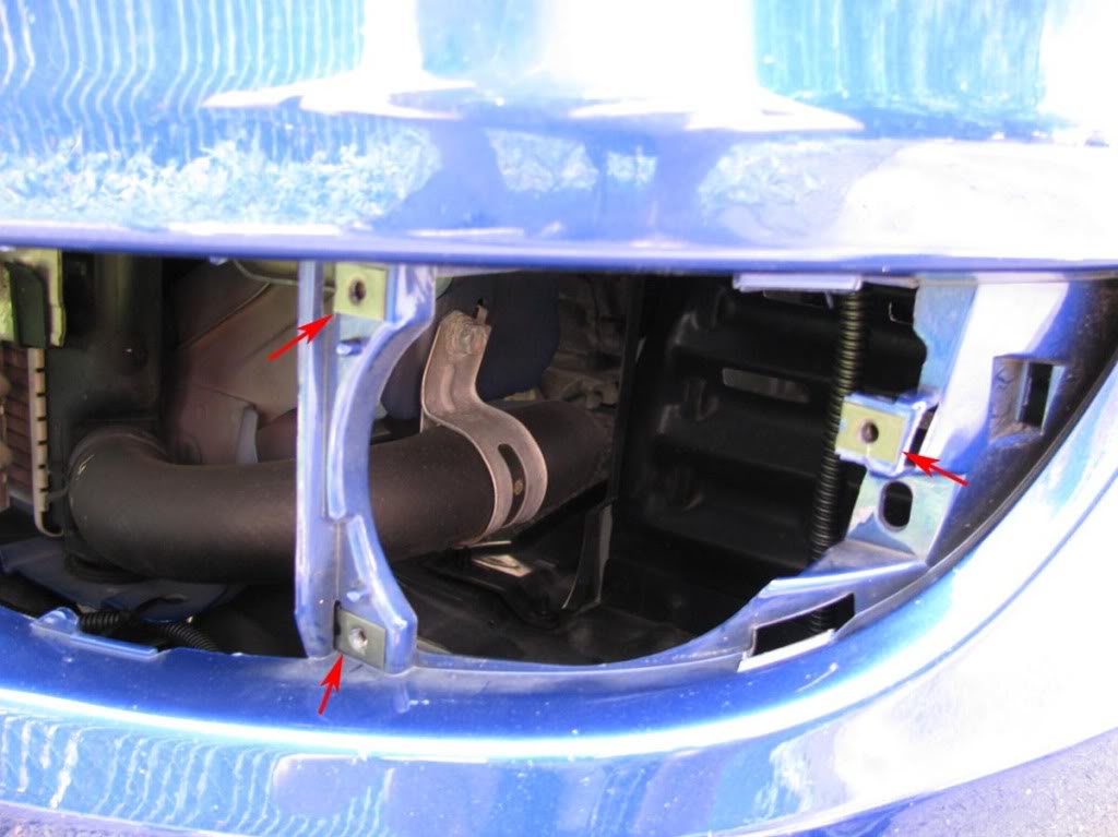
Step 2
Slide 3 polygon clips over the 3 holes. Repeat this on the other side.
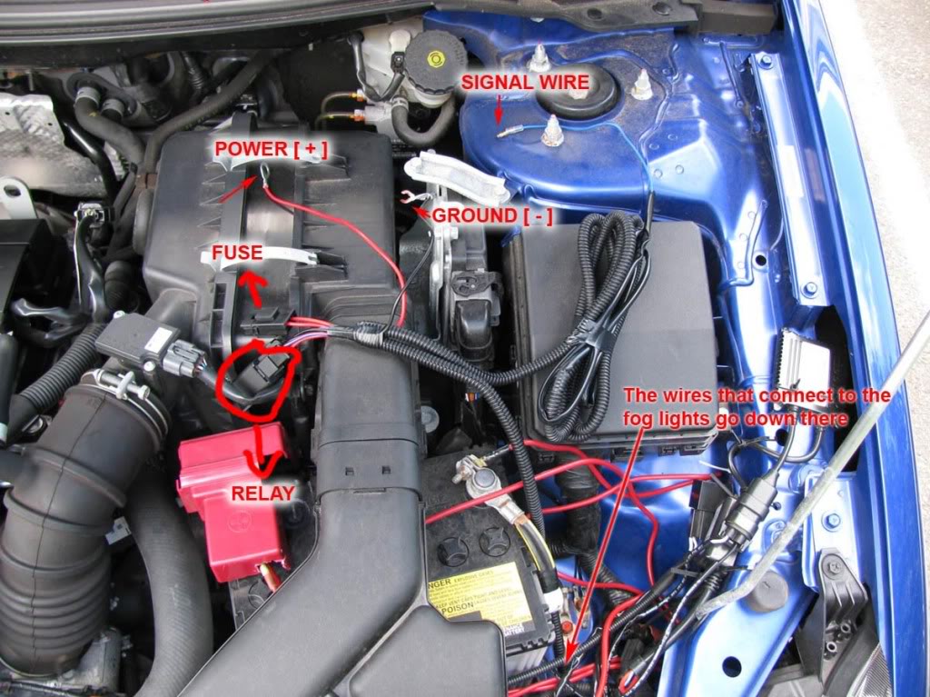
Step 3
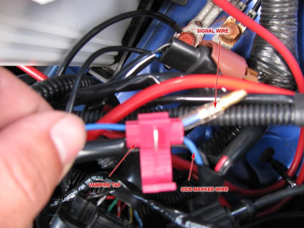
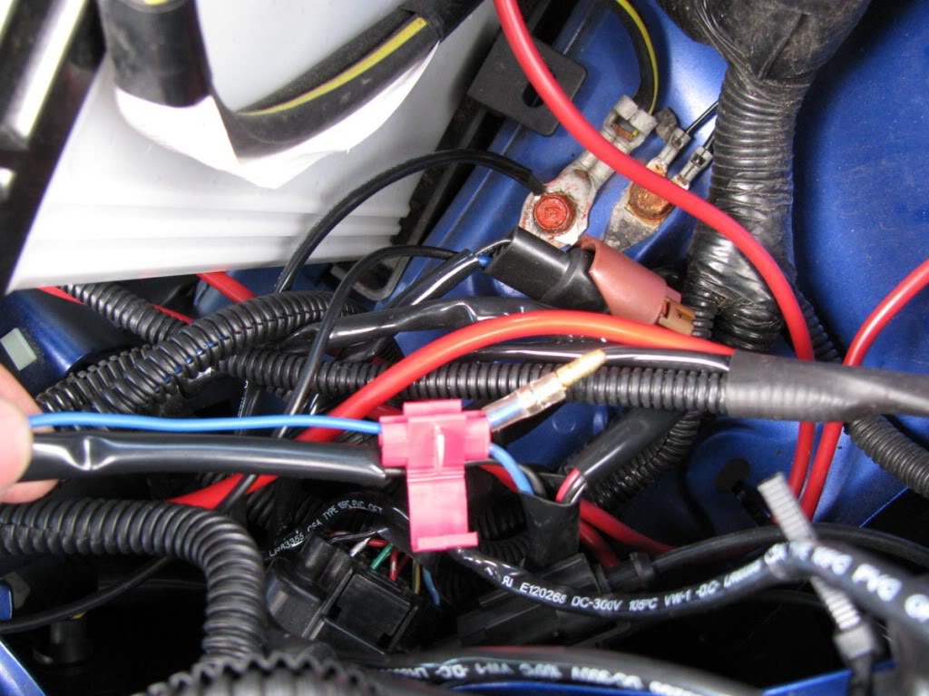
Spread the main harness and become familiar with the components and their names.
Refer to this picture:
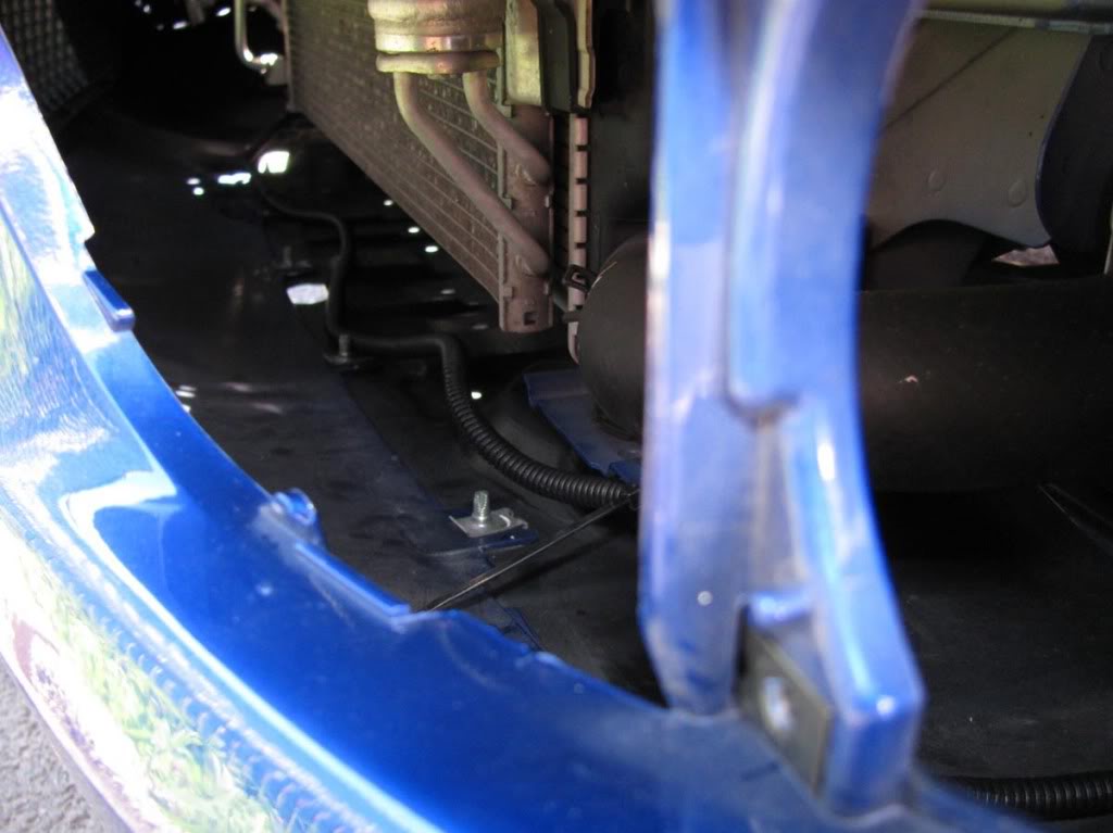
Run the two H11 connectors (they connect to the back of the fog light bulbs) from the right side of the battery, down to the fog light holes.
Refer to these pictures:
Step 4
Connect the H11 plug to the fog light assembly.
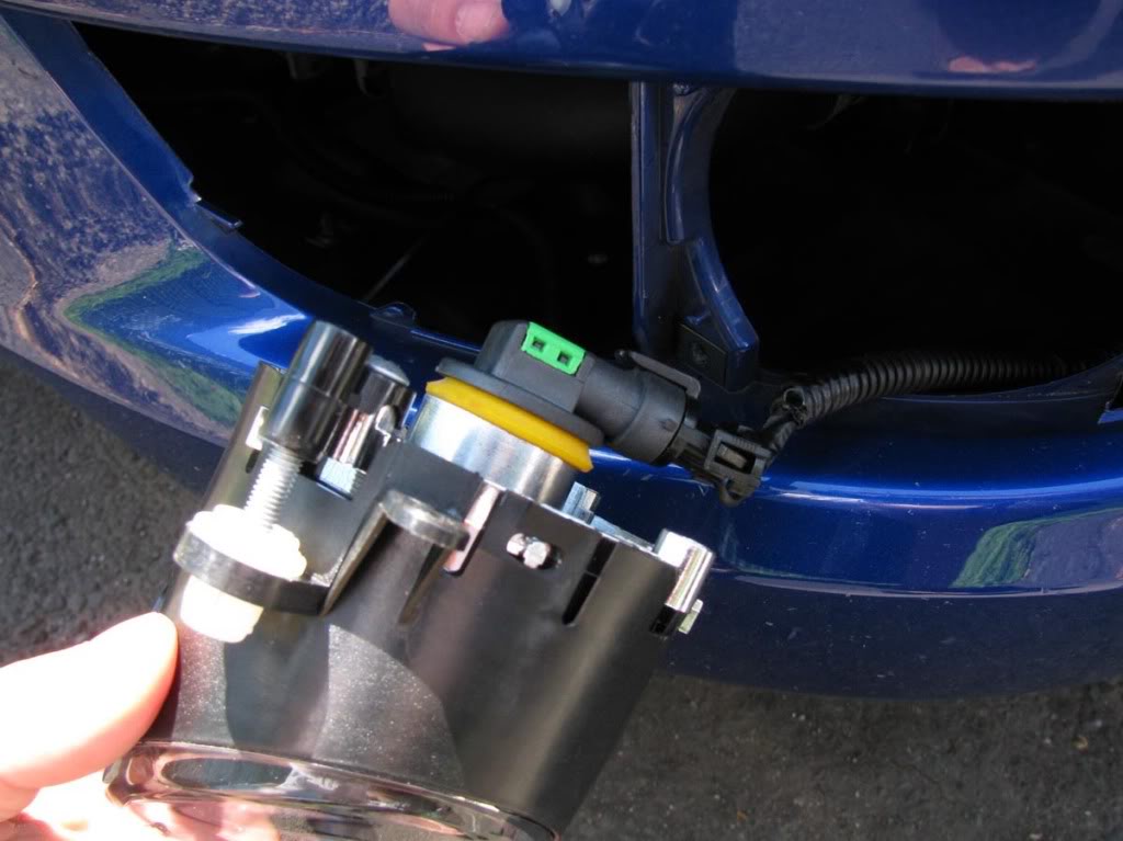
Mount the fog light assembly using 3 of the provided screws. [Note the adjustment screw in the picture; you might want to use it in the end]
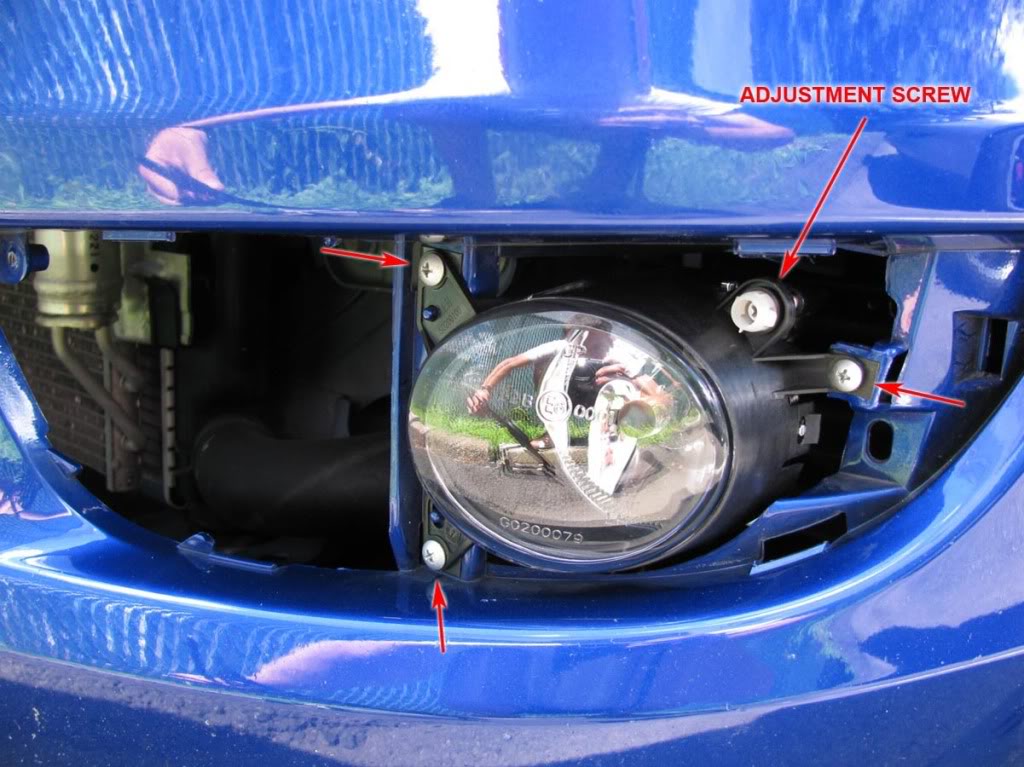
Then mount the new plastic bezel using 1 screw.
Repeat this for the other side.
Step 5
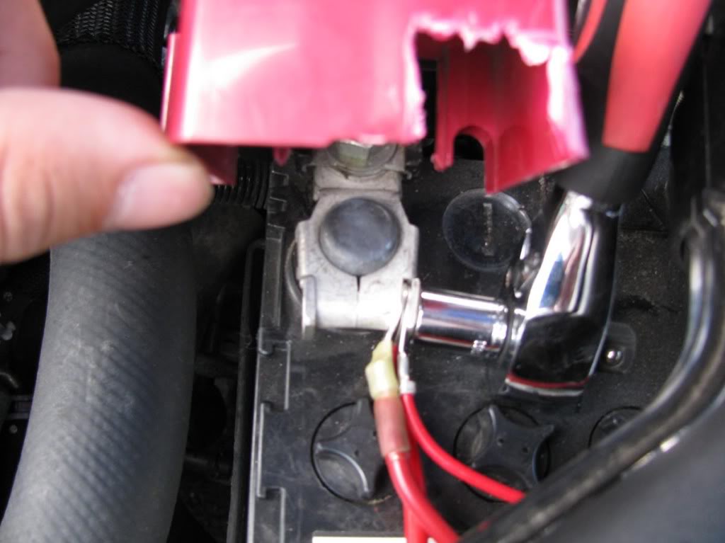
Using a ratchet with a 10 mm socket, connect the red power wire to the POSITIVE terminal of the battery.
You might need to cut the red terminal cover a little like in the photo.
Step 6
Using a ratchet with an extension and a 10 mm socket, connect the black ground wire to one of the bolts on the right side of the battery.
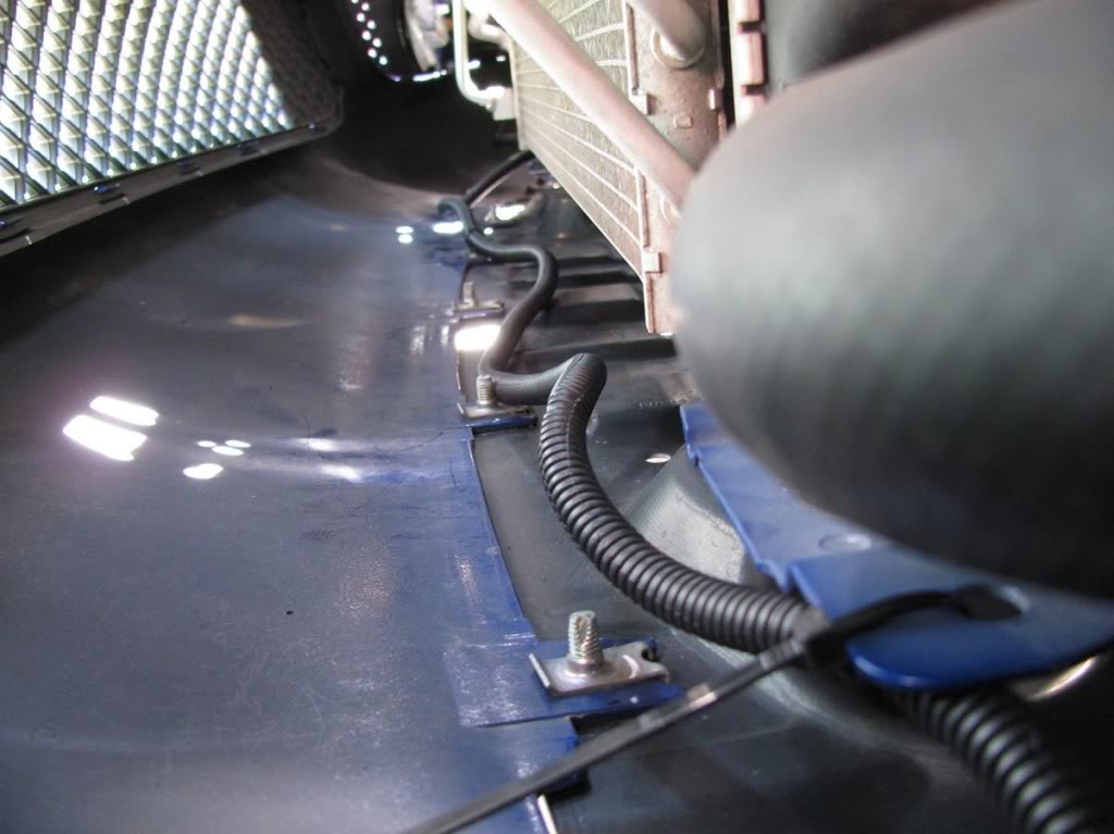
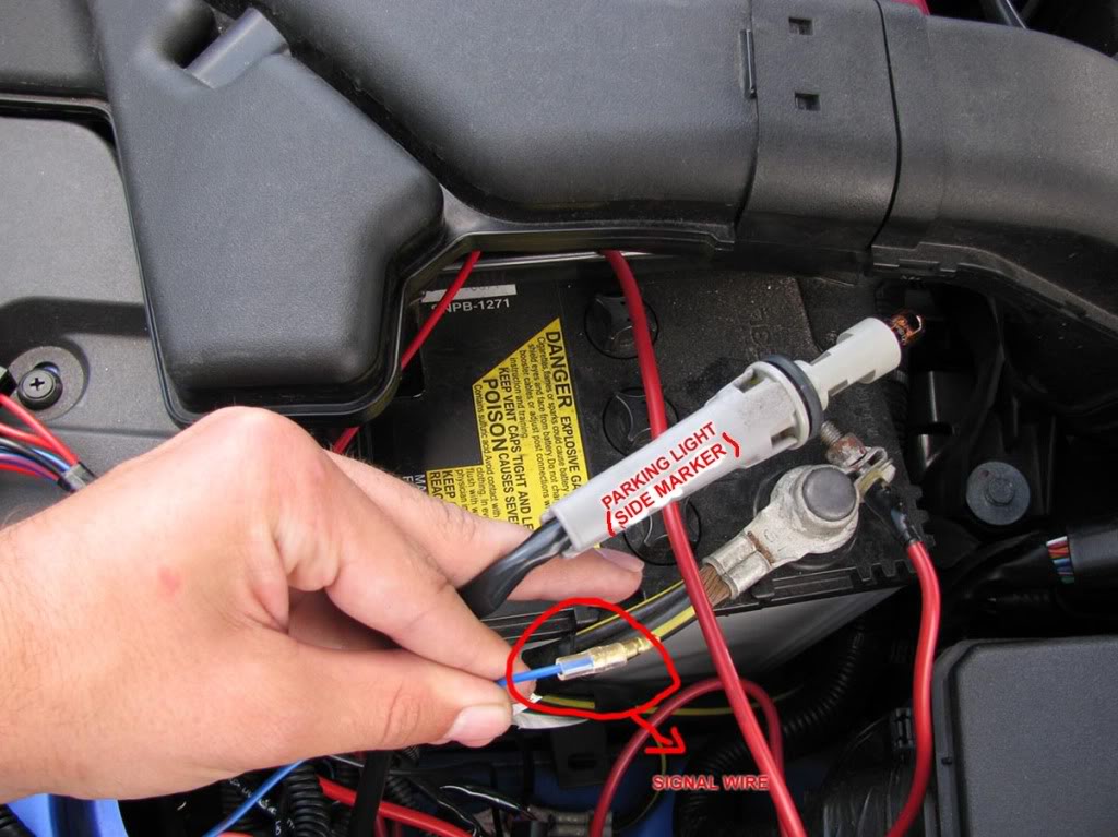
Step 7
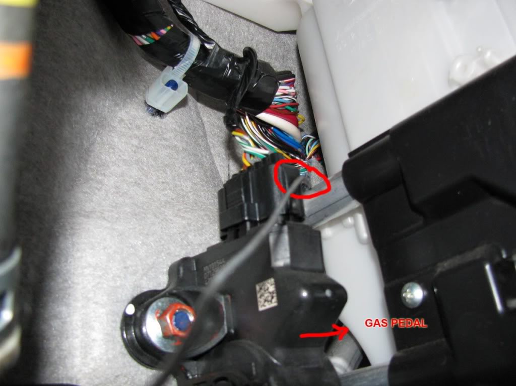
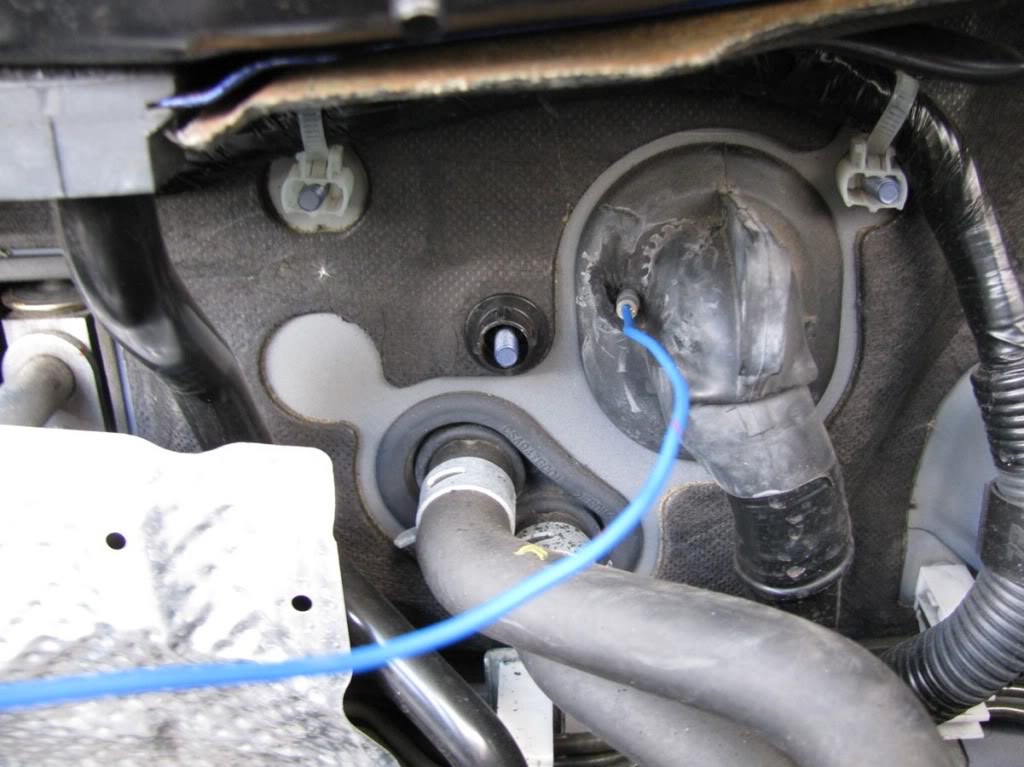
Now comes the annoying part. We need to pass the blue signal wire through the firewall.
We will create a hole in the big black rubber insulator.
It's time to straighten the coat hanger and poke a hole on the insulator.
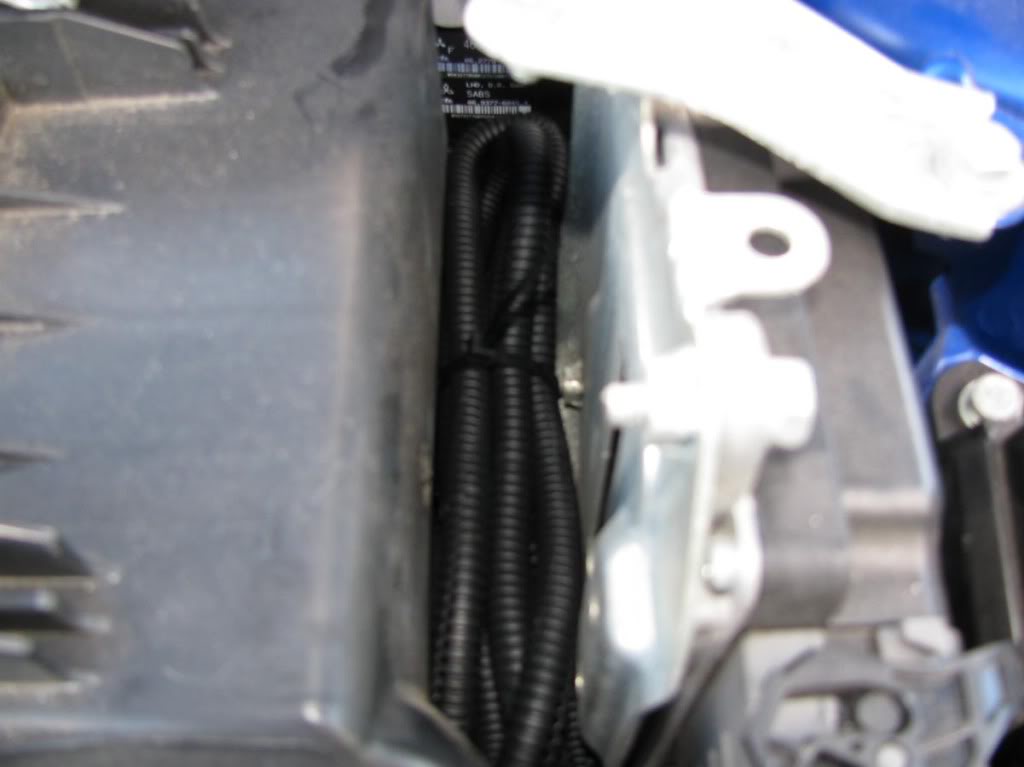
***Note: Once you made the hole, push the wire WITH MINIMUM PRESSURE and try to take it to the other side. The last thing you want is to damage the existing wires.
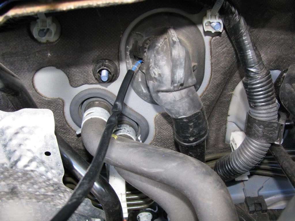
The wire should exit in the location circled in the picture below.
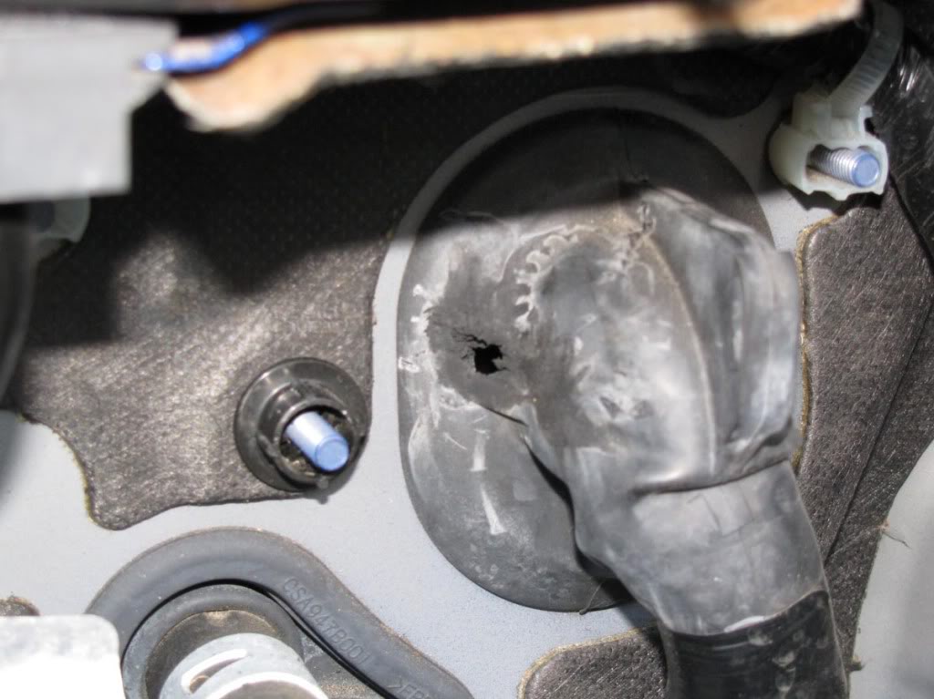
Now we need to make the hole a little bigger. I used a drill with a relatively thick drill bit and pliers to rip the rubber chunks off.
****If you use a drill bit remember to use the TIP ONLY. Do not go deep or you'll damage the wires!
Here's what you should have:
Step 8
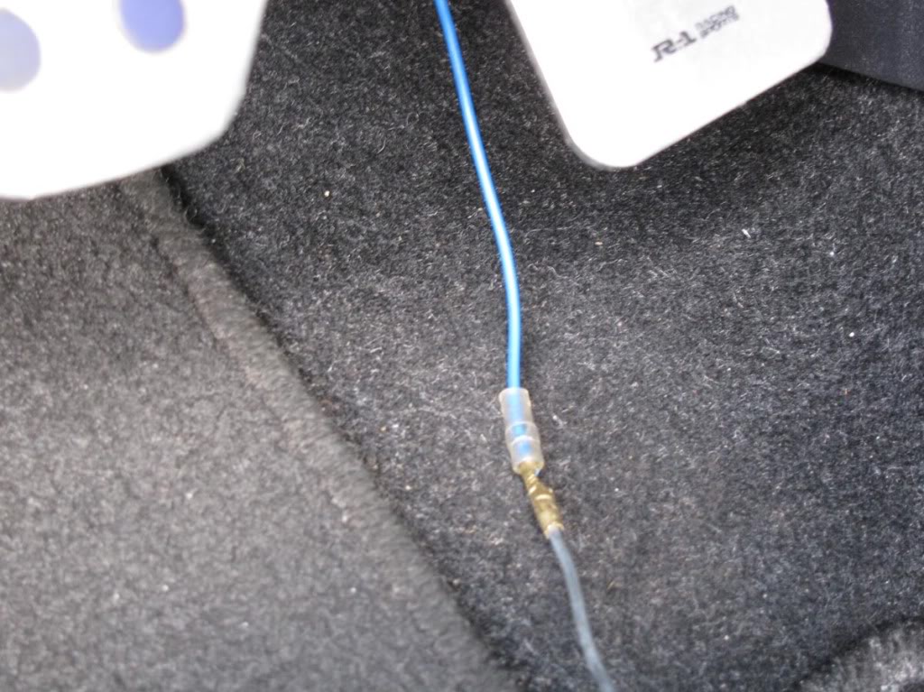
Now it's time to pull the blue signal wire through the hole. Secure the connector of the blue wire to the coat hanger.
Refer to this picture:
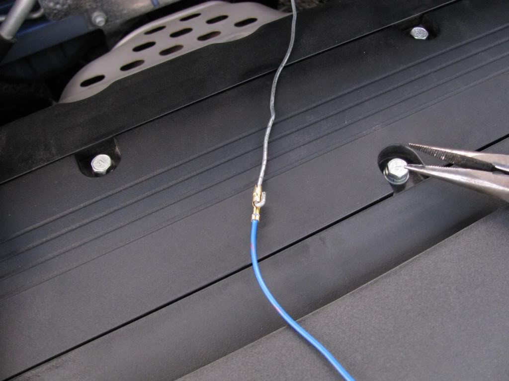
Before you pull it to the other side, remove about 1.5 ft of the black insulator around the blue wire.
You will go from this:
To this:
Now pull it through.
Step 9
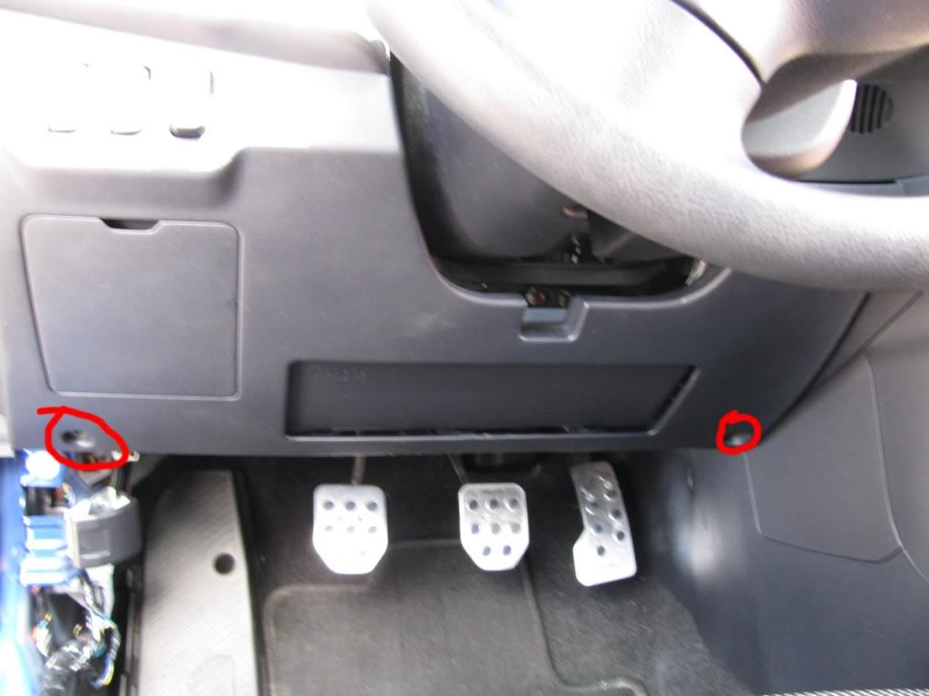
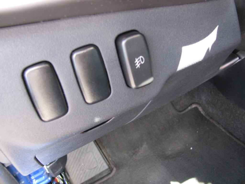
We need to take out one of the blank switches and install our switch.
To remove one of the blank switches you need to remove the panel that is located below the steering wheel.
Remove the 2 screws at the bottom and also pop a bunch of clips on the top.
On the back of the panel there is a piece of plastic that secures the switches. It is held by 3 screws.
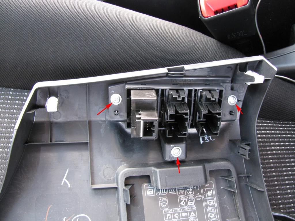
Remove the blank switch and put the provided switch in its place. Leave that panel aside and take a look at your switch wiring harness.
Step 10
Wiring the switch harness.
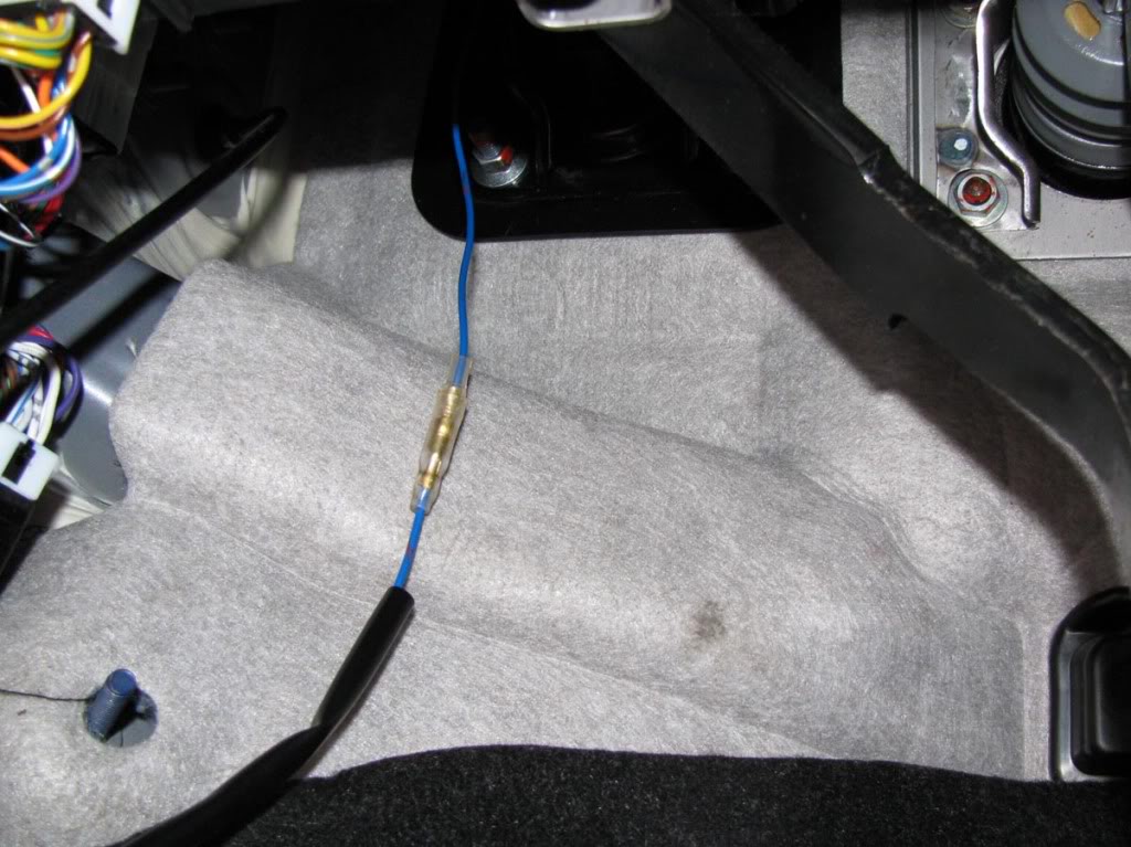
First get familiar with it. Here it is:
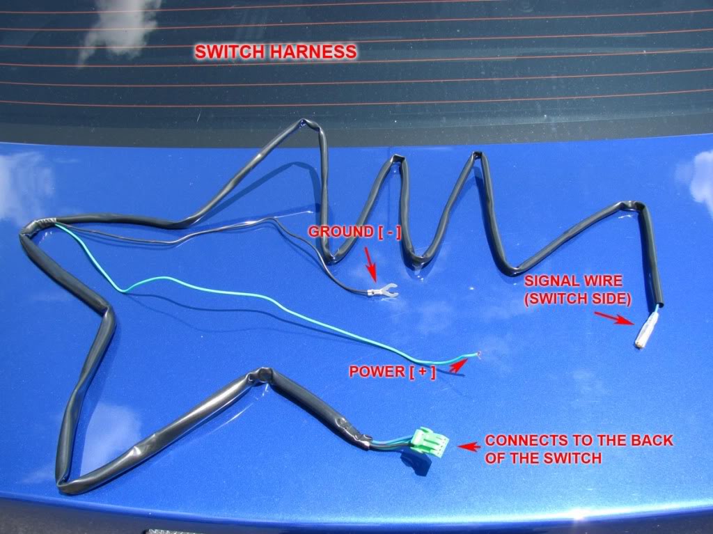
Connect the blue signal wire that we brought from the engine compartment to the blue signal wire on the switch harness.
Make sure you pass the wires over the pedals.
Step 11
Strip the power wire (+) about 1 cm. We will connect the power wire to a switched power source that only works with the key inside in position 1 or 2.
Remove fuse #14 inside the cabin by using the fuse puller found inside the fuse box in the engine compartment.
It's a 10A ignition switch fuse.
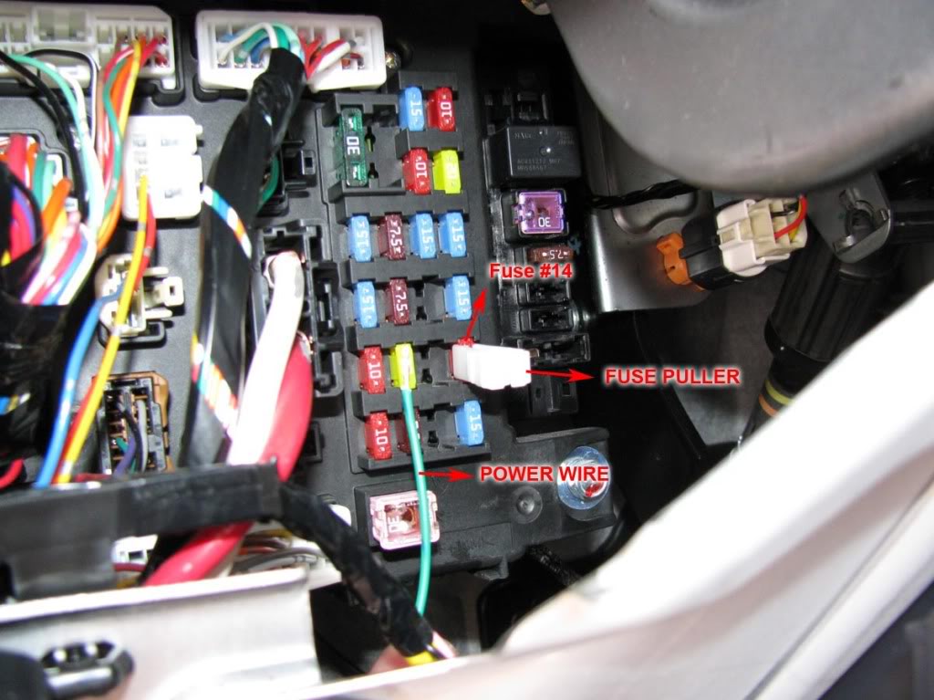
Insert the power wire and put the fuse over it.
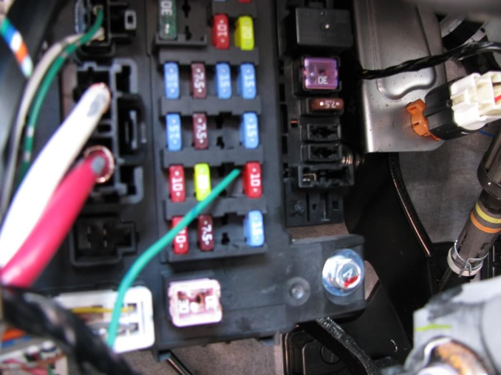
Step 12
Use a 12mm socket to loosen the bolt show in the picture below.
Connect the ground terminal to that bolt.
***Note: You might need to make the terminal opening a little wider to make it fit.
Step 13
The wiring harness is longer than it needs to be.
Use zip ties to organize it.
Step 14
Plug the remaining green connector to the back of the switch.
Mount the panel again by aligning + pushing the clips first and then using the 2 screws on the bottom.
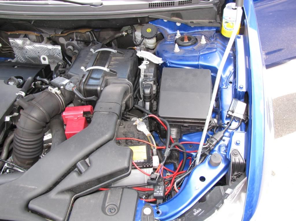
Step 15
Almost done! Put the key in the ignition and turn it once. Press the fog light switch and they should work.
If they don't work please review the steps to make sure that everything is plugged in.
Now it's time to make everything look tidy.
Use plenty of zip ties. Make sure that the blue wire is not hanging on top of the exhaust manifold or it might get burned.
Tuck in the rest of the harness in between the filter box and the ECU.
Inside the cabin, make sure that the wiring is out of the way of the pedals.
OPTION 2:
Steps 1 - 6 are the same as above.
Step 7
Remove the driver's side side marker.
Step 8
We are gonna tap into the side marker wire using a t-tap or vampire tap.
The idea is to connect the signal wire to the side marker wire so that every time the side marker is turned on, the signal wire signals the relay to close the circuit (turn on the fog lights).
Step 9
That's it. Make sure you use zip ties to organize the wiring (refer to step 15 of option 1).
Turn on your lights. Your fog lights should also turn on.
That's it. Remember, just post a comment if you have any questions.
I hope the instructions are clear and easy to follow.
Have fun!
MasterAK
[img][/img]
-Fog light kit
-A ratchet + extension + 10 mm and 12 mm sockets
-Philips screwdriver
-Pliers
-Coat hanger or similar wire
-[Optional] Drill & Drill bit set
This will be a step by step guide of the installation of the "OEM Style" fog lights commonly sold on e-bay and autocityimports.com.
I'm going to explain two different possibilities:
Option 1: The fog lights are going to be wired in such a way that they will be controlled by a switch (included with the kit).
You can't forget the fog lights turned on because the relay will take the signal from a switched power source.
Pros: Full control
Cons: Harder + longer installation.
Option 2: The fog lights are going to be wired in such a way that the fog lights will turn on with the parking lights, when the switch is on position 1 and 2 with the side markers, low beams and/or high beams.
Pros: Easy installation, no need for a switch, no need to take wires through the firewall.
Cons: Lack of control
OPTION 1:
Step 1
Take of the existing plastic bezel. It's held in place by 1 screw. Repeat this on the other side.
Step 2
Slide 3 polygon clips over the 3 holes. Repeat this on the other side.
Step 3
Spread the main harness and become familiar with the components and their names.
Refer to this picture:
Run the two H11 connectors (they connect to the back of the fog light bulbs) from the right side of the battery, down to the fog light holes.
Refer to these pictures:
Step 4
Connect the H11 plug to the fog light assembly.
Mount the fog light assembly using 3 of the provided screws. [Note the adjustment screw in the picture; you might want to use it in the end]
Then mount the new plastic bezel using 1 screw.
Repeat this for the other side.
Step 5
Using a ratchet with a 10 mm socket, connect the red power wire to the POSITIVE terminal of the battery.
You might need to cut the red terminal cover a little like in the photo.
Step 6
Using a ratchet with an extension and a 10 mm socket, connect the black ground wire to one of the bolts on the right side of the battery.
Step 7
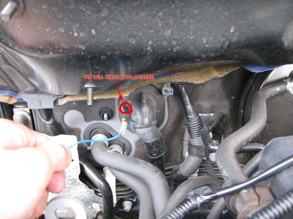
Now comes the annoying part. We need to pass the blue signal wire through the firewall.
We will create a hole in the big black rubber insulator.
It's time to straighten the coat hanger and poke a hole on the insulator.
***Note: Once you made the hole, push the wire WITH MINIMUM PRESSURE and try to take it to the other side. The last thing you want is to damage the existing wires.
The wire should exit in the location circled in the picture below.
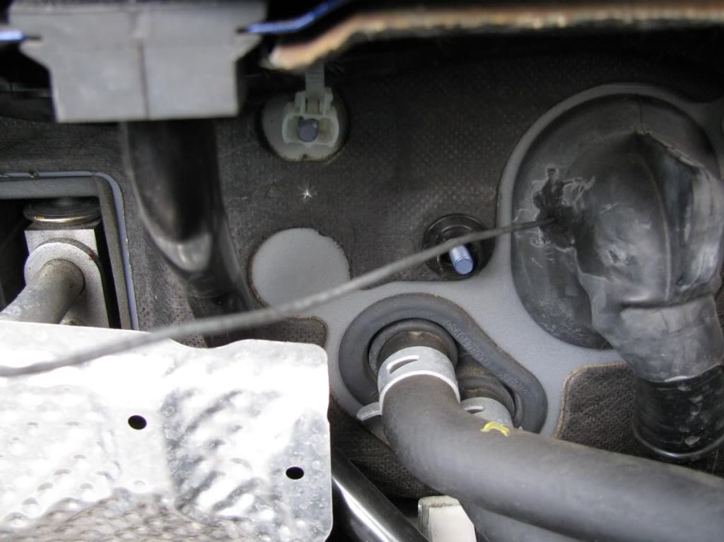
Now we need to make the hole a little bigger. I used a drill with a relatively thick drill bit and pliers to rip the rubber chunks off.
****If you use a drill bit remember to use the TIP ONLY. Do not go deep or you'll damage the wires!
Here's what you should have:
Step 8
Now it's time to pull the blue signal wire through the hole. Secure the connector of the blue wire to the coat hanger.
Refer to this picture:
Before you pull it to the other side, remove about 1.5 ft of the black insulator around the blue wire.
You will go from this:
To this:
Now pull it through.
Step 9
We need to take out one of the blank switches and install our switch.
To remove one of the blank switches you need to remove the panel that is located below the steering wheel.
Remove the 2 screws at the bottom and also pop a bunch of clips on the top.
On the back of the panel there is a piece of plastic that secures the switches. It is held by 3 screws.
Remove the blank switch and put the provided switch in its place. Leave that panel aside and take a look at your switch wiring harness.
Step 10
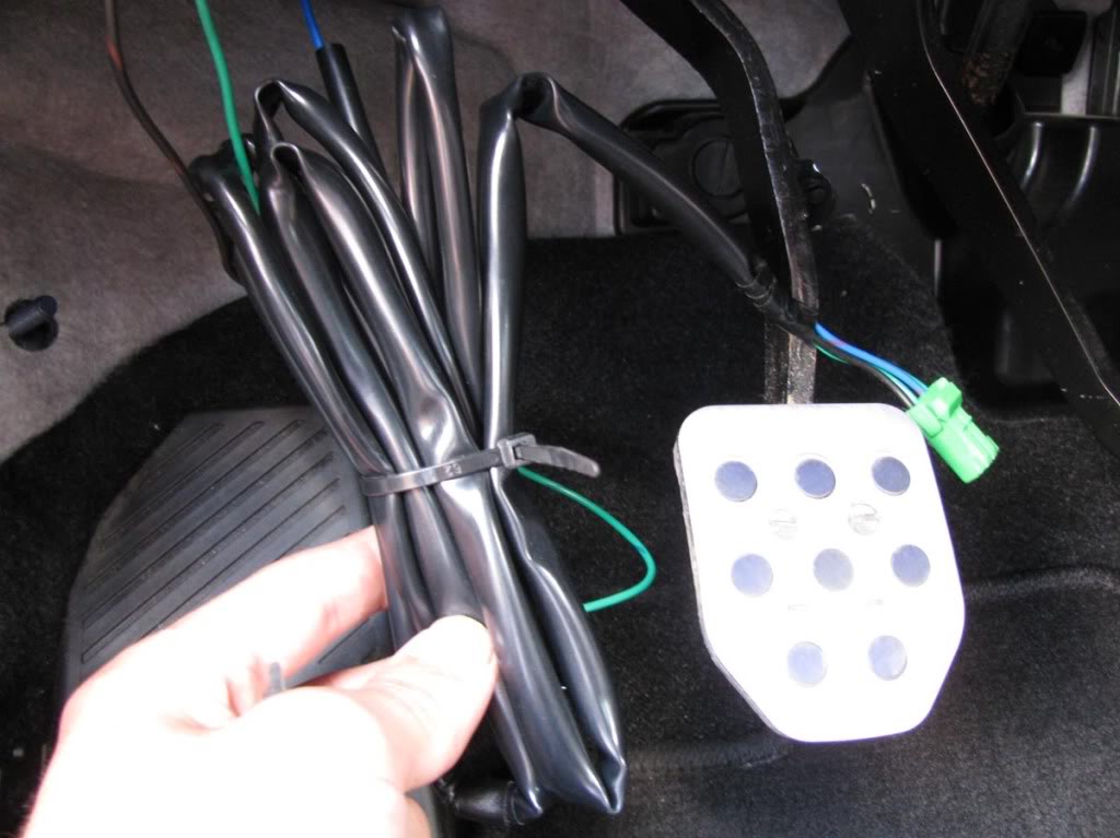
Wiring the switch harness.
First get familiar with it. Here it is:
Connect the blue signal wire that we brought from the engine compartment to the blue signal wire on the switch harness.
Make sure you pass the wires over the pedals.
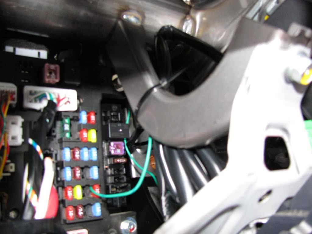
Step 11
Strip the power wire (+) about 1 cm. We will connect the power wire to a switched power source that only works with the key inside in position 1 or 2.
Remove fuse #14 inside the cabin by using the fuse puller found inside the fuse box in the engine compartment.
It's a 10A ignition switch fuse.
Insert the power wire and put the fuse over it.
Step 12
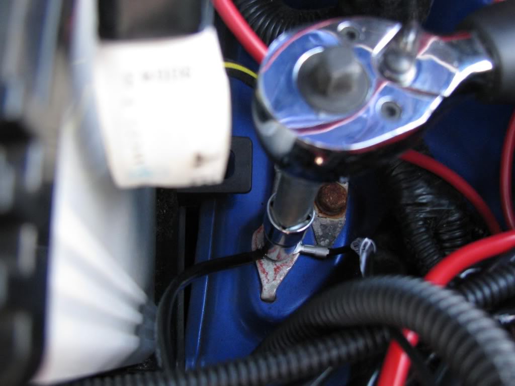
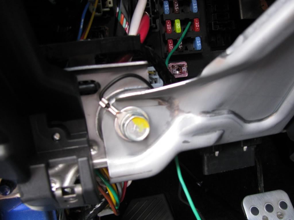
Use a 12mm socket to loosen the bolt show in the picture below.
Connect the ground terminal to that bolt.
***Note: You might need to make the terminal opening a little wider to make it fit.
Step 13
The wiring harness is longer than it needs to be.
Use zip ties to organize it.
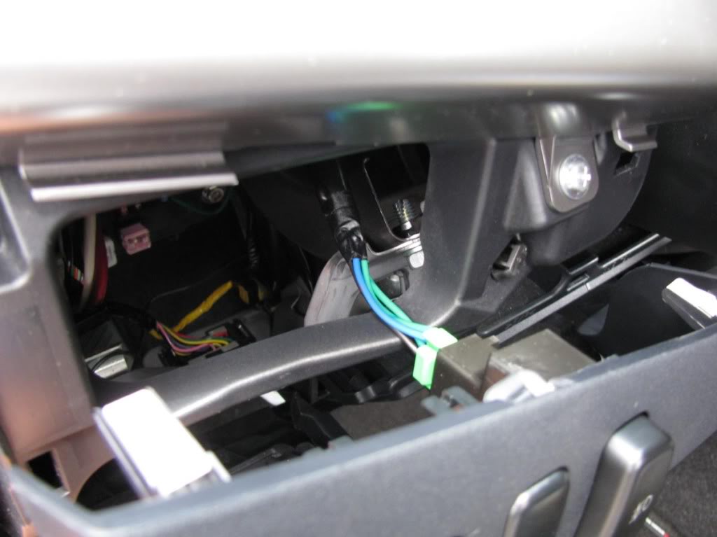
Step 14
Plug the remaining green connector to the back of the switch.
Mount the panel again by aligning + pushing the clips first and then using the 2 screws on the bottom.
Step 15
Almost done! Put the key in the ignition and turn it once. Press the fog light switch and they should work.
If they don't work please review the steps to make sure that everything is plugged in.
Now it's time to make everything look tidy.
Use plenty of zip ties. Make sure that the blue wire is not hanging on top of the exhaust manifold or it might get burned.
Tuck in the rest of the harness in between the filter box and the ECU.
Inside the cabin, make sure that the wiring is out of the way of the pedals.
OPTION 2:
Steps 1 - 6 are the same as above.
Step 7
Remove the driver's side side marker.
Step 8
We are gonna tap into the side marker wire using a t-tap or vampire tap.
The idea is to connect the signal wire to the side marker wire so that every time the side marker is turned on, the signal wire signals the relay to close the circuit (turn on the fog lights).
Step 9
That's it. Make sure you use zip ties to organize the wiring (refer to step 15 of option 1).
Turn on your lights. Your fog lights should also turn on.
That's it. Remember, just post a comment if you have any questions.
I hope the instructions are clear and easy to follow.
Have fun!
MasterAK
[img][/img]
Last edited by MasterAK; Jul 5, 2009 at 05:43 PM.
Evolving Member
Joined: Jun 2007
Posts: 122
Likes: 0
From: Toronto, ON
You got the OE Replicas right. Did your Car throw a CEL when you hooked up the relay?
Wierd thing is I had the OEM fog's till one of the glass housings shattered, Not covered by warranty, Picked up a set of the replicas for the housing. (Whole set was cheaper than buying one OEM Replacement housing)
I wanted to use the switch that came with them and the fog light switch on the original signal stock for the HID's, But when I wired the relay kit supplied the car went limp and threw a CEL. But the lights worked.
I removed the harness supplied and rehooked it to the OEM signal stock for fogs
Long story short, I'm not asking for a fix just wondering if yours did the same.
Thread Starter
Evolved Member
Joined: Jan 2008
Posts: 614
Likes: 1
From: North NJ
You got the OE Replicas right. Did your Car throw a CEL when you hooked up the relay?
Wierd thing is I had the OEM fog's till one of the glass housings shattered, Not covered by warranty, Picked up a set of the replicas for the housing. (Whole set was cheaper than buying one OEM Replacement housing)
I wanted to use the switch that came with them and the fog light switch on the original signal stock for the HID's, But when I wired the relay kit supplied the car went limp and threw a CEL. But the lights worked.
I removed the harness supplied and rehooked it to the OEM signal stock for fogs
Long story short, I'm not asking for a fix just wondering if yours did the same.
Wierd thing is I had the OEM fog's till one of the glass housings shattered, Not covered by warranty, Picked up a set of the replicas for the housing. (Whole set was cheaper than buying one OEM Replacement housing)
I wanted to use the switch that came with them and the fog light switch on the original signal stock for the HID's, But when I wired the relay kit supplied the car went limp and threw a CEL. But the lights worked.
I removed the harness supplied and rehooked it to the OEM signal stock for fogs
Long story short, I'm not asking for a fix just wondering if yours did the same.
Evolving Member
Joined: Jun 2007
Posts: 122
Likes: 0
From: Toronto, ON
that's what im saying its not possible to throw a CEL. The relay was wired the same just to the fogs. When I took the harness of it was fine, No matter which way i installed CEL. Meh I did figure something out so this in not an issue anymore.


Trending Topics

Newbie
Joined: Nov 2010
Posts: 5
Likes: 0
From: PA
Got my fog lights yesterday, installing today. One question.
For connecting the ground wire in the engine compartment, I do not have a 10mm ratchet, so its hard for me to attach the wire to the area shown in the picture.
This may be a stupid question, but I am thinking of attaching the wire to one of the bolts for the headlights. The headlight has a plastic piece, and the bolt goes through that into the metal of the engine compartment. I loosened that bolt, and slipped the wire underneath the plastic part so that it is resting on the metal, and it gets fastened down to that area by re-tightening the bolt.
My question is- Is this an acceptable location for the ground wire? I really know nothing about electrical so Im wondering if it matters that it is in contact with plastic as well as metal. Is this alright, or does it have to be only metal?
In the picture of the engine compartment corresponding to step 15, you can see the part of the headlight assembly that I am talking about.
Last edited by JRATC; Dec 3, 2010 at 01:11 PM.
Newbie
Joined: Nov 2010
Posts: 5
Likes: 0
From: PA
Thanks for your response. And thank you to everyone in these forums. Especially MasterAK for taking the time to post these pictures and instructions.
However, I finished the job, and unfortunately they dont work. The switch itself lights up inside the car, but no luck with the actual lights.
I went through checking every connection, also made sure the fuse is still good where the fuse wire plugs in, and I cant figure out what is wrong. I guess Ill be paying for installation after all.
Newbie
Joined: Nov 2010
Posts: 5
Likes: 0
From: PA
After the lights didnt work I found my switch was faulty. Copper on the circuit board actually had a gap in it.
After a lot of emails back and forth sending in pictures and everything, I got a new switch and wiring harness for free. It took quite a while.
After all that, I didnt feel like working on the lights anymore. Now that summer is here I got some motivation. Put them in today and they work! However...
Got a check engine light now.
Im pretty confident that nothing happened to my engine between pulling my car in to the garage, and pulling it back out with the fogs installed. So I did some reading online and tried resetting the light by disconnecting the battery (- terminal), waited about 15 minutes and reconnected it.
Light is still on.
Anything else I can try? Or is it best to just take it to autozone and get the free diagnostic? From what I am reading, after installs like these people get codes of all kinds pretty unrelated to the work they had just done. Lots of 02 censors it seems.
Ill hate to have autozone tell me that is whats wrong and go get that fixed when I have such a strong hunch that the light is really just on because of my installation and there isnt anything truly wrong with my engine.
Anyone else get the check engine light after this installation?
Any advice what to do would be appreciated. Thanks!
Last edited by JRATC; Jul 4, 2011 at 10:25 AM.

Newbie
Joined: Nov 2010
Posts: 5
Likes: 0
From: PA
First I need to update my last post. I just took it to autozone and got the code. It was an o2 censor. That seems to be a recurring theme in all of the forums I read about having this problem with check engine lights after installs like these. So I just had it reset. The light hasnt come on since.
To answer your question, first I must say that I never installed anything in/on my car besides rally armor splash guards. I know nothing about cars. If you are used to working on cars you most likely will get the job done much quicker than I.
With that said my first attempt took about 2 hours because I was going back and forth from my car to the computer to check these directions every step along the way just to make sure of everything.
I then had trouble reaching the harness all the way across to the area where the fog light mounts on the right side. To do that I finally taped it to a yard stick to be able to reach it.
Then the most difficult thing was getting through the firewall. That rubber is so resilient it really required a drill. I could not poke through t with anything. Even if you got something else through, as soon as you remove your poking instrument the hole seems to close up. Way too tight to just simply fish a wire through. so nervous about poking through the fire wall with wires right behind it. And there seemed to be nothing that could scrape away at that rubber to widen the hole. The only option was a somewhat large drill bit, and even with that I wasnt left with a gaping hole. I taped the signal wire to a straightened wire hanger to fish it through. And again, drilling in that area was so nerve wracking for me. Also from inside the car, trying to see the area where the wire is coming through (so you can see if you are poking the wires or not before you keep coming through) is very difficult to see. I have no idea how they took that picture in these directions.
The last problem is how small the access to the fuse box is inside the car. It takes small hands to be able to reach in there from various angles so that you can put the wire in with one hand, and then stick the fuse back in with the other.
Honestly the directions are simple. And its very easy to see where everything needs to be plugged in. But for a novice like me, you just dont realize how difficult it really is to be able to get everything to where it needs to be.
The second time I did it once I received the working switch only took about a half hour.
If you get them, you will be able to follow these instructions. They really are fantastic. But Id say how quickly you can finish the job depends on your experience level working on cars. If you are used to figuring ways to reach/see in tight spaces, and not nervous about doing certain things you will be fine.

Newbie
Joined: Sep 2011
Posts: 1
Likes: 0
From: United States
I attempted the switch install and used 14 on an 08 DE; when I went to use the switch it burned out; I can solder it but does anyone have any suggestions to another fuse I could use or why this happened? For the time being I tapped the parking light and that works fine.
Newbie
Joined: Nov 2010
Posts: 5
Likes: 0
From: PA
I attempted the switch install and used 14 on an 08 DE; when I went to use the switch it burned out; I can solder it but does anyone have any suggestions to another fuse I could use or why this happened? For the time being I tapped the parking light and that works fine.
As I already detailed, my 1st switch was faulty. Never in working condition to begin with.
My second switch now sticks when you push it in to turn on the lights. When I push it a second time, they turn off, but it never pops all the way back out. I have to pull it the rest of the way.
That problem started within the 2nd week of having the lights installed.
Im just dealing with it because it doesnt seem like going through the whole process to have parts replaced again is worth it.
I never had a problem with my fuse though. My problems have always been with the kit itself. Never the car.