
infected's 2013 RVR SE AWD

Evolved Member
Joined: Jan 2013
Posts: 2,740
Likes: 27
From: Out towards the countryside of Dallas, TX (USA)
Guess I should bone up on those new advancements abit.


True, I'm not a fan of icey roads or blizzard conditions**, BUT our Texas summers can be Brutal !!!
**The way I see it > Even in blizzard conditions and you're stuck indoors without electricity... You can still throw on a few more layers of clothing and put some logs in the fireplace to keep warm.
HOWEVER, with our insane TX Heatwaves > driving in stop & go traffic is torturous (even with A/C), and IF you are unlucky enough to be indoors and experience a brownout (no electricity for a couple of hours)... trust me, even if you strip down naked the heat will be unbearable and will prevent you from even sleeping at night.

Thread Starter
Evolving Member
Joined: Sep 2013
Posts: 265
Likes: 1
From: Calgary, AB
**The way I see it > Even in blizzard conditions and you're stuck indoors without electricity... You can still throw on a few more layers of clothing and put some logs in the fireplace to keep warm.
HOWEVER, with our insane TX Heatwaves > driving in stop & go traffic is torturous (even with A/C), and IF you are unlucky enough to be indoors and experience a brownout (no electricity for a couple of hours)... trust me, even if you strip down naked the heat will be unbearable and will prevent you from even sleeping at night.
HOWEVER, with our insane TX Heatwaves > driving in stop & go traffic is torturous (even with A/C), and IF you are unlucky enough to be indoors and experience a brownout (no electricity for a couple of hours)... trust me, even if you strip down naked the heat will be unbearable and will prevent you from even sleeping at night.
 I guess from working in the energy industry, I have grown a more positive outlook that power outages are a rare occurrence.
Evolved Member
Joined: Jan 2013
Posts: 2,740
Likes: 27
From: Out towards the countryside of Dallas, TX (USA)

It's ALL Rare occurrences... until it happens.
And, yes from the energy industry point of view > There's always plenty of power to go around... It's the "unexpected break" in transmission that causes the problems, let it be ground cables being accidentally cut or crazy storms that knock down powerlines etc etc.
Thread Starter
Evolving Member
Joined: Sep 2013
Posts: 265
Likes: 1
From: Calgary, AB
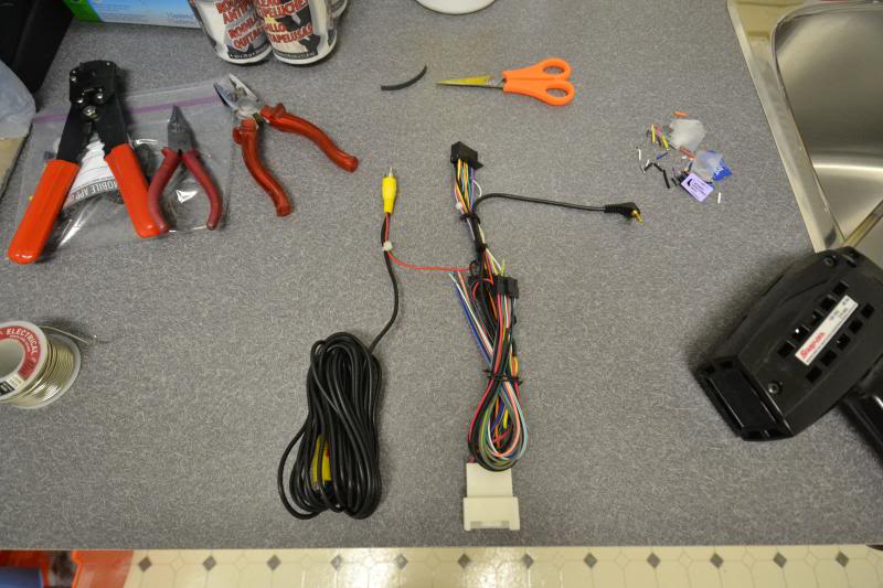
6. Pioneer Headunit Prep
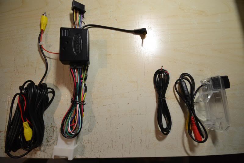
I've always been used to having a double din headunit with a screen in all my vehicles. The buttons on the factory radio wasn't very appealing to me either so I've been collecting various parts for the past month in preparation for the job. The two main items I'm tackling first is the headunit itself and the reverse backup camera.
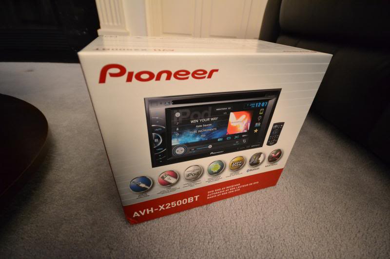
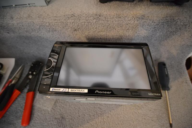
My choice of headunit is the Pioneer AVH-X2500BT. I opted not to go with built-in navigation as I've had poor experience with updating maps and find it much easier to use my phone or pick up a Garmin if need be.
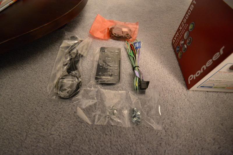
Layout of all the items included with the headunit. The remote I will probably set aside. Pioneer includes a USB cable and I will supply my own 3.5mm aux cable. Both will be relocated to the glove box. I thought about retro-fitting with the factory USB in the center console but that would still leave a 3.5mm aux cable hanging around. As for the mic, I am thinking where the front dome lights are located for a discrete install.
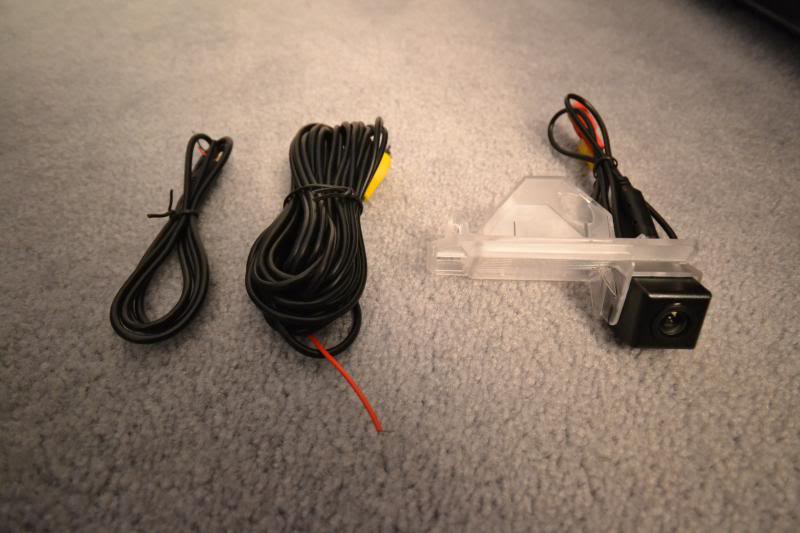
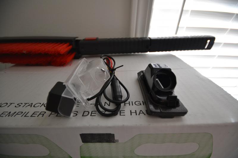
The backup camera I decided to go with. I felt the option for the factory camera was too far offset to the left of the vehicle. This should bring the camera closer to the center of the bumper.
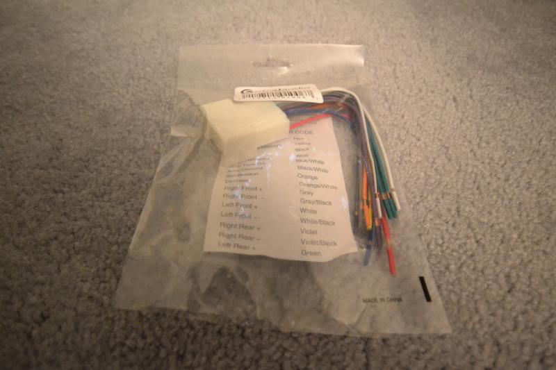
The harness to match with the car harness. I later learned that this harness was not the best as it does not include the wires to retain the factory steering wheel controls if need be. I am unsure if the Metra harness will be better. This harness was included with the dash install kit from Metra, but the harness itself is an off brand.
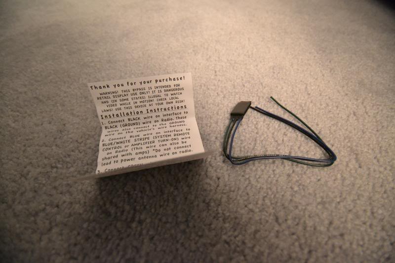
This is the bypass for the parking brake engagement. It is essentially a relay delayed to send a signal from the parking brake as the newer Pioneer units have to see a cut in the signal for the bypass to activate. In the past, it was a simple grounding of the parking brake wire but that is no longer acceptable with the new designs.
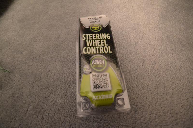
This is one of the many steering wheel controller retention devices available. I heard the best reviews about Axxess but most are compatible. This should also retain the bluetooth controls.
A quick mock up of where all the connections will go. All the colors match up so it is a very straight forward install.
The second pins from the left on both the top and bottom were empty when I received the harness. These are for the steering wheel controls which I ended up sourcing my own pins to install with the Axxess integration.
This diagram shows the harness on the vehicle side. The two pins for the steering wheel control are 22 and 32.
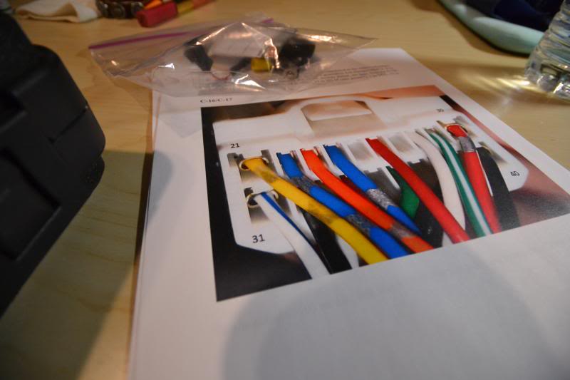
A poor attempt to capture which two wires I am talking about. The blue wire for pin 22 goes to the ASWC-1 and the black wire for pin 32 goes to chassis ground.
More to come later!
My choice of headunit is the Pioneer AVH-X2500BT. I opted not to go with built-in navigation as I've had poor experience with updating maps and find it much easier to use my phone or pick up a Garmin if need be.

Layout of all the items included with the headunit. The remote I will probably set aside. Pioneer includes a USB cable and I will supply my own 3.5mm aux cable. Both will be relocated to the glove box. I thought about retro-fitting with the factory USB in the center console but that would still leave a 3.5mm aux cable hanging around. As for the mic, I am thinking where the front dome lights are located for a discrete install.

The backup camera I decided to go with. I felt the option for the factory camera was too far offset to the left of the vehicle. This should bring the camera closer to the center of the bumper.

The harness to match with the car harness. I later learned that this harness was not the best as it does not include the wires to retain the factory steering wheel controls if need be. I am unsure if the Metra harness will be better. This harness was included with the dash install kit from Metra, but the harness itself is an off brand.

This is the bypass for the parking brake engagement. It is essentially a relay delayed to send a signal from the parking brake as the newer Pioneer units have to see a cut in the signal for the bypass to activate. In the past, it was a simple grounding of the parking brake wire but that is no longer acceptable with the new designs.

This is one of the many steering wheel controller retention devices available. I heard the best reviews about Axxess but most are compatible. This should also retain the bluetooth controls.

A quick mock up of where all the connections will go. All the colors match up so it is a very straight forward install.

The second pins from the left on both the top and bottom were empty when I received the harness. These are for the steering wheel controls which I ended up sourcing my own pins to install with the Axxess integration.

This diagram shows the harness on the vehicle side. The two pins for the steering wheel control are 22 and 32.

A poor attempt to capture which two wires I am talking about. The blue wire for pin 22 goes to the ASWC-1 and the black wire for pin 32 goes to chassis ground.

More to come later!

Thread Starter
Evolving Member
Joined: Sep 2013
Posts: 265
Likes: 1
From: Calgary, AB
7. Radio Wiring Harness
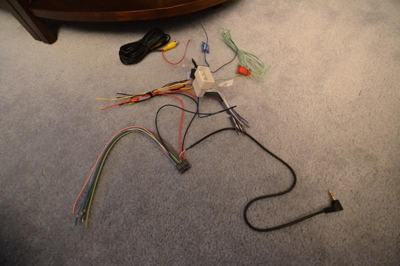
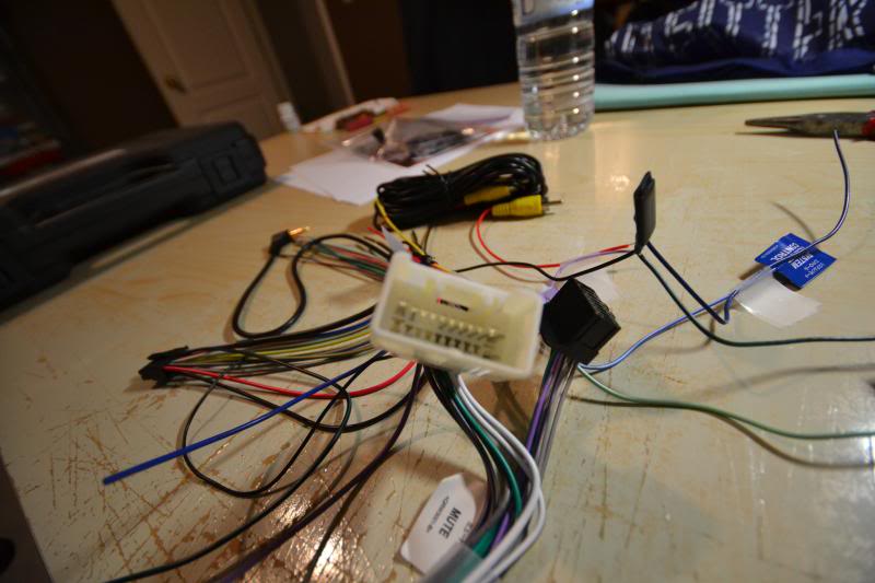
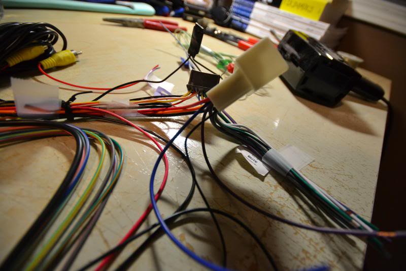
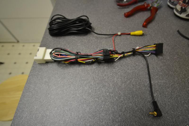
Here are some pictures of the wiring harness for the radio. I just got her all buttoned up last night. This harness includes the factory plug to the Pioneer plug, parking brake bypass, ASWC-1 steering wheel controller, and hardwire for reverse backup camera.
The colors are easy to match up. Just take some time with a little solder and heat shrink to make sure everything has a solid connection. Every install may be different from mine so I won't list all the colors, but if there are certain items you're interested in then please ask and I'd be happy to help with what I can.
The colors are easy to match up. Just take some time with a little solder and heat shrink to make sure everything has a solid connection. Every install may be different from mine so I won't list all the colors, but if there are certain items you're interested in then please ask and I'd be happy to help with what I can.


Thread Starter
Evolving Member
Joined: Sep 2013
Posts: 265
Likes: 1
From: Calgary, AB
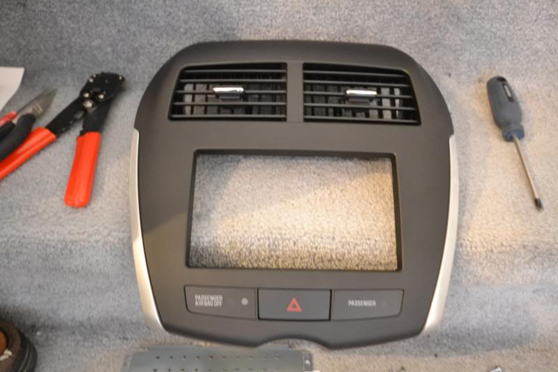
8. Removing the Factory Headunit
I took as many pictures as possible during the whole process of installing the Pioneer headunit and backup camera that I'll need to break down the procedure into multiple posts. To start, lets cover the removal of the stock headunit.
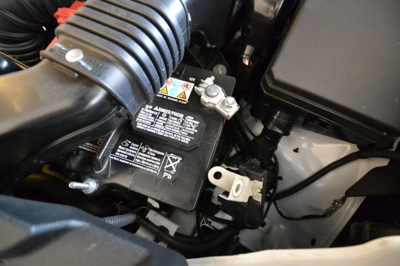
For safety, disconnect the negative terminal to the battery. This is a 12mm socket.
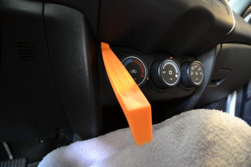
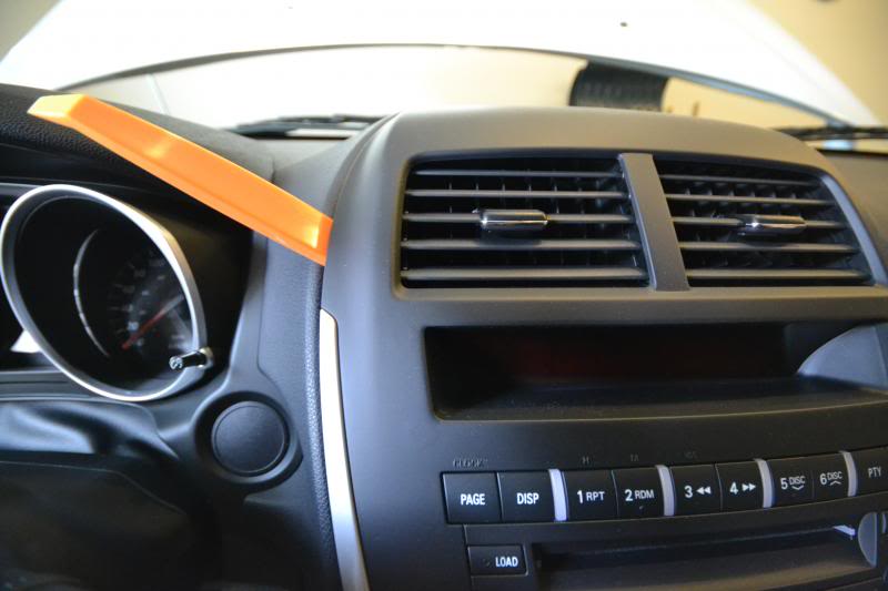
To remove the radio dash cover, start prying on the bottom near the HVAC controls and work your way up around the sides to the top.
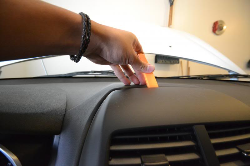
Here is a picture of the radio cover immediately after it comes loose. Disconnect the harness for the hazard switch.
The radio cover separated from the dash.
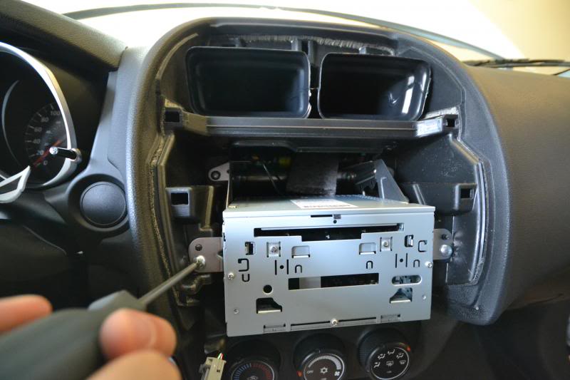
Start removing the 4 Phillips screws on the radio bracket.
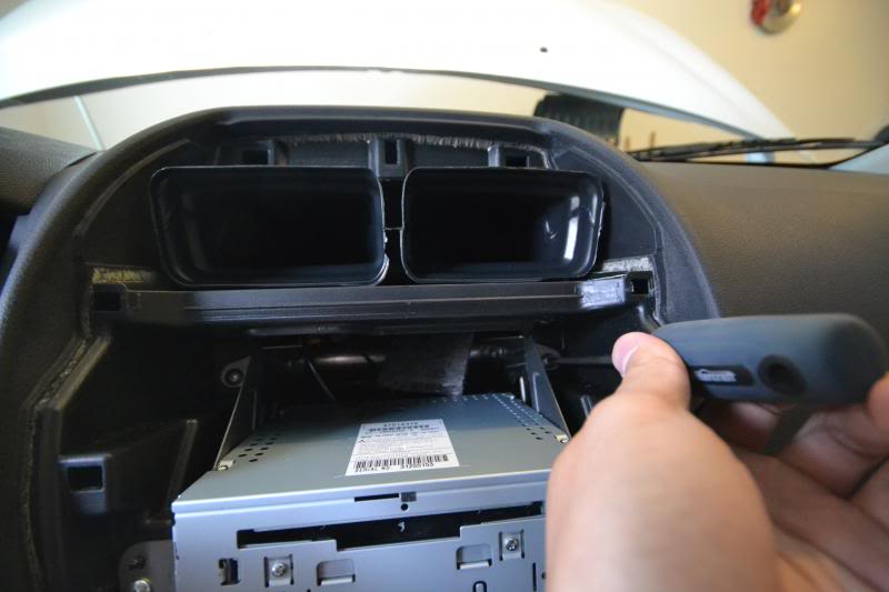
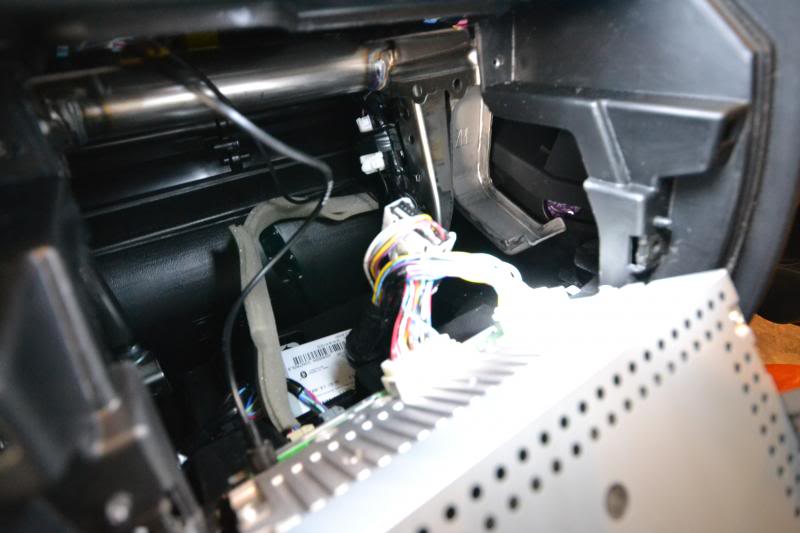
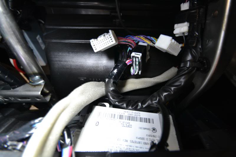
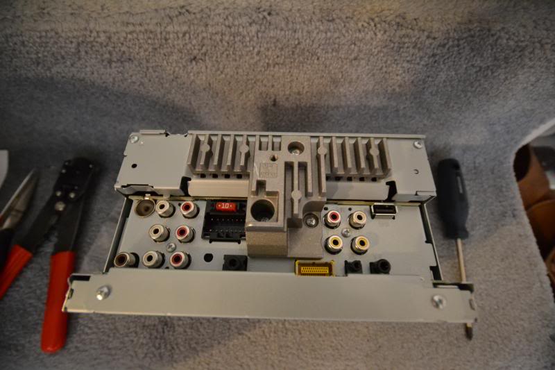
Pull out the headunit and note the 3 connectors attached on the back. Two white plugs and the antenna wire.
This is what the back of the stock headunit looks like.
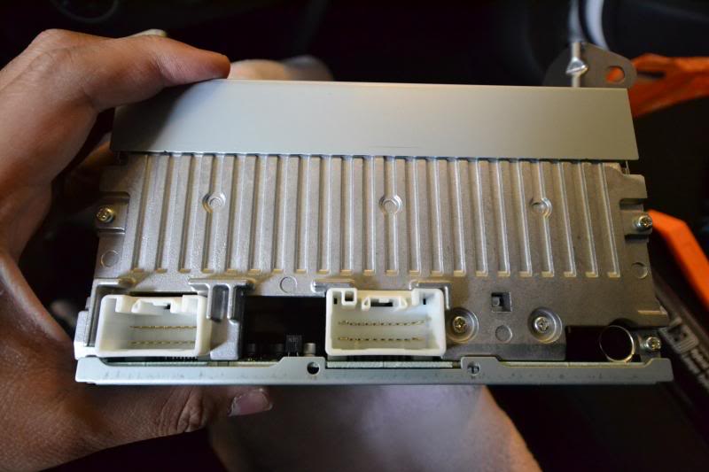
The 20 pin plug is what we're interested in. Set the other 18 pin plug aside. The antenna wire will be used for later so place it in a safe area away from the open for now to avoid damage when test fitting. No adapter is required for the antenna to fit the Pioneer AVH-X2500BT.
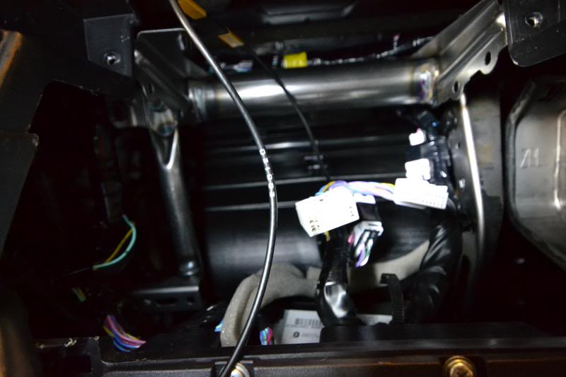
For reference, the bluetooth and sat radio is located below the stock headunit above the HVAC controls. The device is secured in place so I did not bother to remove it in case I ever go back to stock. It is out of the way anyways so not a big deal.
For safety, disconnect the negative terminal to the battery. This is a 12mm socket.

To remove the radio dash cover, start prying on the bottom near the HVAC controls and work your way up around the sides to the top.


Here is a picture of the radio cover immediately after it comes loose. Disconnect the harness for the hazard switch.

The radio cover separated from the dash.

Start removing the 4 Phillips screws on the radio bracket.


Pull out the headunit and note the 3 connectors attached on the back. Two white plugs and the antenna wire.

This is what the back of the stock headunit looks like.

The 20 pin plug is what we're interested in. Set the other 18 pin plug aside. The antenna wire will be used for later so place it in a safe area away from the open for now to avoid damage when test fitting. No adapter is required for the antenna to fit the Pioneer AVH-X2500BT.

For reference, the bluetooth and sat radio is located below the stock headunit above the HVAC controls. The device is secured in place so I did not bother to remove it in case I ever go back to stock. It is out of the way anyways so not a big deal.

Last edited by infected; Nov 9, 2013 at 04:38 PM. Reason: Screws/bolts details added.

Thread Starter
Evolving Member
Joined: Sep 2013
Posts: 265
Likes: 1
From: Calgary, AB
Unfortunately, no. What you could do is retro-fit with the new USB but I personally haven't justified the need to have the cables hidden in the arm rest. The next couple posts will show my 3.5mm and USB tucked into the glove box. I think I'll try it out for now but if you ever attempt the retro-fit when you do your install, then please keep me posted!
Thread Starter
Evolving Member
Joined: Sep 2013
Posts: 265
Likes: 1
From: Calgary, AB
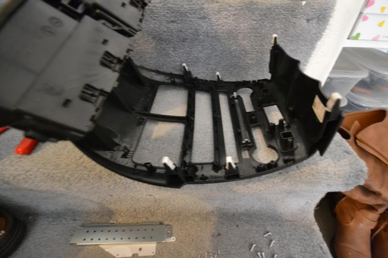
9. Disassembly of the Stock Radio Panel
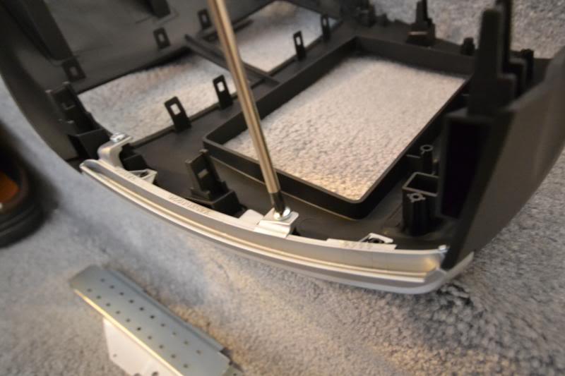
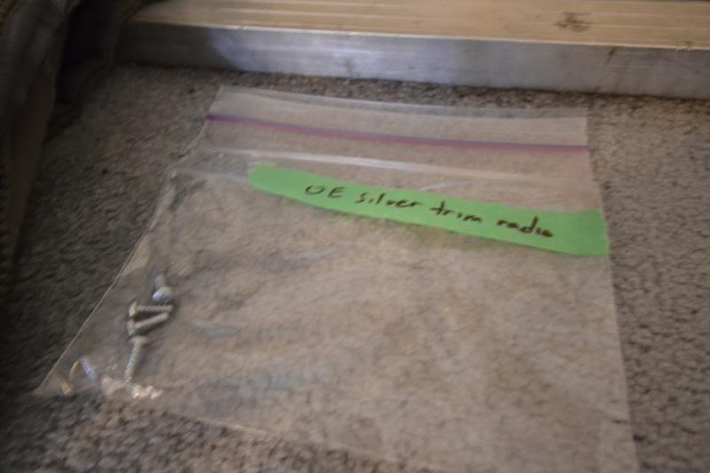
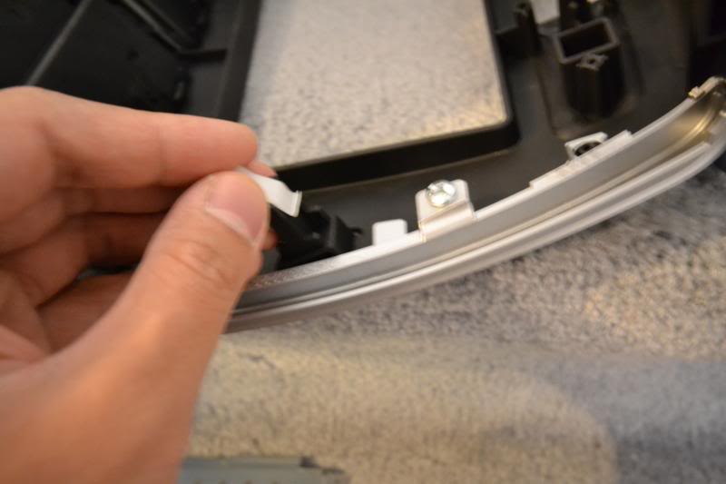
Remove the 4 Phillips screws attaching the two silver trims on the edges of the radio panel. These will be re-used for later.
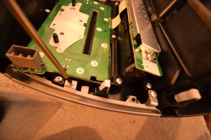
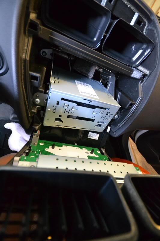
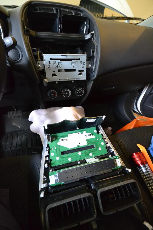
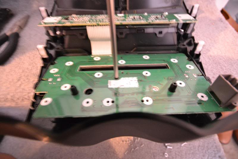
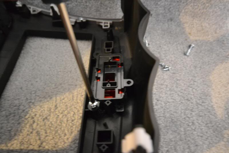
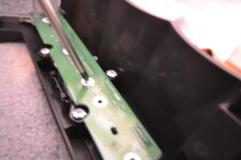
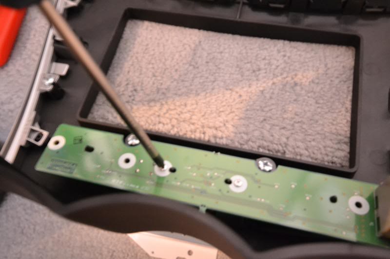
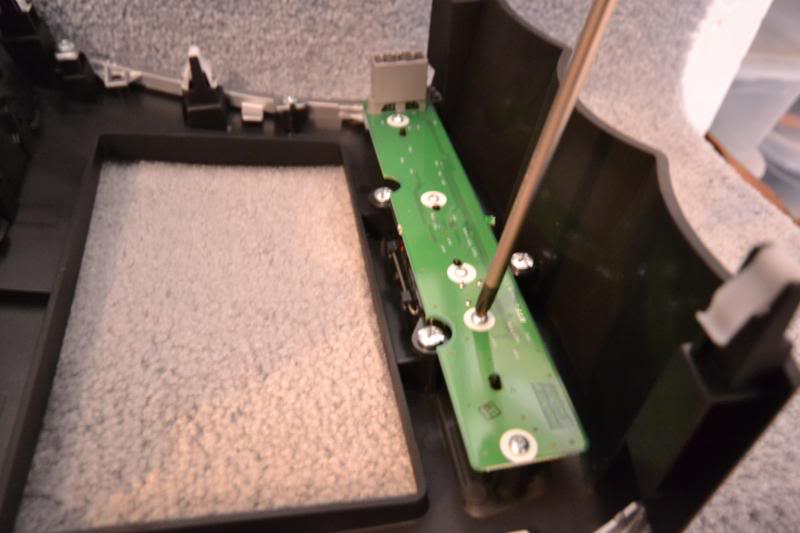
Remove 16 of the small Phillips screws on the green circuit board. We will be re-using 2 of the small screws for later.
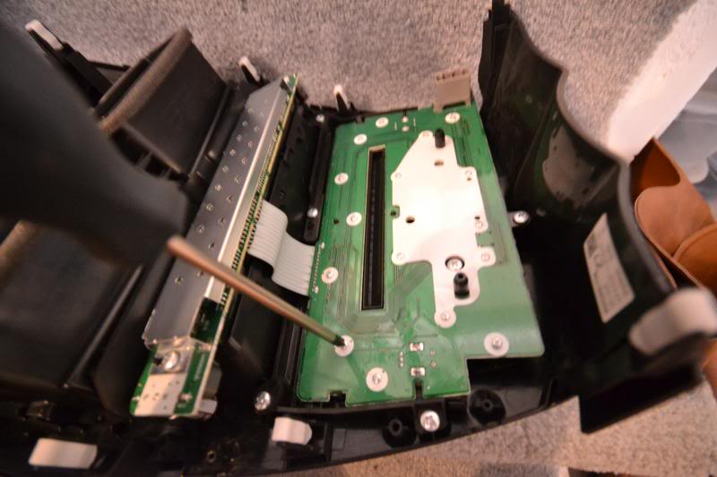
Now remove 11 of the larger Phillips screws on the outer edge of the panel.
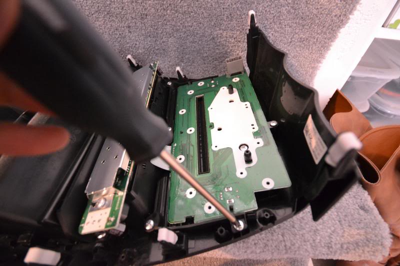
Of the 11, this also includes three which go through the panel. They are rather discrete so be sure not to miss them. When all the screws are out, the circuit board should free itself easily without much force required at all.
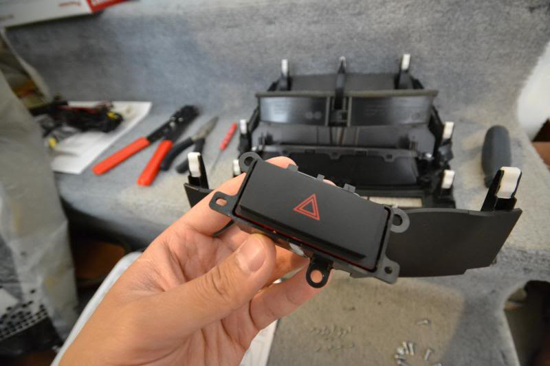
The hazard switch may now be removed. Save this to be re-used for the new radio panel.
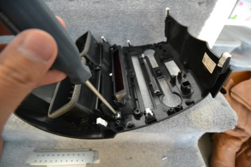
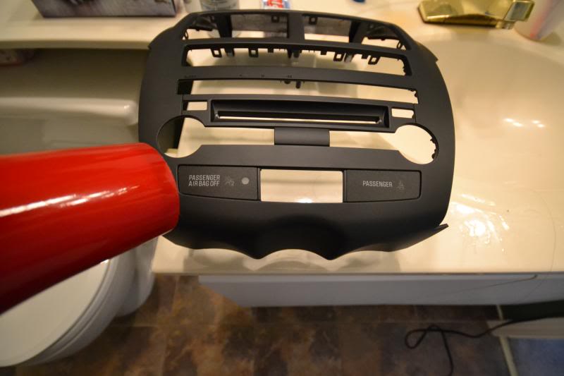
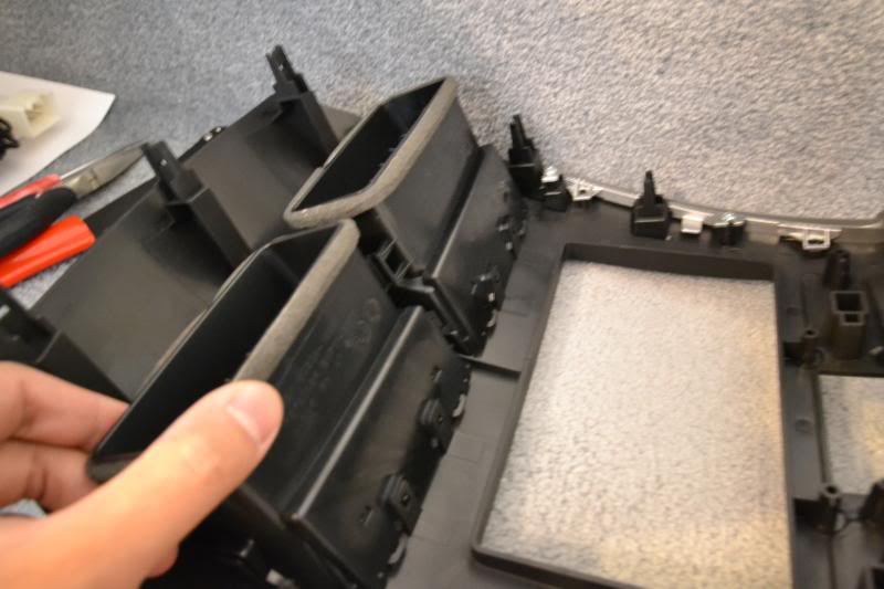
Remove the final 3 Phillips screws directly below the vent. Then unclip the vent from the radio panel.
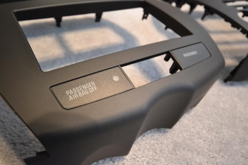
The two seatbelt and airbag labels will need to be removed and re-used on the new panel. Apply some heat to the labels and gently lift them away. Be careful not to bend or scratch the labels.

Remove 16 of the small Phillips screws on the green circuit board. We will be re-using 2 of the small screws for later.

Now remove 11 of the larger Phillips screws on the outer edge of the panel.

Of the 11, this also includes three which go through the panel. They are rather discrete so be sure not to miss them. When all the screws are out, the circuit board should free itself easily without much force required at all.

The hazard switch may now be removed. Save this to be re-used for the new radio panel.

Remove the final 3 Phillips screws directly below the vent. Then unclip the vent from the radio panel.


The two seatbelt and airbag labels will need to be removed and re-used on the new panel. Apply some heat to the labels and gently lift them away. Be careful not to bend or scratch the labels.


Last edited by infected; Nov 9, 2013 at 11:07 PM. Reason: Added more detail.
Thread Starter
Evolving Member
Joined: Sep 2013
Posts: 265
Likes: 1
From: Calgary, AB
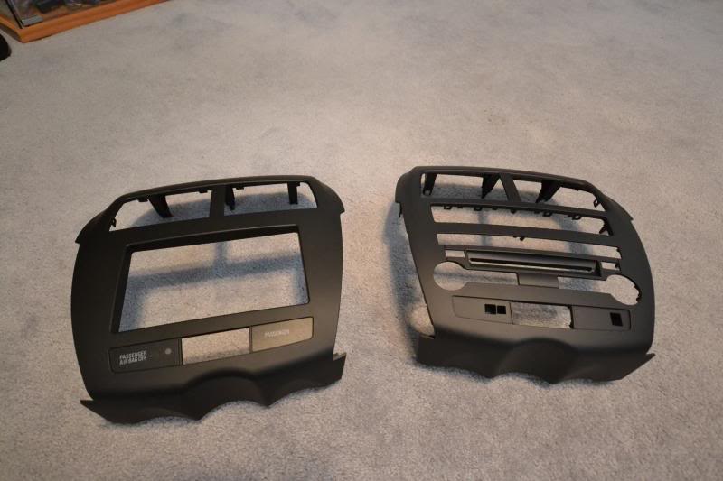
10. Metra Radio Panel Assembly
The Metra dash kit I used is for all models of the Outlander Sport/ASX/RVR. Part number 99-70148.
Re-use the silver trims we removed earlier. Metra supplies 4 new Phillips screws for the trim. Save the old hardware and label because it'll be hard to remember a couple years down the road if you ever want to revert back to stock.
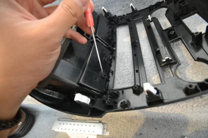
Re-attach the vent. It should just clip in to place. Start with aligning the top clips first and then the bottom clips last.
Install the supplied 9 panel clips by simply pushing into the pegs.
Re-attach the hazard switch with the supplied 3 Phillips screws.
Align the new circuit board and use the 2 small Phillips we saved earlier for the middle of the panel.
Use the supplied 3 Phillips to secure the outside edges of the same circuit panel.
Final inspection to make sure everything is installed tight and no scratches on the surface.
Re-use the silver trims we removed earlier. Metra supplies 4 new Phillips screws for the trim. Save the old hardware and label because it'll be hard to remember a couple years down the road if you ever want to revert back to stock.


Re-attach the vent. It should just clip in to place. Start with aligning the top clips first and then the bottom clips last.

Install the supplied 9 panel clips by simply pushing into the pegs.

Re-attach the hazard switch with the supplied 3 Phillips screws.

Align the new circuit board and use the 2 small Phillips we saved earlier for the middle of the panel.


Use the supplied 3 Phillips to secure the outside edges of the same circuit panel.

Final inspection to make sure everything is installed tight and no scratches on the surface.

Thread Starter
Evolving Member
Joined: Sep 2013
Posts: 265
Likes: 1
From: Calgary, AB
11. Pioneer AVH-X2500BT Install
Here is the star of the show.
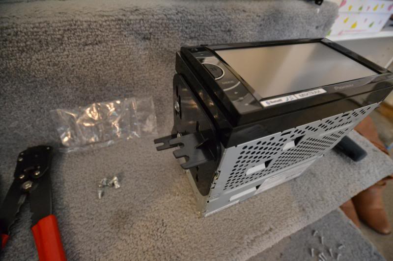
Attach the brackets to the headunit with 3 of the supplied Phillips screws on each side that came with the headunit.
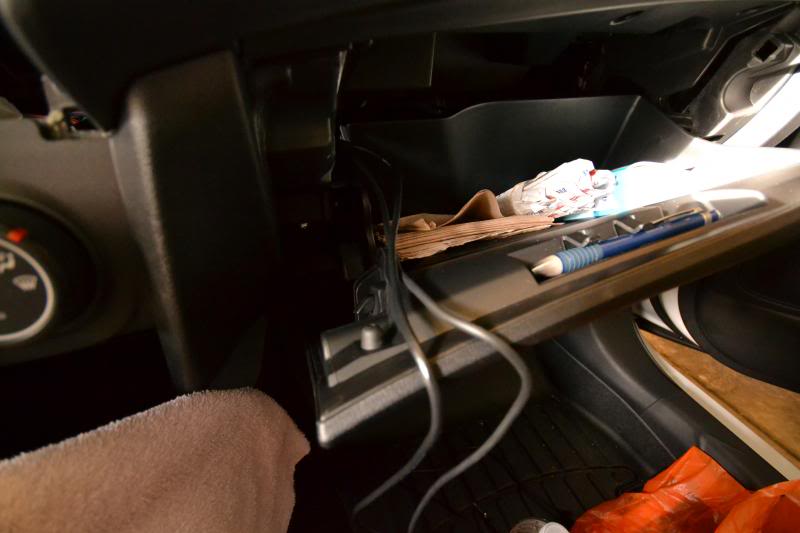
This is a look to the right near the glove box. I routed the 3.5mm and USB cable through here.
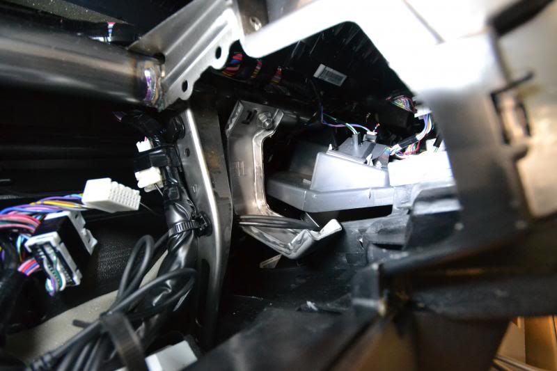
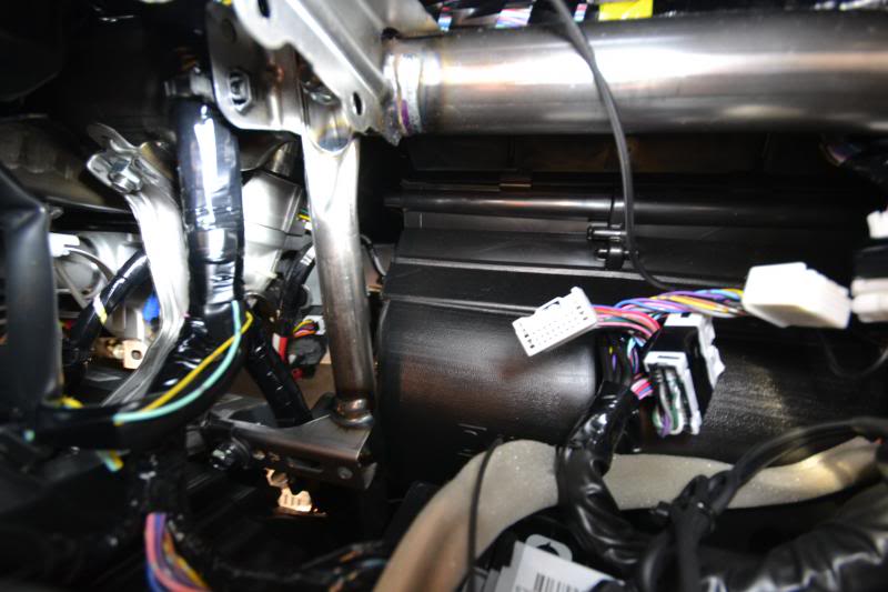
This is a look to the left near the steering column where I routed the mic and hardwire for the reverse backup camera cable.
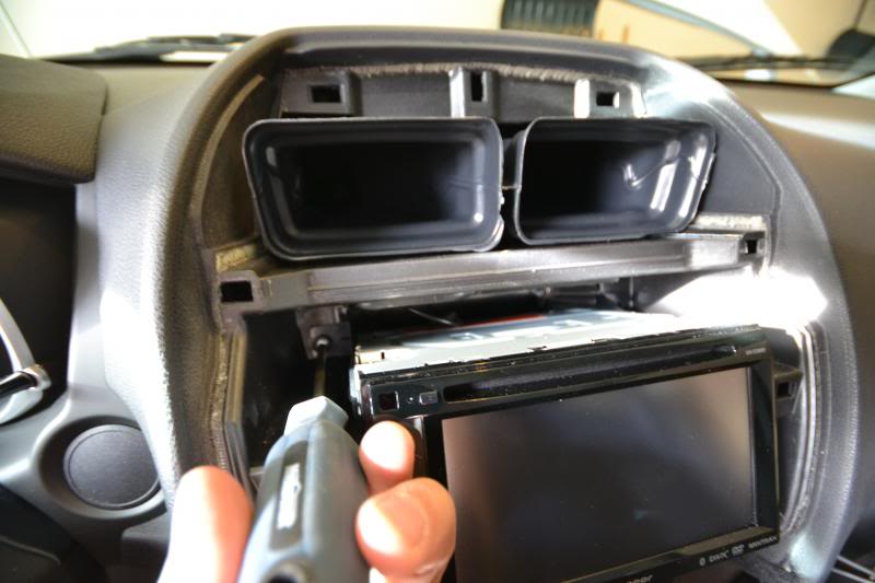
Make all the connections and carefully slide the headunit into place.
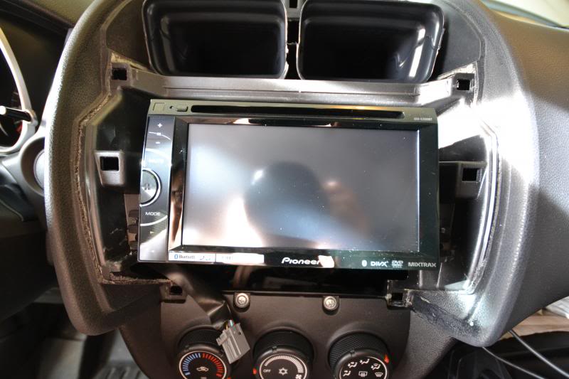
Secure the brackets with the original 4 Phillips screws.
Reconnect the hazard switch and gently prop the radio panel into place. Re-connect the negative battery terminal and test out all of the connections for power, steering wheel control, bluetooth, etc.
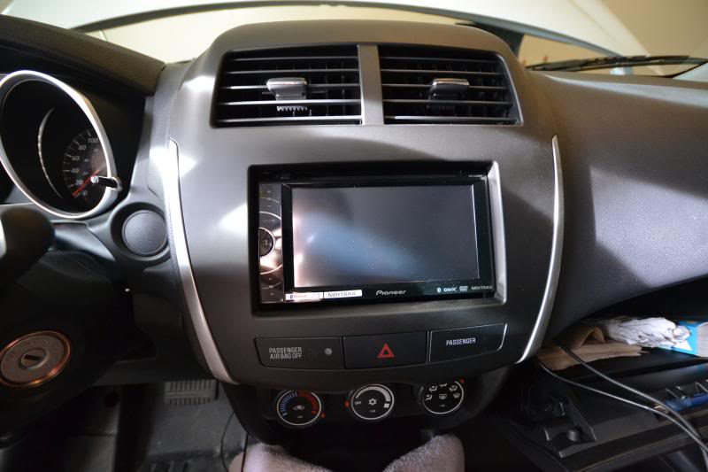
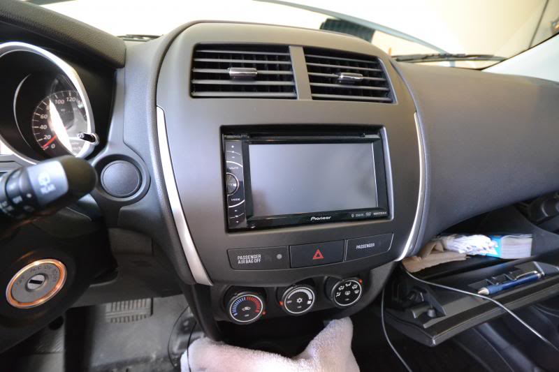
Secure the radio panel in place once everything checks out ok and do a second inspection for gaps/fitment.
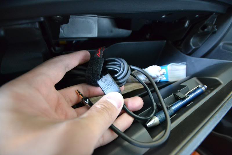
Here is the 3.5mm and USB bundle I relocated to the glove box. The stock USB in the arm rest will no longer function. It would be an easy job to retro-fit the USB but I have no need for that at the moment. Will see how much I like the cable in the glove box versus the arm rest for now.


Attach the brackets to the headunit with 3 of the supplied Phillips screws on each side that came with the headunit.

This is a look to the right near the glove box. I routed the 3.5mm and USB cable through here.


This is a look to the left near the steering column where I routed the mic and hardwire for the reverse backup camera cable.

Make all the connections and carefully slide the headunit into place.

Secure the brackets with the original 4 Phillips screws.

Reconnect the hazard switch and gently prop the radio panel into place. Re-connect the negative battery terminal and test out all of the connections for power, steering wheel control, bluetooth, etc.

Secure the radio panel in place once everything checks out ok and do a second inspection for gaps/fitment.

Here is the 3.5mm and USB bundle I relocated to the glove box. The stock USB in the arm rest will no longer function. It would be an easy job to retro-fit the USB but I have no need for that at the moment. Will see how much I like the cable in the glove box versus the arm rest for now.

Thread Starter
Evolving Member
Joined: Sep 2013
Posts: 265
Likes: 1
From: Calgary, AB
12. Wiring a Mic and Reverse Backup Camera
To supplement the install of the new headunit, a discrete yet functional mounting location is required for the mic, as goes to a clean install for the backup camera. I ran both wires under the dash below the steering column along the outside edges of the exterior panel. Take a peek and you will see a ridge along the plastic for the wires to stay in place. Then exit along the three way meet of the side toe kick panel, side trim, and lower dash trim.
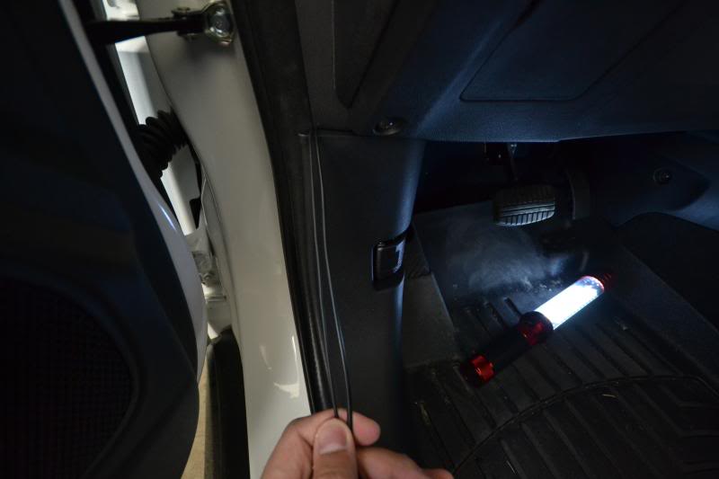
Begin to route the wires up along the door seal and tuck then nicely behind with a gentle push after to keep everything firmly in place.
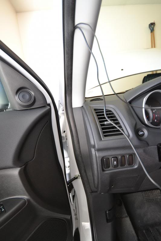
Continue to route the mic wire towards the front of the vehicle along the A-pillar trim.
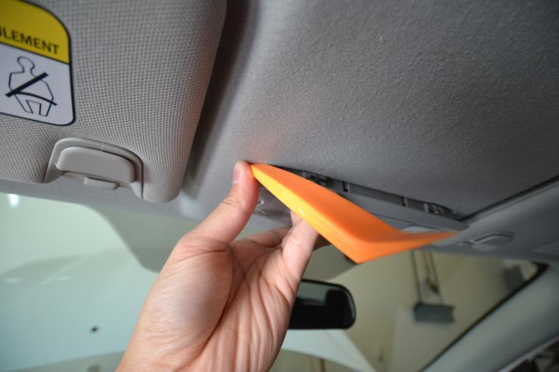
Pry along the front overhead dome light on the side facing the rear of the vehicle. There are two metal tabs which will release easily. Unplug the two cables attached.
There is a mouse hole in the headliner directly above the rearview mirror. Run the mic through the hole and the rest of the wire will follow easily. Give it a gentle tug to make sure the rest of the wire along the top of the windshield and between the headliner is pulled in and away from the edge.
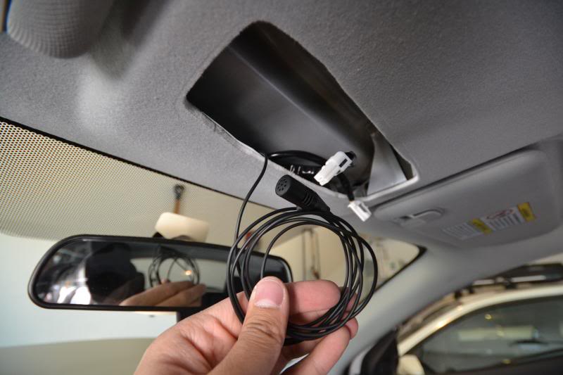
Tuck the mic in the middle opening of the dome light switch. Secure with double-side tape and aim the mic towards the mesh opening.
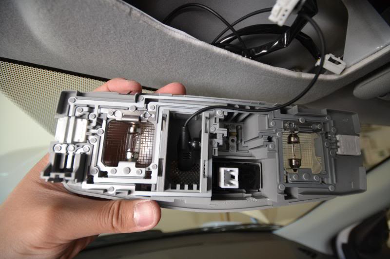
Remember to re-attach the two plugs that were disconnected earlier and pop everything back into place.
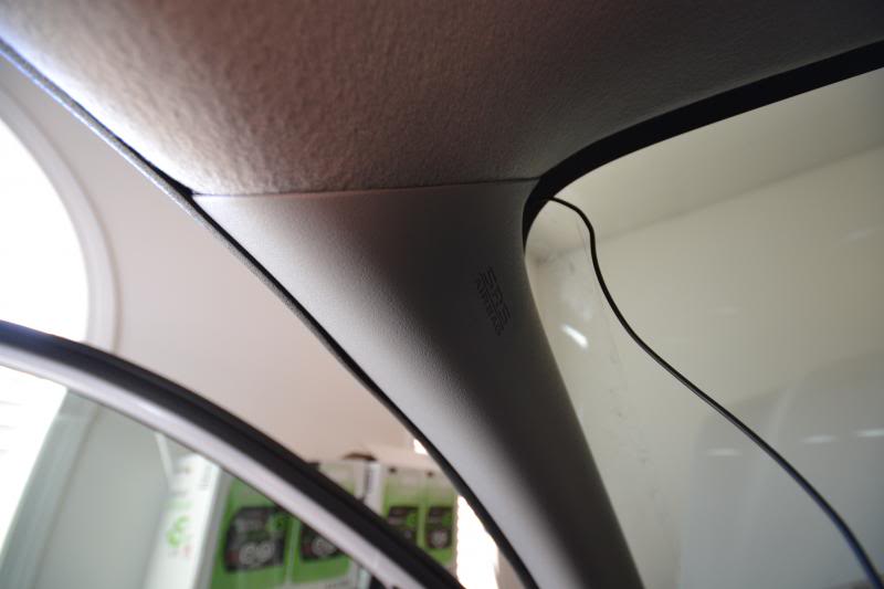
Moving along with the backup camera wire, route it the other direction away from the mic wire after the junction at the top of the A-pillar where we left of earlier. Run it along the inside between the headliner to the B-pillar and C-pillar.
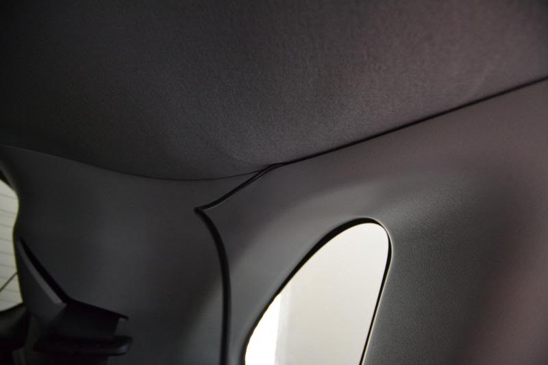
Remove the upper panel first. It is a three piece and held together with clips only. I found it easier to start at either end and work towards the other end when removing. It will come off as one big piece this way.
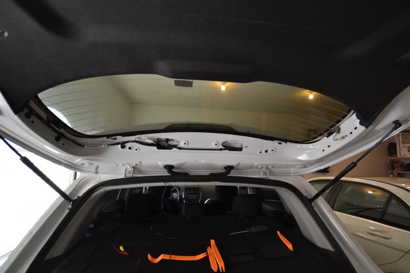
Two black push-pins will be revealed on the larger panel on each end. Remove and then pry away the panel. Again, it should now only be held in with clips.
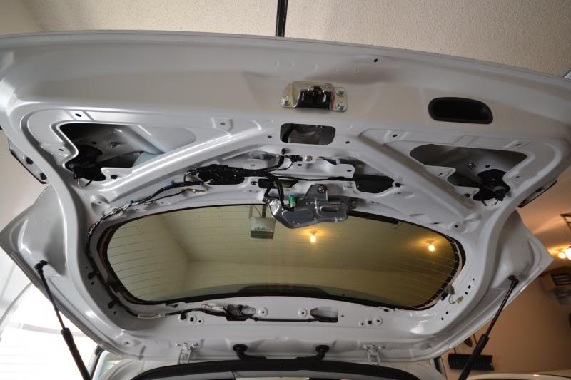
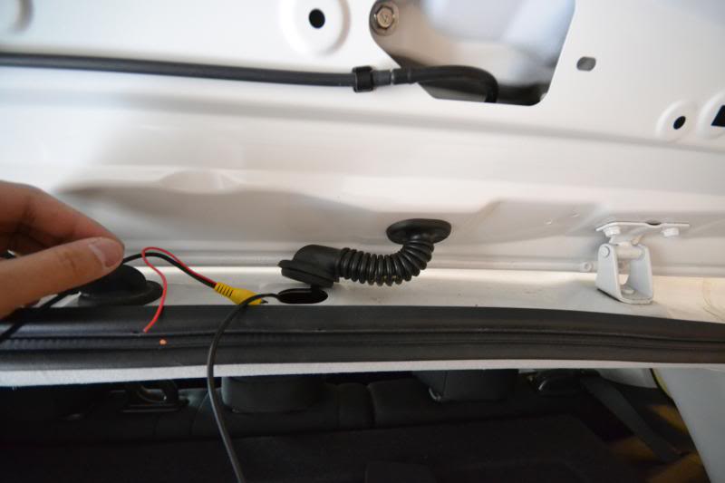
Choose which of the rubber grommets you would like to run your wiring. The left is all electrical and the right is for the washer fluid hose. I decided to run it on the right to isolate from the other electrical lines in case of interference with the video. Either grommet will work though. The fit is snug so use some elbow grease to get the lead started and work its way through. There are three pins holding the headliner in which I also removed to make easier access for running the wiring through the grommet.
Slide the driver side license plate light housing to the left of the vehicle and it will release.
Side by side profile of the old license plate light housing with the new housing and build in camera.
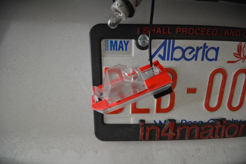
The new housing has no reflective material on the inside to help re-direct some of the light. I did a test fit and found the new housing works just as well compared to the second housing still on the car, so I decided against any further work with the reflective material. The light socket is not the best fit. It is snug and will stop water leaks but there is no end point on the housing, meaning the socket can turn and turn. Give it a 90 degree twist and leave it as is before inserting back into the opening to make sure the socket and housing has the most secure fit.
I noticed the old housing had a rubber seal along the edge where as the new housing does not. When installed, it was loose and had a lot of movement/openings. I used some thick double-side tape cut to shape along the entire perimeter of the new housing to act as a new seal between the housing and the car body. The feel should be a nice snug and secure fit when you push the assembly in. This will prevent any water leaks especially if you are in a rain or snow climate.
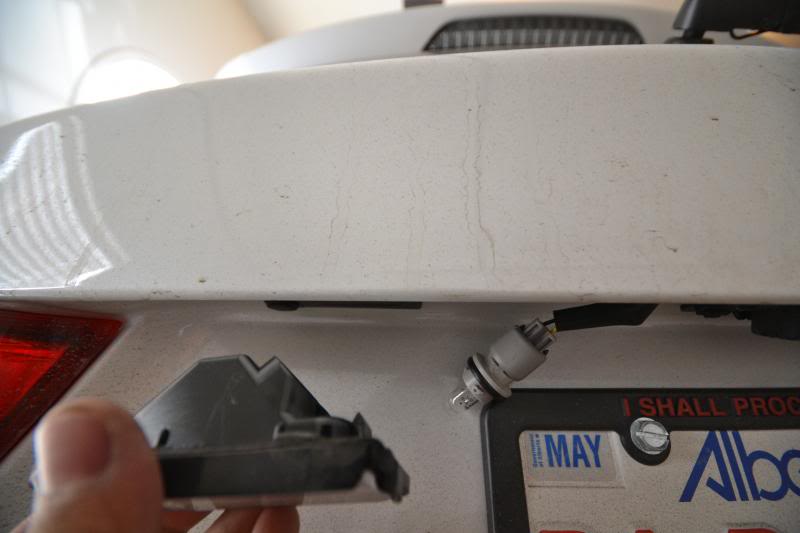
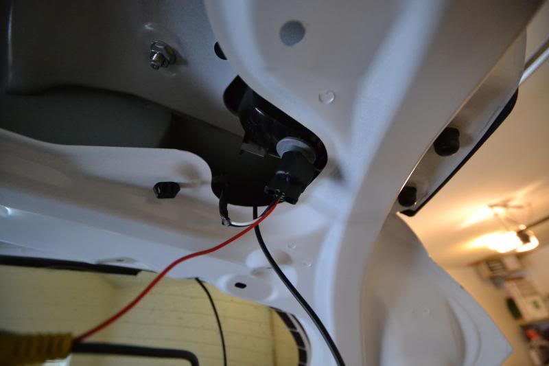
To draw power for the camera, locate the rear wiper motor switch.
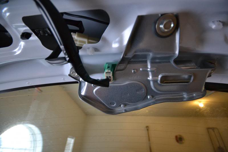
Note the purple wire for power and the black wire left of it for ground.
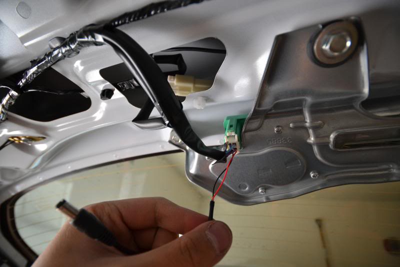
To send a signal to the headunit of a change in current when in reverse, tap the reverse light socket on either the left or right side depending on which grommet you ran your wires through earlier. The wire you want is the white one.
Make all your connections and tidy up the wiring for a clean install. Make sure you clear any of the holes needed for re-attaching the clips for the panels later from catching or damaging any of the new wiring.

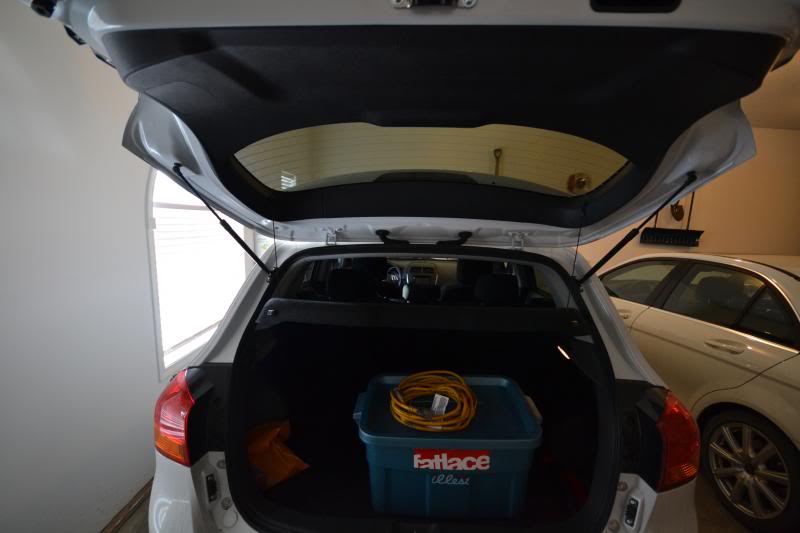
The panels go back in reverse order. Start with the big panel. The triple panel on the top may now be separated to install the sides first, and finally the center panel last. There should be great glory popping that last panel in place as all the hard work is near complete with a nice and clean install, as if no one was ever even here!
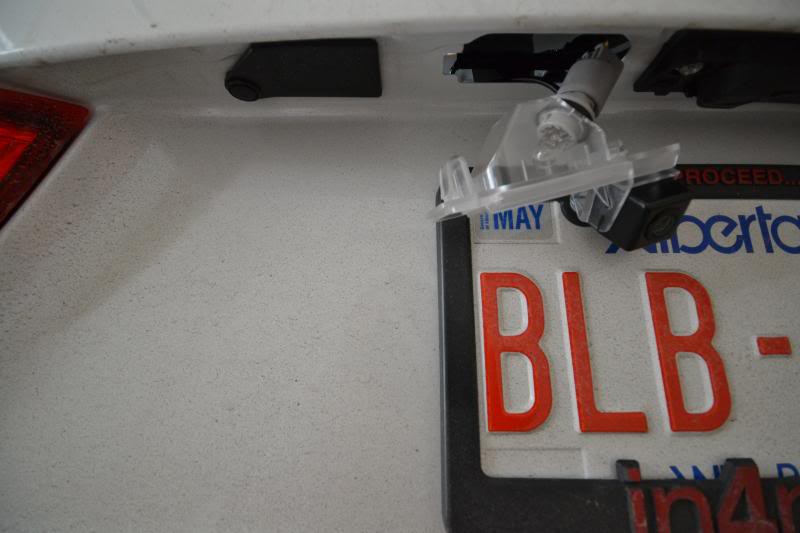
Outside view of the new housing with built in camera.
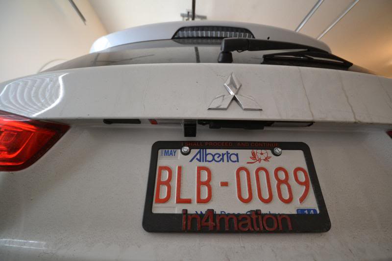
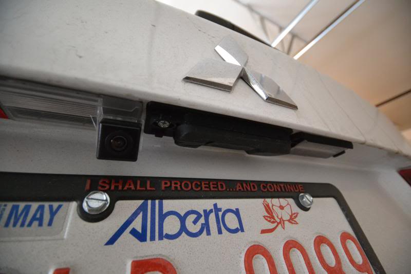
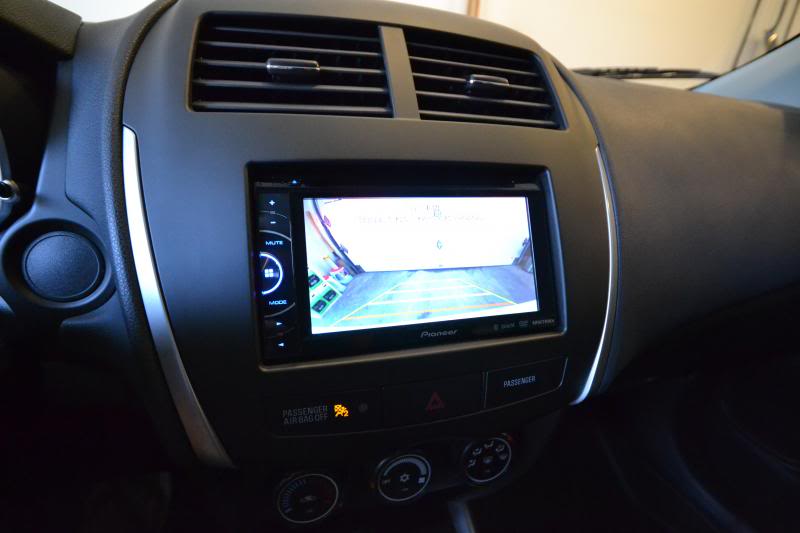
Cheers to a job well done! On the Pioneer, I set the camera to 'power' polarity for the screen to automatically switch over to reverse camera view when the transmission is in reverse. The camera is relatively center and just grabs a portion of the bumper so I can tell exactly where we are with spacing.
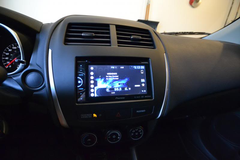
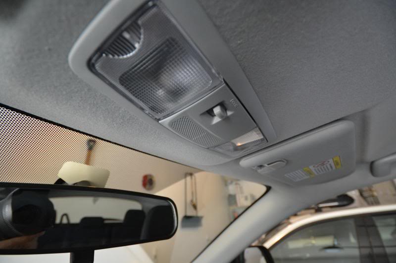
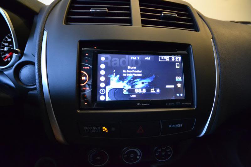
I really like the color match of the lighting to the factory switches. The new color selection for the Pioneer units has improved substantially compared to the past. Now time to sit back and enjoy! I also really enjoy how much the new headunit cleaned up the cluster of buttons and switches compared to when the stock radio was still in. I hope this was helpful to anyone interested in doing this as a DIY. Please use this guide for reference only, and refrain from distracted driving with video in motion while driving. I'm sure you all know better though!

Begin to route the wires up along the door seal and tuck then nicely behind with a gentle push after to keep everything firmly in place.

Continue to route the mic wire towards the front of the vehicle along the A-pillar trim.

Pry along the front overhead dome light on the side facing the rear of the vehicle. There are two metal tabs which will release easily. Unplug the two cables attached.

There is a mouse hole in the headliner directly above the rearview mirror. Run the mic through the hole and the rest of the wire will follow easily. Give it a gentle tug to make sure the rest of the wire along the top of the windshield and between the headliner is pulled in and away from the edge.

Tuck the mic in the middle opening of the dome light switch. Secure with double-side tape and aim the mic towards the mesh opening.

Remember to re-attach the two plugs that were disconnected earlier and pop everything back into place.

Moving along with the backup camera wire, route it the other direction away from the mic wire after the junction at the top of the A-pillar where we left of earlier. Run it along the inside between the headliner to the B-pillar and C-pillar.

Remove the upper panel first. It is a three piece and held together with clips only. I found it easier to start at either end and work towards the other end when removing. It will come off as one big piece this way.

Two black push-pins will be revealed on the larger panel on each end. Remove and then pry away the panel. Again, it should now only be held in with clips.

Choose which of the rubber grommets you would like to run your wiring. The left is all electrical and the right is for the washer fluid hose. I decided to run it on the right to isolate from the other electrical lines in case of interference with the video. Either grommet will work though. The fit is snug so use some elbow grease to get the lead started and work its way through. There are three pins holding the headliner in which I also removed to make easier access for running the wiring through the grommet.

Slide the driver side license plate light housing to the left of the vehicle and it will release.

Side by side profile of the old license plate light housing with the new housing and build in camera.

The new housing has no reflective material on the inside to help re-direct some of the light. I did a test fit and found the new housing works just as well compared to the second housing still on the car, so I decided against any further work with the reflective material. The light socket is not the best fit. It is snug and will stop water leaks but there is no end point on the housing, meaning the socket can turn and turn. Give it a 90 degree twist and leave it as is before inserting back into the opening to make sure the socket and housing has the most secure fit.

I noticed the old housing had a rubber seal along the edge where as the new housing does not. When installed, it was loose and had a lot of movement/openings. I used some thick double-side tape cut to shape along the entire perimeter of the new housing to act as a new seal between the housing and the car body. The feel should be a nice snug and secure fit when you push the assembly in. This will prevent any water leaks especially if you are in a rain or snow climate.

To draw power for the camera, locate the rear wiper motor switch.

Note the purple wire for power and the black wire left of it for ground.

To send a signal to the headunit of a change in current when in reverse, tap the reverse light socket on either the left or right side depending on which grommet you ran your wires through earlier. The wire you want is the white one.

Make all your connections and tidy up the wiring for a clean install. Make sure you clear any of the holes needed for re-attaching the clips for the panels later from catching or damaging any of the new wiring.

The panels go back in reverse order. Start with the big panel. The triple panel on the top may now be separated to install the sides first, and finally the center panel last. There should be great glory popping that last panel in place as all the hard work is near complete with a nice and clean install, as if no one was ever even here!

Outside view of the new housing with built in camera.


Cheers to a job well done! On the Pioneer, I set the camera to 'power' polarity for the screen to automatically switch over to reverse camera view when the transmission is in reverse. The camera is relatively center and just grabs a portion of the bumper so I can tell exactly where we are with spacing.


I really like the color match of the lighting to the factory switches. The new color selection for the Pioneer units has improved substantially compared to the past. Now time to sit back and enjoy! I also really enjoy how much the new headunit cleaned up the cluster of buttons and switches compared to when the stock radio was still in. I hope this was helpful to anyone interested in doing this as a DIY. Please use this guide for reference only, and refrain from distracted driving with video in motion while driving. I'm sure you all know better though!

Last edited by infected; Nov 10, 2013 at 08:36 AM. Reason: Added Details
Thread Starter
Evolving Member
Joined: Sep 2013
Posts: 265
Likes: 1
From: Calgary, AB
13. Flashlight
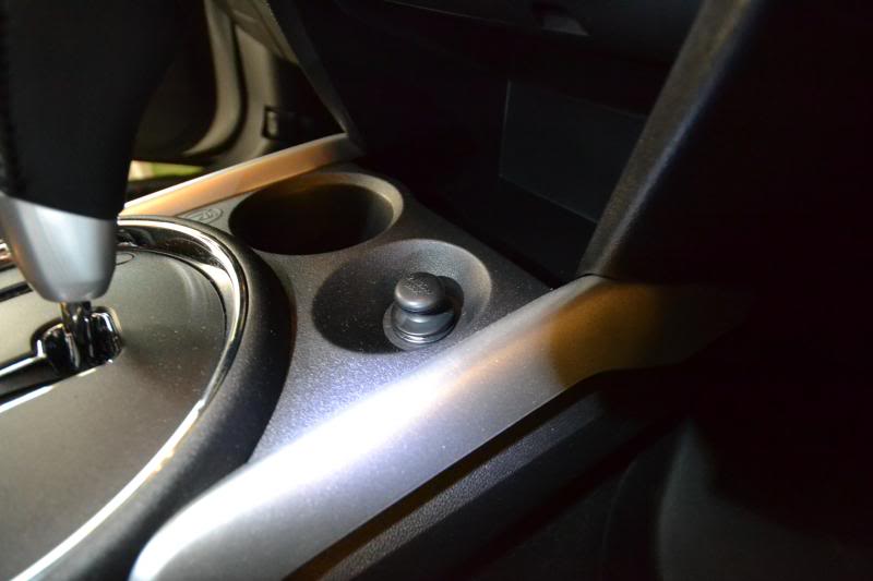
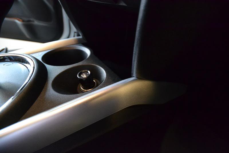
I noticed the RVR isn't the most well equipped with emergency supplies from the factory like I've been used to with other manufacturers. For one thing, visibility is nice when you need it most and I realized the cigarette lighter socket in the center console wasn't serving much purpose; especially with the dummy plug. I don't like wiring anything for power from this socket as seeing cables and wires KILL me. That's why we have the power port in the arm rest.
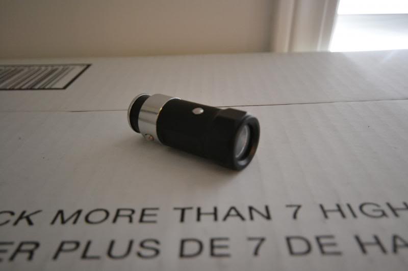
I picked up a rechargeable flashlight from eBay for a couple dollars that fits the cigarette socket. They have black, silver, or blue. I opted for black for a cleaner look.
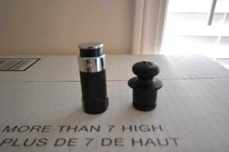
A little fuzzy side profile of the flashlight compared to the dummy plug.
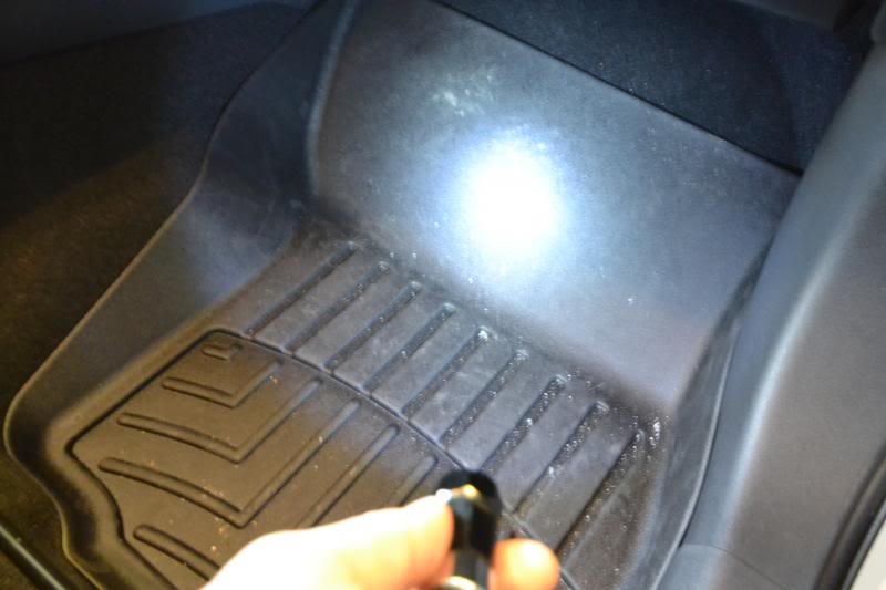
There is a relatively bright SMD which has three operating modes. On, fast SOS, and slow SOS. It's not bad for when it's pitch black outside and some light would be really nice to have.
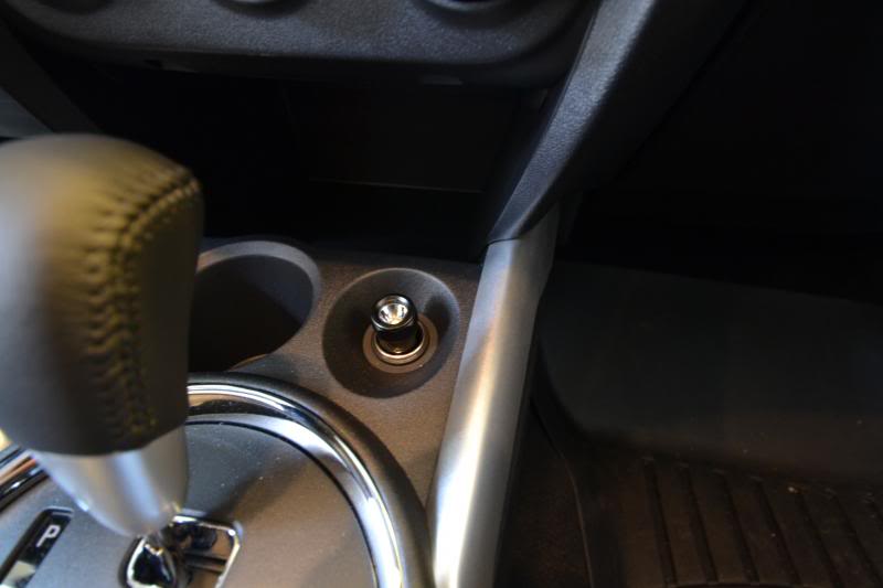
It just pops into place and is as simple as that. No wires or anything to cluster up the look of the interior. Trust me, after having a flashlight offered from BMW in the past, this will really be helpful when the situation calls for it.


Last edited by infected; Nov 10, 2013 at 08:52 AM. Reason: Pictures