When you click on links to various merchants on this site and make a purchase, this can result in this site earning a commission. Affiliate programs and affiliations include, but are not limited to, the eBay Partner Network.
I don't know that answer, but I imagine VERY quickly since the fuel is virtually in-compressible. I will get back to you on that one, if I can determine it.
I have found lots of threads about earlier (pre- X) Evo voltage circuit tapping for bigger pump or surge pump tank control. Not so much for the Evo X. In 2014 it seems CBRD dabbled in some product to handle this problem and then dropped it for reasons I don't know. Some guys spend coin on progressive controllers, I was leaning towards the pressure switch method as described above. The pressure switch SHOULD work, but it feels a bit ghetto. It would be better and cleaner for the ECU to control it. I think this isn't hard to do, and if someone has done this please speak up. It appears that if I CUT the wire connected to fuel pump relay #1 (leg #1 which is coil side on relay) and insert a solid state relay (control side) that I can then replace the pressure switch in my circuit above. The ECU would then control my external DW350il pump for 9v to 13.5v switch.
It should work. Will you still keep the OEM voltage control for in tank pump? I did some tests in this area some time ago, IIRC the relay in engine fuse box is "triggered" by a ground signal, but I may be wrong.
I have a new circuit design that uses three solid state relays and a single diode. No moving parts. No additional relays to fail. The mean time before failure for the crydom relay is 1,317 years. That seems nuts, but its in the datasheet. The new design is:
1.) one wire from front of car to back (ecu signal wire for high voltage to pump)
2.) if tank pump is OFF then surge tank pump is OFF. This is a hard rule. That way if the ECU decides to cut fuel pump power for some reason (like a crash), the surge pump copies it.
3.) If tank pump is on @9v then surge tank is on @9v
4.) If tank pump is on and ECU asks to go to high voltage (based on table in ecu), the surge tank copies the in-tank pump. Optionally the in-tank pump fuse can be pulled to stick it at 9v (to prevent heating in-tank fuel). The surge tank pump listens to the ECU even if in-tank pump is held at 9v.
Cost: under 100 bucks including 12awg silicone high temp wire and 25amp inline fuse.
It should work. Will you still keep the OEM voltage control for in tank pump? I did some tests in this area some time ago, IIRC the relay in engine fuse box is "triggered" by a ground signal, but I may be wrong.
I think that I will keep the voltage control for the in-tank pump, but raise the load value to something much higher. If the relay is a pull to ground, that not a problem - I can flip it to +12v. I just made a tune to test the pump relay in my garage without the car moving. I need to check A-27x pin #1 and pin#2 to see what happens when ECU calls for high voltage. Then I will know if I need to invert it. Either way it will be only one wire I need to run from the front engine compartment to the trunk.
Sure looks like pin#2 (not #1) on relay#1 will do the trick for the single signal wire I need to run to the rear of the car. I will verify 100% tomorrow.
So if relay #1 dies, the ecu is unable to bypass the resistor pack thus holding the in tank pump at 9v and causing a lean condition under boost. I don't need to explain that one further!
I'd say you would need to use relay pin #1 as signal. Pin #2 will be always 12v when engine is on and pin #1 will only be grounded when ECU wants. Pin #1 connects to ECU pin #51. But I might be wrong, I'm sure you will figure it out quickly.
100% Confirmed: PIN #1 on FUEL PUMP RELAY #1 goes to HIGH voltage when the ECU requests fuel pump to go to high voltage mode. That is the only wire I need to run back to the surge tank area. Sweeeeet!
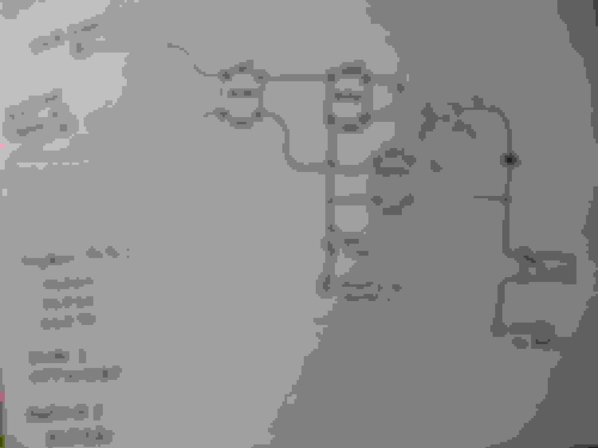
So below is the final circuit design. This has been bench tested and performs fantastic. The actual voltage to the pump on low is around 8.5v because of the forward voltage loss across the diode. I can change this back up to 9v (see below) but will probably keep it where it is. I will be posting pics of this built soon and then installed in the car. All three Crydom relays are mounted to the single large heatsink. The two lower power units are mounted on the sides with thermal adhesive double sided tape. It is expected that none of the relays will put out much heat. I did not list the part number for the DC-DC power supply because that is the one part I am unsure about. I am going to try using this: castle bec
Keep in mind this is a programmable power supply so I can pick different voltages to run the pump at, it is made in the USA and is typically used for RC aircraft servos that are LARGE and expensive. At one airshow I asked a guy how much he had into an A-10 warthog plane and he said 33... as in... 33 grand!! I added a 30mm brushless 12v server fan onto it to keep it cool. It might be fine. Good news is if it dies it won't be when the car is under boost or affect WOT fuel delivery.
So here is the final circuit that allows any BIG fuel pump to be controlled with dual voltage via ECU control:
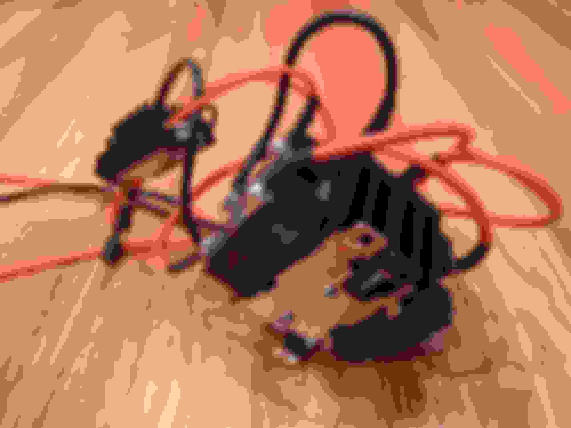
Here are the pics of the 2 liter surge tank and solid state dual voltage pump controller assembled and ready to bolt in. The controller supports fuel pumps sized up to 20 amps !
The two missing inputs on the crydom d1d07 relay are for the two inputs from the car (as described above). The long red wire goes to the pump. The red (with fuse) and black go directly to the battery and the pump itself gets its own ground going to the battery.
In post #30 I showed the relationship between boost and injector duty cycle as it related to the DW350il at 9v.
Here is the plot for boost versus load. With those two graphs it makes sense to just choose a flat 100 load to switch from low to high voltage on the pump.
I have the in tank Walbro 255 set to 9v only..
Here are the pics before I buttoned her up and put the back seat in and trunk plastics. I have been running it for a number of days with everything apart. Damn does that back seat act as a noise suppressor!!! Notice the diode pop riveted to the body. That sucker got hot when it was allowed to float in the open. Which is odd because I am running it at half the rating. It is attached to the car with thermal tape and a rivet and now stays cool to the touch. Nothing else gets even remotely hot, so it should be fine now with it being enclosed. The surge tank is a full 2 liters, which is a tad overkill. The lid for the seat floor had to be cut out obviously for the hoses. I then smoothed the edges and split a small hose length wise to make an edge protector. Don't want that slowly cutting the hoses! I also threw in a Russell performance check valve: 650603. I called tech support. It is a stainless piston with viton oring. So that will work to keep pressure after the engine is turned off. I was able to tuck that under the lid no problem.
these hoses ended up slightly bunched closer once the lid was on. Notice ONE wire from tank pump going to relay. notice relay pop rivetted to car surge tank is tilted which works good for the pickup point I labelled the surge tank to keep my head straight and for future reference.
Two weeks later.... With all plastics and seat cushions back in I am unable to hear the second fuel pump at all even though it isn't submerged. No leaks and it is quick to start thanks to the Russel check valve mentioned above. Nothing gets hot at all (poked my hand in battery access area). Pump switches from 8.5v to 13.5v bat at 100 load (as set in ecu) seamlessly and without using mechanical relays. I also threw in FIC 1200's since I was running at the edge on e85 with id1000's. Now I am around 75% duty cycle max. It was pretty easy to scale them and idle to cruise is +/- 3% on e85. With winter coming I bought an innovate ethanol gauge. So my plan for spring is to switch to open source and ditch the accessport so I can have real flex fuel.
Looking for some input. Tomorrow I am installing the ethanol content sensor.
Should I put it on the INPUT to the surge tank from the main tank.. Thus reading what fuel alcohol content is coming FROM and IN the main tank..
Or should I put it on the RETURN line from the fuel rail? Thus reading what fuel was JUST sent to the engine. Or it doesn't matter a hoot?
Going to do this tomorrow, so looking for some fast advise...