


SMART Quiz (and methanol mapping)


Thread Starter
Evolved Member
iTrader: (20)
Joined: Mar 2003
Posts: 4,941
Likes: 0
From: Danville/Blackhawk, California
 SMART Quiz (win $100 credit and methanol mapping)

New XMap screen. Makes it a bit easier to navigate through all the tables with the buttons at the bottom. Also, thew warning alerts make it so you can just look at this screen while dyno or road testing (not while driving, of course!)
METHANOL

Here's how you do a Methanol control map. This map generates a psuedo 0-5v MAP sensor signal and feeds it into the pump controller box. If you are mimicking a 3bar MAP sensor. 50% in the table would equate to 1.5bar absolute. 100% would equal 3bar. So now you can map the methanol injection with the computer instead of twiddling with onset, ramp-up and max flow knobs. This allows you to provide more methanol when you need it and less when you dont as a function of Load(MAF) and RPM. This table is configured as follows:

The output variable is Anolog 1 Output (AN1O) which is Pin 3 Grey connector.
FUEL

Here's the fuel map. Notice how much leaner it is with the use of Methanol. Also notice that the big enleanments start to happen as the methanol control signal (pseudo-MAP) starts to rise (see methanol map above).
Here's how to set it up:

And now, for the SMART tables. Here's the SMART fuel table:

And here's the setup info:

And here's the threshold map that activates/deactivates the SMART fuel adaptive feature:

And here's the setup info:

Timing

Here's the timing map. Notice how little advance is taken out under high load and how much is even added in during cruise and light load. Remember that, even with zeros in the entire map, the ignition timing is considerably higher than stock due to the extra advance that gets added in due to the huge MAF trim.
Here's the setup info:

And the SMART timing map:

Here's the SMART timing map setup:

And the theshold map that disables/enables the SMART timing feature:

And its setup:

The Quiz
OK... Now here's the fun part. The first person who can explain, lucidly, how the fuel and timing control works, will get a $100 shop credit with us. What needs to be explained is exactly how the logic "flows" (in terms of what inputs and what outputs) from one map to the next.
What you will need to explain is:
1) How does the logic flows between the three fuel maps (Fuel, Smart Fuel and Fuel Thresholds)? And how does this work?
2) How does the logic flows between the three timing maps (Timing, Smart Timing and Timing Thresholds)? And how does this work?
3) Why is the lowest load row in the SMART fuel table full of Zeros?
Come on you Brainiacs!
Cheers!!
Shiv
Last edited by shiv@vishnu; Jul 10, 2005 at 03:54 PM.

Thread Starter
Evolved Member
iTrader: (20)
Joined: Mar 2003
Posts: 4,941
Likes: 0
From: Danville/Blackhawk, California
Nononono.. it's not that hard. Just takes a bit of time to wrap your head around it.
Hint: Look at the input and output variables on each table and make a flow chart.
Hint: Look at the input and output variables on each table and make a flow chart.

Originally Posted by shiv@vishnu
[IMG]h
OK... Now here's the fun part. The first person who can explain, lucidly, how the fuel and timing control works, will get a $100 shop credit with us. What needs to be explained is exactly how the logic "flows" (in terms of what inputs and what outputs) from one map to the next.
What you will need to explain is:
1) How does the logic flows between the three fuel maps (Fuel, Smart Fuel and Fuel Thresholds)? And how does this work?
OK... Now here's the fun part. The first person who can explain, lucidly, how the fuel and timing control works, will get a $100 shop credit with us. What needs to be explained is exactly how the logic "flows" (in terms of what inputs and what outputs) from one map to the next.
What you will need to explain is:
1) How does the logic flows between the three fuel maps (Fuel, Smart Fuel and Fuel Thresholds)? And how does this work?
FUEL input: MAF
Fuel out : user 1
Smart Fuel input: user1
smart fuel out: freq0 out
fuel threshold input: AN2 (wideband)
fuel threshold out: user2
2) How does the logic flows between the three timing maps (Timing, Smart Timing and Timing Thresholds)? And how does this work?
timing in: CAS
timing out: user3
SMART timing in: user3
smart timing out: CAS <-- hey, hey we just modified outself!
timing threshold in: CAS
timing theshold out: user 4
Timing signal comes in, we "smart" it, then send it back out after being threshold checked, yah?
3) Why is the lowest load row in the SMART fuel table full of Zeros?
smart D
Thread Starter
Evolved Member
iTrader: (20)
Joined: Mar 2003
Posts: 4,941
Likes: 0
From: Danville/Blackhawk, California
Originally Posted by donour
There's not a good way to draw this on the forum, but here's the answer. I "kind" of had it in another post.
FUEL input: MAF
Fuel out : user 1
Smart Fuel input: user1
smart fuel out: freq0 out
fuel threshold input: AN2 (wideband)
fuel threshold out: user2
timing in: CAS
timing out: user3
SMART timing in: user3
smart timing out: CAS <-- hey, hey we just modified outself!
timing threshold in: CAS
timing theshold out: user 4
Timing signal comes in, we "smart" it, then send it back out after being threshold checked, yah?
This is low load. MAP should be reading in vacuum (no boost) and the optimal strategy is to keep combustion at stoich. The stock ECU already does this, so the zero's pass the stock signals on with no modification.
smart D
FUEL input: MAF
Fuel out : user 1
Smart Fuel input: user1
smart fuel out: freq0 out
fuel threshold input: AN2 (wideband)
fuel threshold out: user2
timing in: CAS
timing out: user3
SMART timing in: user3
smart timing out: CAS <-- hey, hey we just modified outself!
timing threshold in: CAS
timing theshold out: user 4
Timing signal comes in, we "smart" it, then send it back out after being threshold checked, yah?
This is low load. MAP should be reading in vacuum (no boost) and the optimal strategy is to keep combustion at stoich. The stock ECU already does this, so the zero's pass the stock signals on with no modification.
smart D
Bzzzt... try again

Nice try though

the retry, edits are inline:
Show me the mone---I mean -- the part throttle drivability improvements!
d
Originally Posted by donour
There's not a good way to draw this on the forum, but here's the answer. I "kind" of had it in another post.
FUEL input: MAF
Fuel out : user 1
Smart Fuel input: user1 EDIT: and user2 as a loading variable
smart fuel out: freq0 out
fuel threshold input: AN2 (wideband)
fuel threshold out: user2
EDIT: In other words. The old fuel table generates the base value for SMART fuel. The threshold takes the wideband input and generates loading scaling into for the smart fuel. Then smart fuel spits out a new MAF signal (freq0)
timing in: CAS ---- EDIT: again, loaded by freq0
timing out: user3
SMART timing in: user3 EDIT: loaded by the output of timing threshold, use4
smart timing out: CAS EDIT: my self modifying comment was confusing
timing threshold in: CAS
timing theshold out: user 4
Timing signal comes in, we "smart" it, then send it back out after being threshold checked, yah? EDIT: Again the old-style ( ) timing map generates a baseline timing modification and hands it to SMART timing. SMART timing takes that, and the threshold output, user4, and generates...ahem...REPLICATES a new timing signal.
This is low load. MAP should be reading in vacuum (no boost) and the optimal strategy is to keep combustion at stoich. The stock ECU already does this, so the zero's pass the stock signals on with no modification. EDIT: I'm sticking by this one. The XEDE should still leave very low load fuel control unmolested for the stock cpu to maintain optimal trims. Oh and it might futz with idle control code as well.
smart D
FUEL input: MAF
Fuel out : user 1
Smart Fuel input: user1 EDIT: and user2 as a loading variable
smart fuel out: freq0 out
fuel threshold input: AN2 (wideband)
fuel threshold out: user2
EDIT: In other words. The old fuel table generates the base value for SMART fuel. The threshold takes the wideband input and generates loading scaling into for the smart fuel. Then smart fuel spits out a new MAF signal (freq0)
timing in: CAS ---- EDIT: again, loaded by freq0
timing out: user3
SMART timing in: user3 EDIT: loaded by the output of timing threshold, use4
smart timing out: CAS EDIT: my self modifying comment was confusing
timing threshold in: CAS
timing theshold out: user 4
Timing signal comes in, we "smart" it, then send it back out after being threshold checked, yah? EDIT: Again the old-style (
) timing map generates a baseline timing modification and hands it to SMART timing. SMART timing takes that, and the threshold output, user4, and generates...ahem...REPLICATES a new timing signal.This is low load. MAP should be reading in vacuum (no boost) and the optimal strategy is to keep combustion at stoich. The stock ECU already does this, so the zero's pass the stock signals on with no modification. EDIT: I'm sticking by this one. The XEDE should still leave very low load fuel control unmolested for the stock cpu to maintain optimal trims. Oh and it might futz with idle control code as well.
smart D
Show me the mone---I mean -- the part throttle drivability improvements!
d
Trending Topics

Here is my chart. A pic is worth a thousand words  .
.
1) & 2)
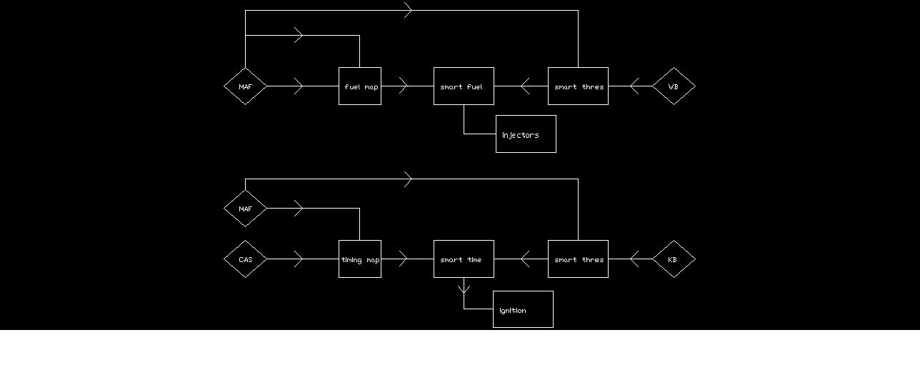
3) The lower rows are zero due to the low load when the car is in vacuum or low boost. The ECU can control those w/ no ill effects. Just like Donour stated.
.1) & 2)
3) The lower rows are zero due to the low load when the car is in vacuum or low boost. The ECU can control those w/ no ill effects. Just like Donour stated.
Originally Posted by jj_008
Here is my chart. A pic is worth a thousand words .
1) & 2)
3) The lower rows are zero due to the low load when the car is in vacuum or low boost. The ECU can control those w/ no ill effects. Just like Donour stated.
.1) & 2)
3) The lower rows are zero due to the low load when the car is in vacuum or low boost. The ECU can control those w/ no ill effects. Just like Donour stated.
EDIT: oh, and download xfig. (http://www.xfig.org)
EDIT2: OH! I just remembered. Doesn't the lastest firmware have crazy idle control features for agressively cam'ed vehicles. If so, then is _that_ why the fuel map is zero'd at the bottom? There is special code for zero load. It's tough to know having only seen this forum, and a few screenshots.
d
Last edited by donour; Jul 10, 2005 at 08:03 PM.

Expanding on jj_008's picture...
For the fuel mapping process the threshold map generates an internal signal that is the wideband's output at high loads, zero at low loads and half of the wideband's output at the transition line, where the axis of the map are the represented in the figure above as inputs (e.g. to prevent chatter).
The fuel map is rather normal other than it's output is an internal signal.
The smart fuel map maps the wideband into the fueling as a function of rpm and thresholded load. The reason the lowest row is zero is that when at low load the threshold map generates a zero which must be carried through to the fueling such that no modification is made via the wideband.
The timing is rather simpler. The threshold map in this case is all zero such that the knock buffer is always employed at any load and rpm. Also as shown above the timing threshold map generates an internal signal that drives the smart timing map. The timing map is very normal with the exception of generating an internal signal that drives the smart timing map. The smart timing map modifying timing as a function of knock and RPM.
For the fuel mapping process the threshold map generates an internal signal that is the wideband's output at high loads, zero at low loads and half of the wideband's output at the transition line, where the axis of the map are the represented in the figure above as inputs (e.g. to prevent chatter).
The fuel map is rather normal other than it's output is an internal signal.
The smart fuel map maps the wideband into the fueling as a function of rpm and thresholded load. The reason the lowest row is zero is that when at low load the threshold map generates a zero which must be carried through to the fueling such that no modification is made via the wideband.
The timing is rather simpler. The threshold map in this case is all zero such that the knock buffer is always employed at any load and rpm. Also as shown above the timing threshold map generates an internal signal that drives the smart timing map. The timing map is very normal with the exception of generating an internal signal that drives the smart timing map. The smart timing map modifying timing as a function of knock and RPM.

Something like this?
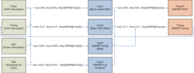
EDIT: added Freq0 as inputs to first calculations, cleaned up mixed up connectors and bad +/* signs, increased font size, GIF'ed it
I left out the methanol stuff, someone can do that for extra credit.
donour and jj_008 got here first, I just wanted to geek out a little with Visio.
EDIT: added Freq0 as inputs to first calculations, cleaned up mixed up connectors and bad +/* signs, increased font size, GIF'ed it
I left out the methanol stuff, someone can do that for extra credit.
donour and jj_008 got here first, I just wanted to geek out a little with Visio.
Last edited by ez76; Jul 10, 2005 at 09:49 PM.
Err, yeah. I misread the input from timing threshold. I think it ahould have been the new knock buffer.
Originally Posted by donour
the retry, edits are inline:
Show me the mone---I mean -- the part throttle drivability improvements!
d
Show me the mone---I mean -- the part throttle drivability improvements!
d