Speed Density Closed Loop Operation Questions
 Jan 16, 2011, 09:05 PM
#1
Speed Density Closed Loop Operation Questions
Background:
I've been tuning my car on SD for the past couple of days. I started with tuning the car in open loop and getting it pretty well dialed in for part throttle and idle. I decided that I would turn on closed loop and see how it did. I made some adjustments to the injector scaling to fix my LTFT and then started tuning the WOT section of the pump gas map at low boost. During my runs around town making WOT pulls on the freeway I noticed that my "lean condition" while pulling away from stop signs was significantly worse now. Prior it would lean out to 16:1 or so and then recover... now it leans out so far the car misfires and nearly died as I entered an intersection. Didn't make me a happy camper.
So I started trying to make fixes (as Aaron@ER had suggested) I went to my MAP VE SD table and increased my Load% value from ~108 to 120 (big change...looking for big results) (MAP 101kpa-> 120 Load%) as well as my Load% value above that... (MAP 61kpa -> 80 Load%)
So basically the map looks like this
61 - 80
101 - 120
HERE'S WHERE MY BIG ENORMOUS QUESTION LIES...
When the closed loop operation has no previous history (no stft or ltft) and its NOT running in open loop. HOW does it determine the injector pulse width to fire at XXXXRPM with XXXLoad% ????
I have 3 guesses
1) its based off the SD VE and MAP tables (has nothing to do with open loop tables) and corrects solely on the surface these tables generate. The low LTFT affects lower flow rates (in this case kpa/MAP values) while the mid LTFT affects higher flow rates (in this case kpa/MAP values) Furthermore, since its only based on the SD VE and MAP tables, you would have to generate a surface that is able to meet the needs of that entire section of the map. This doesn't show to be a problem at high RPM high MAP values since throttling losses among other issues are non-existant. The air flow is very predicable and consistant, where at low flow rates (idle... to transitioning to cruising) has less predictable flow rates.
Where I'm getting with guess 1 (which I think is right, but I hope is wrong) is that there are certain sections of the SD surface which vary from the general surface, which cannot be corrected for quickly enough (by the STFT), and cannot be corrected by the LTFT due to the nature of this particular point in space being positioned too far away from the MAP VE/RPM surface. THEREFORE... making Closed loop fueling with the current Speed Density implementation literally IMPOSSIBLE to perfect.
2) This lean spot has something to do with rate of change of load with respect to engine speed. Basically... one of these seems to make sense. I have not tried either, but in other threads describing this particular lean issue... people have suggested that this does not help.
Async accel vs. RPM Adder
Sync Load Accel Compensation vs. RPM
3) My SD RPM and MAP VE curves are not right.
My assumption is that this lean condition really only happens when I'm at lower engine speeds sub 2k. As the load value (kpa or %) stays the same, but my RPMS increase this lean condition slowly goes away. OR if I rev the engine high enough... and engage the clutch it seems the issues doesn't appear or appears to a lesser degree.
To fix my *theoretical issue #3) I should increase my low(500-1500) RPM VE table and decrease my low(10-40) MAP VE table. Maybe a compensation in this manner would more accurately cover the issue I'm having.
*****
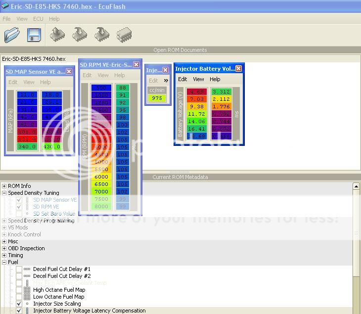
* I stole this from Aaron's thread on how to setup the 1680's... its my actual ROM that he's showing
I'm using these SD settings in v7 Tephra SD, modded by MrFred. Evo 9 w/FIC 1680's
Here is my E85 settings... my current RPM and MAP VE tables are very similar except the the changes I discussed that i tried above...and the low MAP VE Load % are reduced to lean out the low load areas.
Thank you in advance. This has been particularly frustrating for me.
-Eric
I've been tuning my car on SD for the past couple of days. I started with tuning the car in open loop and getting it pretty well dialed in for part throttle and idle. I decided that I would turn on closed loop and see how it did. I made some adjustments to the injector scaling to fix my LTFT and then started tuning the WOT section of the pump gas map at low boost. During my runs around town making WOT pulls on the freeway I noticed that my "lean condition" while pulling away from stop signs was significantly worse now. Prior it would lean out to 16:1 or so and then recover... now it leans out so far the car misfires and nearly died as I entered an intersection. Didn't make me a happy camper.
So I started trying to make fixes (as Aaron@ER had suggested) I went to my MAP VE SD table and increased my Load% value from ~108 to 120 (big change...looking for big results) (MAP 101kpa-> 120 Load%) as well as my Load% value above that... (MAP 61kpa -> 80 Load%)
So basically the map looks like this
61 - 80
101 - 120
HERE'S WHERE MY BIG ENORMOUS QUESTION LIES...
When the closed loop operation has no previous history (no stft or ltft) and its NOT running in open loop. HOW does it determine the injector pulse width to fire at XXXXRPM with XXXLoad% ????
I have 3 guesses
1) its based off the SD VE and MAP tables (has nothing to do with open loop tables) and corrects solely on the surface these tables generate. The low LTFT affects lower flow rates (in this case kpa/MAP values) while the mid LTFT affects higher flow rates (in this case kpa/MAP values) Furthermore, since its only based on the SD VE and MAP tables, you would have to generate a surface that is able to meet the needs of that entire section of the map. This doesn't show to be a problem at high RPM high MAP values since throttling losses among other issues are non-existant. The air flow is very predicable and consistant, where at low flow rates (idle... to transitioning to cruising) has less predictable flow rates.
Where I'm getting with guess 1 (which I think is right, but I hope is wrong) is that there are certain sections of the SD surface which vary from the general surface, which cannot be corrected for quickly enough (by the STFT), and cannot be corrected by the LTFT due to the nature of this particular point in space being positioned too far away from the MAP VE/RPM surface. THEREFORE... making Closed loop fueling with the current Speed Density implementation literally IMPOSSIBLE to perfect.
2) This lean spot has something to do with rate of change of load with respect to engine speed. Basically... one of these seems to make sense. I have not tried either, but in other threads describing this particular lean issue... people have suggested that this does not help.
Async accel vs. RPM Adder
Sync Load Accel Compensation vs. RPM
3) My SD RPM and MAP VE curves are not right.
My assumption is that this lean condition really only happens when I'm at lower engine speeds sub 2k. As the load value (kpa or %) stays the same, but my RPMS increase this lean condition slowly goes away. OR if I rev the engine high enough... and engage the clutch it seems the issues doesn't appear or appears to a lesser degree.
To fix my *theoretical issue #3) I should increase my low(500-1500) RPM VE table and decrease my low(10-40) MAP VE table. Maybe a compensation in this manner would more accurately cover the issue I'm having.
*****
* I stole this from Aaron's thread on how to setup the 1680's... its my actual ROM that he's showing
I'm using these SD settings in v7 Tephra SD, modded by MrFred. Evo 9 w/FIC 1680's
Here is my E85 settings... my current RPM and MAP VE tables are very similar except the the changes I discussed that i tried above...and the low MAP VE Load % are reduced to lean out the low load areas.
Thank you in advance. This has been particularly frustrating for me.
-Eric
Last edited by R/TErnie; Jan 16, 2011 at 09:08 PM.
 Jan 17, 2011, 06:05 AM
#2
I got rid of that lean issue starting out by increasing fuel in the open loop table in the relevant load/RPM ranges (around 70 load and around 1500-1700 rpm). I don't know what the problem is necessitating that adjustment, but I know of at least two or three other people who have done the same fix.
Jan 17, 2011, 06:22 AM
#3
Ok this morning I reflashed the car with the following changes.
Richened up the open loop map in the problem area by a solid 2.0 AFR
Increased the MAP VE in the problem area by about 5 or so (from the map shown above)
Reduced the MAP VE in the lower kpa cells.
Increased the RPM VE in the problem area RPMS by 1.
I put the car into open loop to evaluate the overall tune.
I was able to reduce the problem area down to 15:1 AFR, but for most any other time on throttle at low RPMS I'm at 12:1. On the way to work I put the car in 4th gear and loaded the car to 50, 60, 70, 80, 90, 100, 110, 120 load @ 1250, 1500, and 1750 RPMS. I noticed that at about 105 load or so is when the AFR went to 15:1. So i went back to my open loop table and enrichened that area by about 1-2 AFR.
I haven't been out to test it again, since I just flashed that fix as I was in the parking lot at work.
Last edited by R/TErnie; Jan 17, 2011 at 08:39 AM.
Jan 17, 2011, 09:43 AM
#4
The majority of the fuel pulse calculation is described in my fuel pulse thread. As noted in that thread, there are a few contributions that I don't fully understand, but I think I explain when they can make a difference and when they can't.
If you're asking where the ECU looks up AFRMAP in closed loop, it looks it up at a 1D value that is not even a "table". Its just a set value in the code of 0x80 = 14.7:1 target. However, the story of AFRMAP lookup is not as simple "read from 1D value in closed loop", and "read from fuel table" in open loop. In the subroutine that selects AFRMAP, there is actually at least one other option for determining AFRMAP. Its been a few years since I've been through it, and I don't recall the conditions that send it down the alternative path.
If you're asking where the ECU looks up AFRMAP in closed loop, it looks it up at a 1D value that is not even a "table". Its just a set value in the code of 0x80 = 14.7:1 target. However, the story of AFRMAP lookup is not as simple "read from 1D value in closed loop", and "read from fuel table" in open loop. In the subroutine that selects AFRMAP, there is actually at least one other option for determining AFRMAP. Its been a few years since I've been through it, and I don't recall the conditions that send it down the alternative path.
Jan 17, 2011, 09:59 AM
#5
Ok Mychailo,
But if the target is 14.7 whenever we're in closed loop for all RPM's and Loads that fall within the bounds of Closed Loop Control... How does governor correct for different RPMS and Loads? Reason I ask this is there can't be a blanket correction of "add 5% everywhere and its perfect" Some might suggest that the short term fuel correction could be used to dial in the strange areas of the map, BUT the short term fuel correction cannot react fast enough to fix this particular lean spot.
when i think of closed loop... I think of a PID controller that has a setpoint and feedback. How is the setpoint determined? I guess you're telling me the setpoint is set at 14.7 by 0x80. Then my next question is... what is the capability of the ECU to store corrections (I assume this is LTFT) based on RPM and Load? If LTFT is the ECU's only ability to store corrections (make changes to the setpoint more or less... because that's what its really doing) then we only have Low, Mid, and High correct? And those thresholds (with built in hysteresis i suspect) are defined by Hz (and for SD I suspect that they're converted into some combination of RPM vs. Load to estimate the Hz?) If that's the case then the SD VE and RPM maps would affect the transition of low, mid, and high for closed loop operation.
Maybe I'm babbling now.
Last edited by R/TErnie; Jan 17, 2011 at 10:01 AM.
Jan 17, 2011, 10:16 AM
#6
Babbling? You?
The STFT and LTFTs are it for closed loop trims. Nothing else hiding in the ECU. Feedback is of course the front O2 sensor, but you know that. I've not develed into the subroutines where the trim values are calculated. Your assumptions about the LTFT boundary variable and the effect of SD on the position of the boundaries are correct.
One thing to consider modifying is the MAF scaling table. Its a similar knob to the VE scaling. When doing SD in closed loop, have you been monitoring AFRMAP to ensure that its holding at 14.7:1? Since you are using FTT for IAT, you could calc and log both SD load and MAF load to see what's happening in the problem spot.
Trending Topics
Jan 17, 2011, 11:27 AM
#8

Hopefully SD 2.0 and a 3D VE table will end that hassle.
That's good advice. If you had logs of the MAF through this range it would be ideal to see how well your SD tune is mimicking the MAF tune.
Jan 17, 2011, 02:30 PM
#9
Interesting... I didn't get this... until you commented on it Eric...
"Since you are using FTT for IAT, you could calc and log both SD load and MAF load to see what's happening in the problem spot."
Just to double check...you're suggesting putting back on my MAF sensor to check to see how well I'm correlating.
What does your sub 100kpa and sub 4krpm SD VE tables look like Eric?
thank you guys! I'm starting to see the light.
Jan 17, 2011, 06:49 PM
#11
I'll try to take a look at my tuning laptop tomorrow if I get a chance. I haven't touched it for months. I'm looking through what I have on this computer, and this is what I found. I don't know if this was my final tune or not.


When I was on SD, though, the tune was pretty much spot on and I really didn't have any issues. I matched my MAF load to SD load as well as I could and used Excel to make a 3D VE map out of the two VE tables and went from there.
I'm not on SD now, though. I didn't like the heat soaked MAT sensor issue on warm start and didn't want to band-aid fix it. And since I just moved to CA, I had to sell my Amsoil filter and Dejon intake anyway and put back on the stock box. So, since I was putting a few things back to stock, I figured, until a patch can be made to handle the heat soak issue, I'll stay on MAF for now.
Jan 17, 2011, 07:03 PM
#12
why not put your MAT/IAT sensor on your charge pipe like Mychailo did? unless your charge pipes are getting heat soaked..
I played with it some more today. I set my entire open loop section to 14.7 target AFR... then started playing with the RPM VE and MAP VE. Mine turned out looking different than yours by a bit, but I think it works well.
Idle is much better, cruise is better, tip in, and tip out is better... it pretty much does what I want. The interesting part about looking at other people's maps... the lowest RPMS are affected by their latency calcs as well as their injector scaling... the higher RPMs and loads can vary based on people's preference for AFR.
Thank you guys for the help. Its coming along nicely now
Last edited by R/TErnie; Jan 17, 2011 at 07:06 PM.
Jan 18, 2011, 07:48 AM
#15
Yep.
It wasn't a huge problem, though. Just an annoyance to me. Having a lean few seconds after start if the car sat for a while. Some people probably wouldn't even care, but for my daily driver, it just wasn't right and I knew it.
I don't know if I posted logs of it, but it definitely was happening. The MAT would slowly creep up after the car was shut off due to the underhood temps. It obviously will reach a peak and come back down, depending on several variables such as ambient temp, time waited, etc, etc, but it still was an issue that needed to be fixed with some kind of patch.
Last edited by l2r99gst; Jan 18, 2011 at 07:53 AM.