4G69 Tear Down Detail

 Feb 9, 2015, 06:12 AM
#17
If I get time today I have two new chapters to post as well.
Feb 9, 2015, 10:34 AM
#18
>: CHAPTER 5 :<
:// Sensors
So I thought it would be a good idea to make a chapter focused on the sensors still left on the engine. So we'll start at the top and work our way down.
Back in chapter 1 we were supposed to remove the Camshaft Position Sensor and its components. I skipped showing that back then so lets see it now.
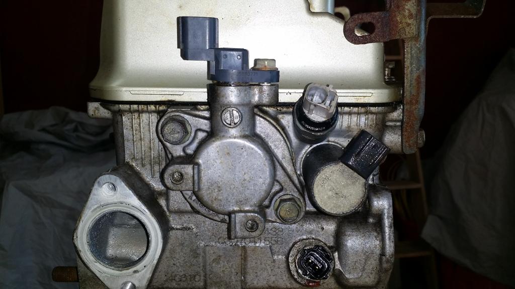
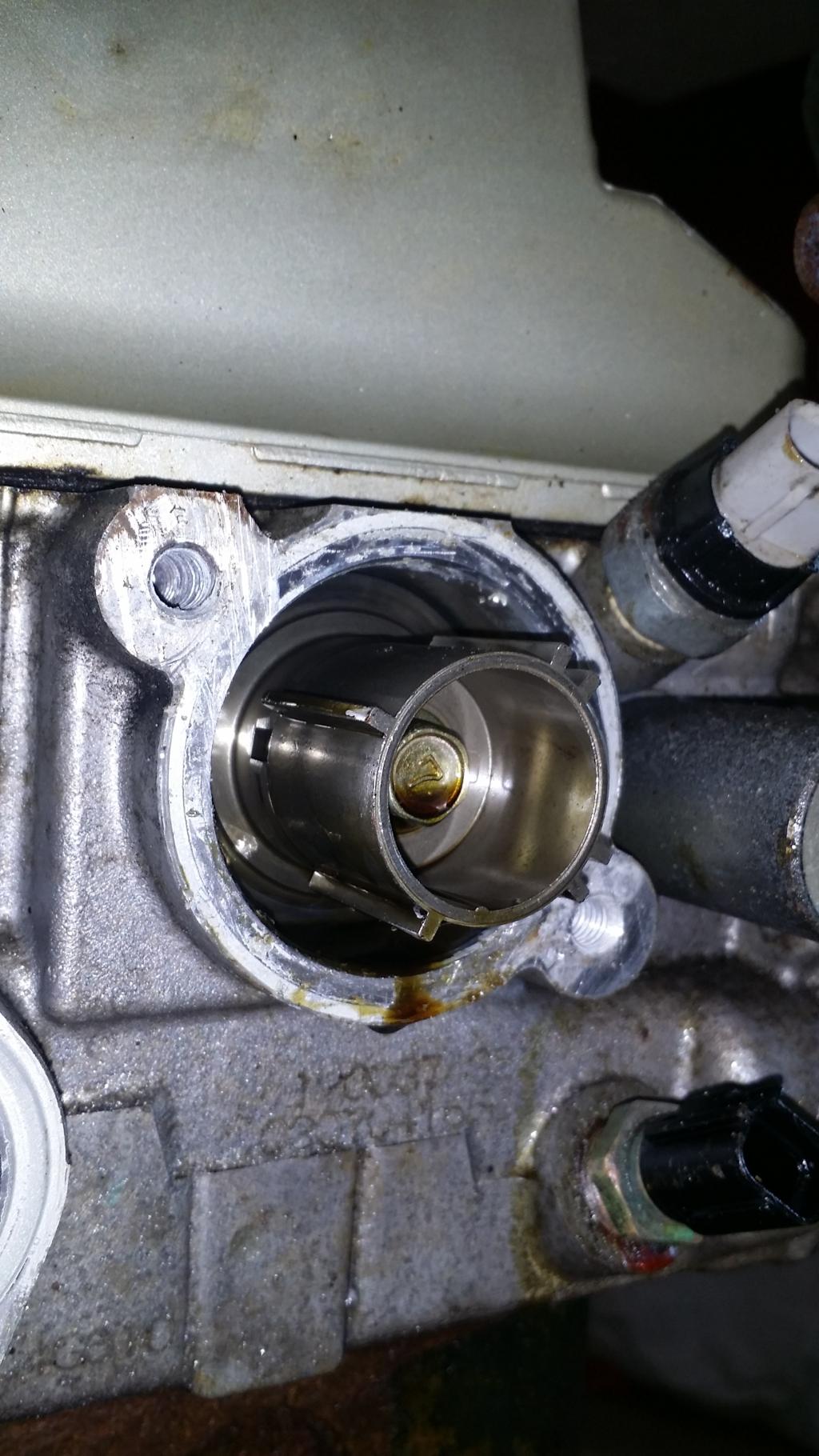
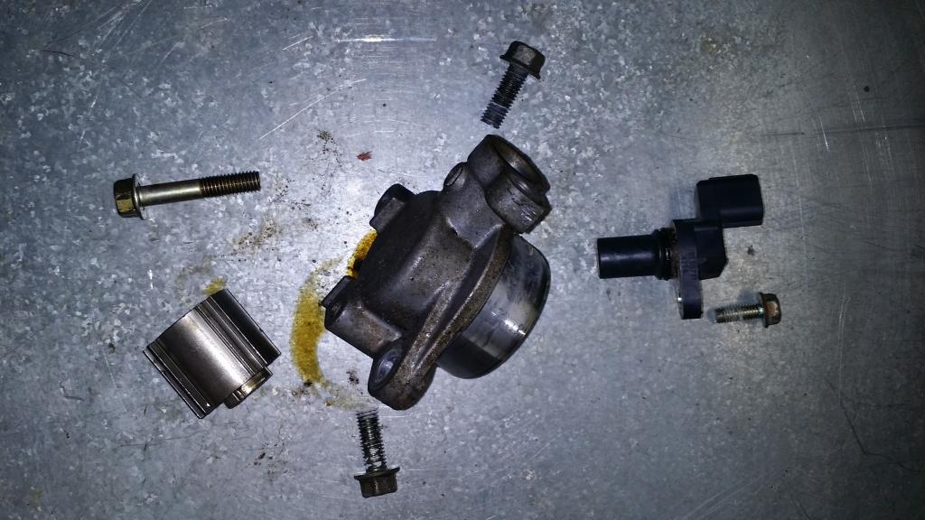
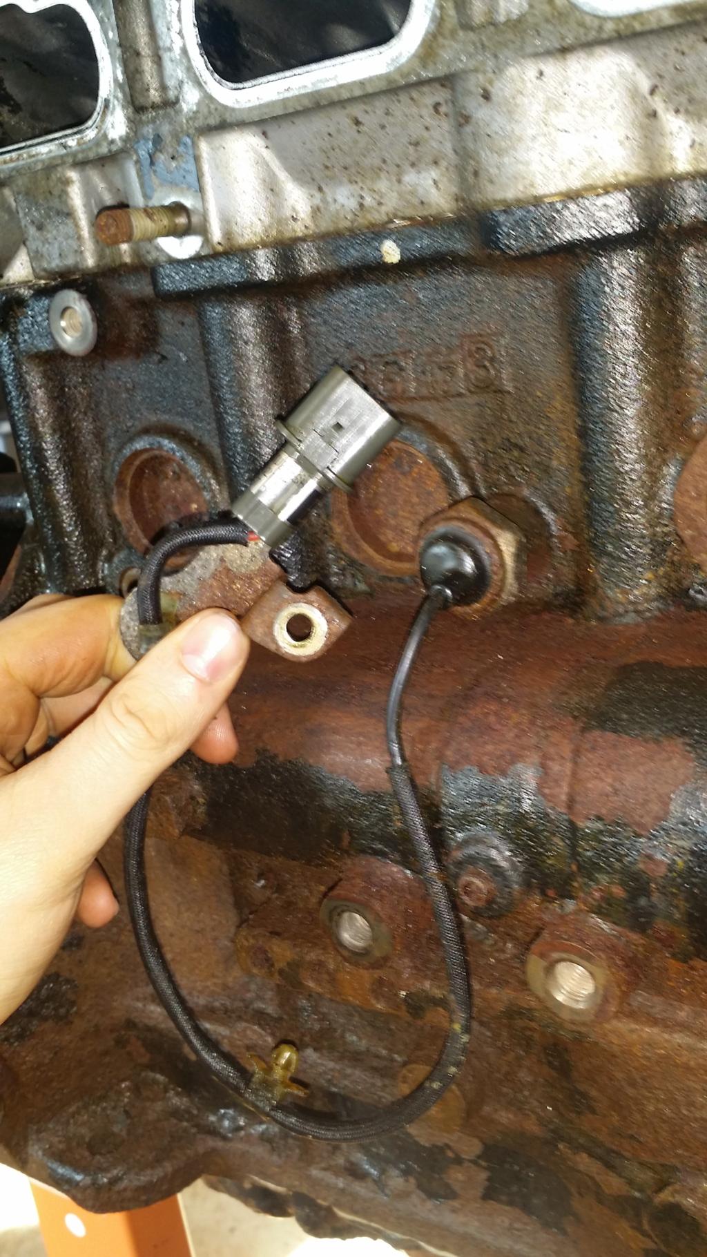
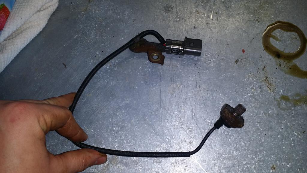
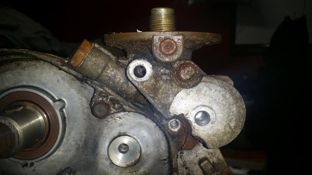
So we see there are quite a few sensors here. We are focused on the camshaft positon sensor it is the one sitting on the highest point. We will also take off the sensing cylinder and support while we are removing things. To pull out the Sensor use a 10mm socket to remove the bolt then the sensor should come right up and out. Then to remove the support that the sensor was inside of we will need a 12mm socket to remove the bolts holding it to the head. Then if your support is stuck in anything like mine its probably held on with some sort of RTV and you'll need a chisel to loosen it from the head. Then I just had to work it back and forth and round until i could pull it out by hand. Now we are supposed to remove the cylinder. You'll need a 12mm socket inside the Cylinder to loosen the bolt. But to keep the Cam from turning I used a 17mm socket on the sprocket side of the head to hold it all still. Also I ended up having to use some extensions cause there is a bit of torque on this bolt.
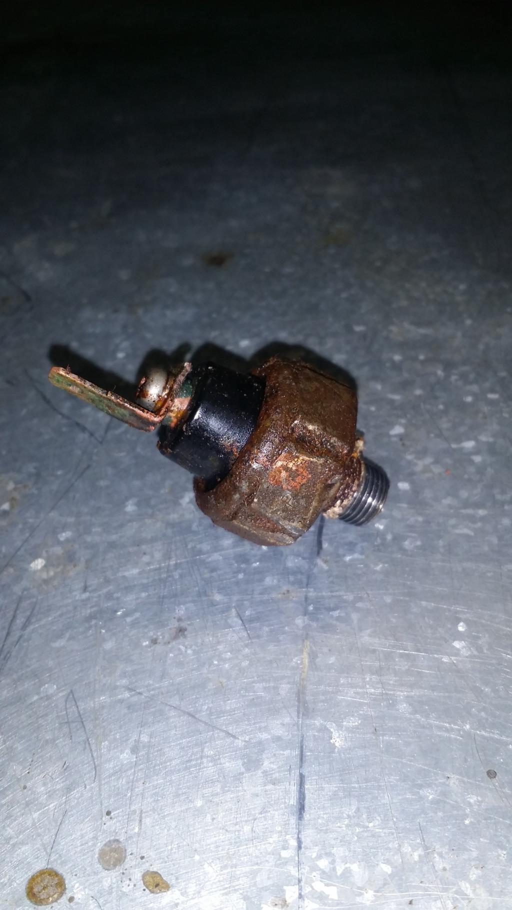
Next up is the gray sensor from the top picture. This is one of two Engine Oil Pressure Switches. We will do the second immediately following this one. To get this sensor off I used an adjustable wrench and had to work as some weird angles. But it eventually came out.
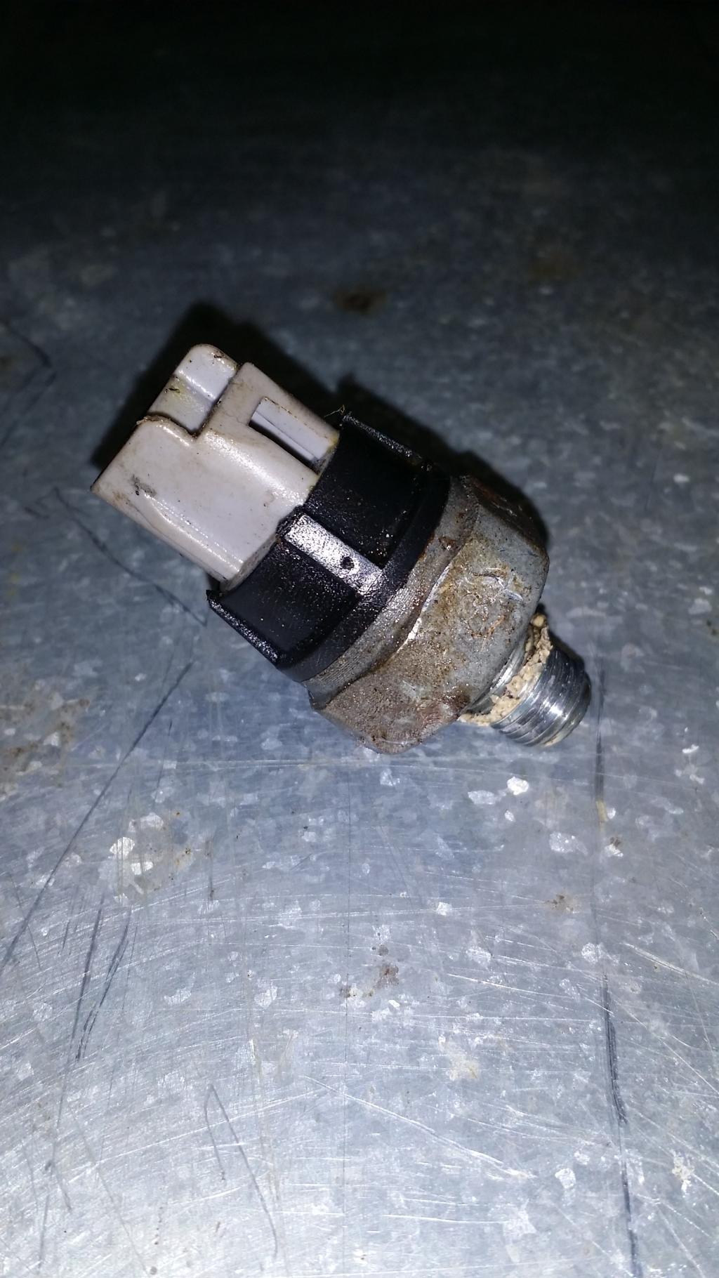
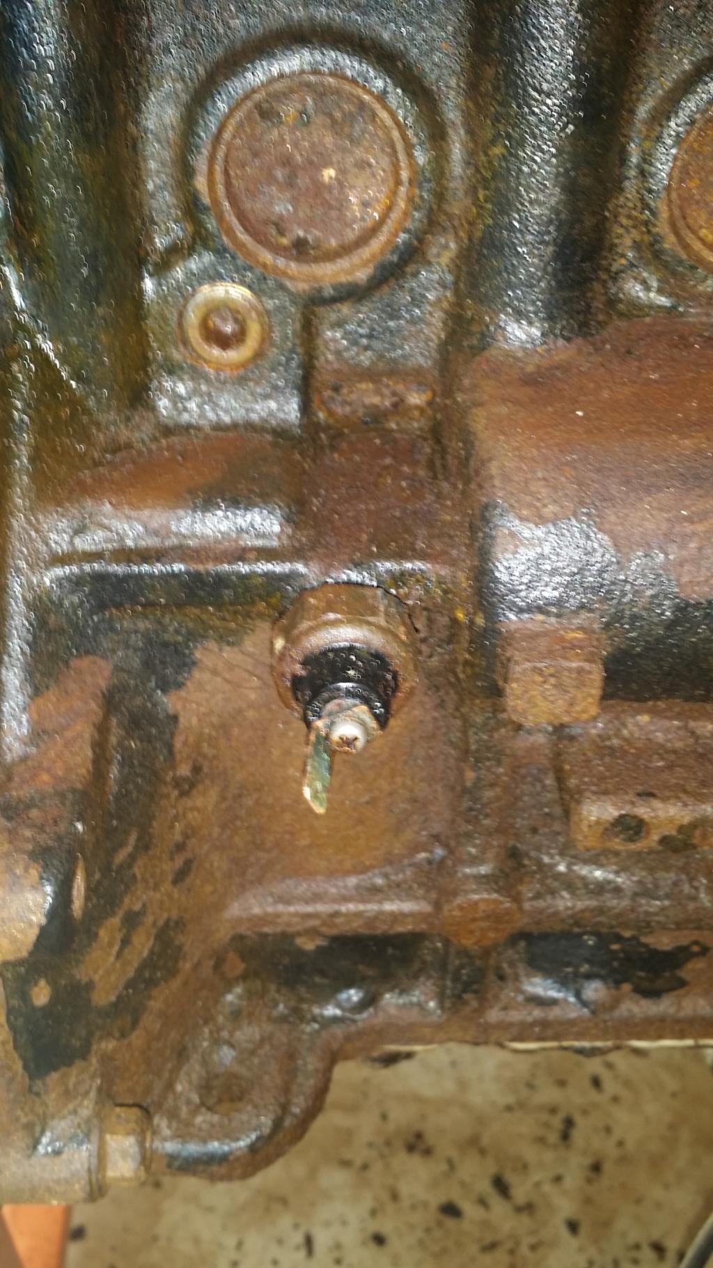
The other Engine Oil Pressure Switch is on the back of the block under the freeze plug closest to the tranny. Again I dont have any OEM Mitsubishi super secret tools so I just used the adjustable again.
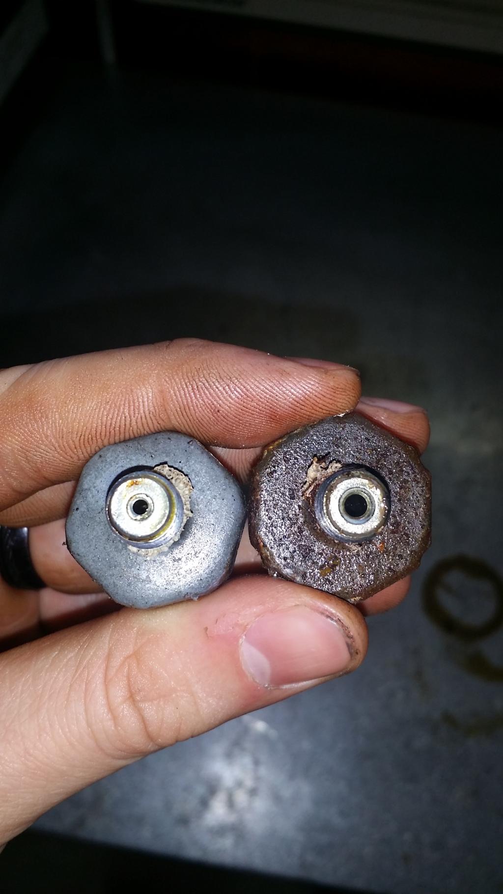
I was curious what the difference was and flipping them over you can see this.
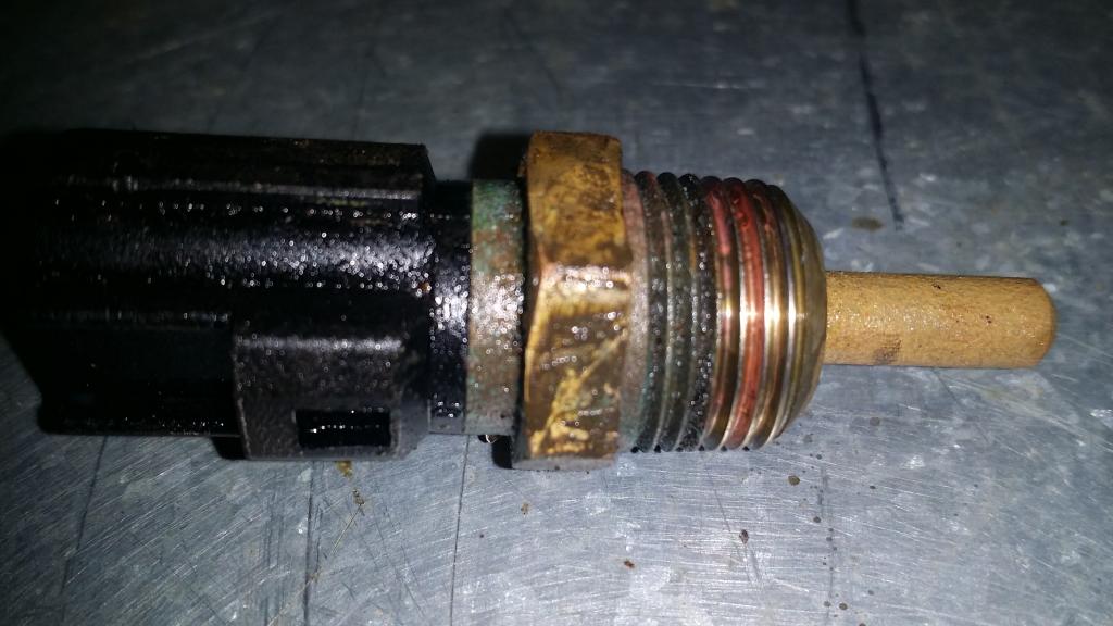
Now if we refer to the top picture again we will be removing the lowest sensor, which is the coolant temp sensor. Again I just used the adjustable to loosen it then removed it by hand.
Next we will remove the Knock sensor from the back of the engine block. We mentioned this one in the Intake Manifold chapter. Lets go ahead an remove it now. Break out the trusty adjustable for this one as well.
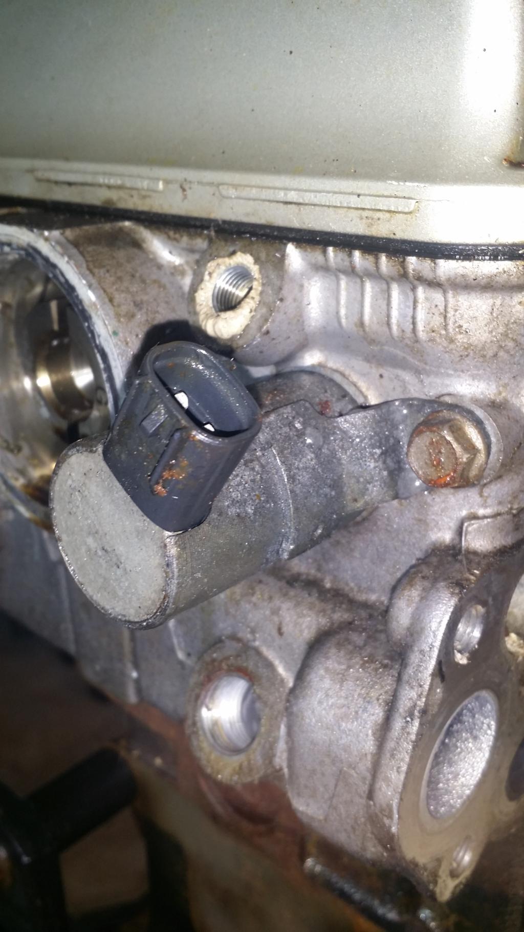
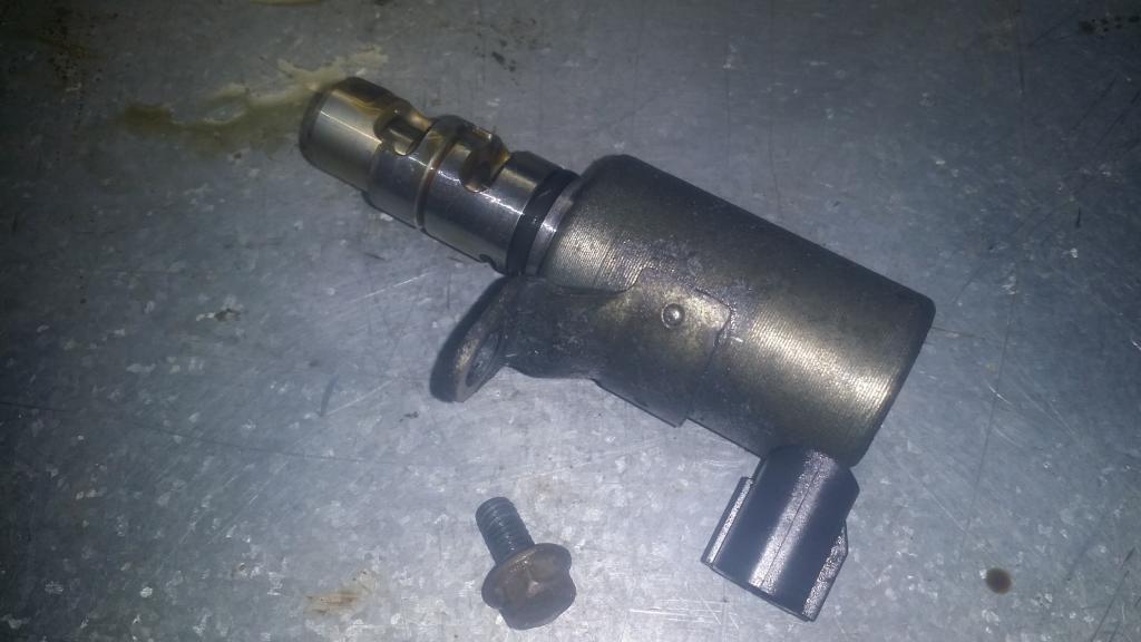
Last one. This one isnt so much of a sensor as it is a valve, but the head cant be removed unless its out. This is the Engine Oil Control Valve. Holding it on is a single 10mm bolt. Takes a bit of twisting and pulling but it will eventually pop out.
And thats all for this chapter. Next chapter, we behead the 4g69!
:// Sensors
So I thought it would be a good idea to make a chapter focused on the sensors still left on the engine. So we'll start at the top and work our way down.
Back in chapter 1 we were supposed to remove the Camshaft Position Sensor and its components. I skipped showing that back then so lets see it now.
So we see there are quite a few sensors here. We are focused on the camshaft positon sensor it is the one sitting on the highest point. We will also take off the sensing cylinder and support while we are removing things. To pull out the Sensor use a 10mm socket to remove the bolt then the sensor should come right up and out. Then to remove the support that the sensor was inside of we will need a 12mm socket to remove the bolts holding it to the head. Then if your support is stuck in anything like mine its probably held on with some sort of RTV and you'll need a chisel to loosen it from the head. Then I just had to work it back and forth and round until i could pull it out by hand. Now we are supposed to remove the cylinder. You'll need a 12mm socket inside the Cylinder to loosen the bolt. But to keep the Cam from turning I used a 17mm socket on the sprocket side of the head to hold it all still. Also I ended up having to use some extensions cause there is a bit of torque on this bolt.
Next up is the gray sensor from the top picture. This is one of two Engine Oil Pressure Switches. We will do the second immediately following this one. To get this sensor off I used an adjustable wrench and had to work as some weird angles. But it eventually came out.
The other Engine Oil Pressure Switch is on the back of the block under the freeze plug closest to the tranny. Again I dont have any OEM Mitsubishi super secret tools so I just used the adjustable again.
I was curious what the difference was and flipping them over you can see this.
Now if we refer to the top picture again we will be removing the lowest sensor, which is the coolant temp sensor. Again I just used the adjustable to loosen it then removed it by hand.
Next we will remove the Knock sensor from the back of the engine block. We mentioned this one in the Intake Manifold chapter. Lets go ahead an remove it now. Break out the trusty adjustable for this one as well.
Last one. This one isnt so much of a sensor as it is a valve, but the head cant be removed unless its out. This is the Engine Oil Control Valve. Holding it on is a single 10mm bolt. Takes a bit of twisting and pulling but it will eventually pop out.
And thats all for this chapter. Next chapter, we behead the 4g69!
Feb 9, 2015, 10:40 AM
#19
>: CHAPTER 6 :<
:// Cylinder Head Removal
It is finally time to sever the head from this 4g69 monster. This is kind of a moment of truth for me. This will show me the exact condition of the inside of my engine and let me know how I need to proceed from here for my build. Lets get right to it.
I didnt get a picture of this part but I removed the brackets that you use to lift the engine. This involved using a 12mm socket on the bolts that hold the brackets to the head. Nothing crazy im sure you can figure that out if youve made it this far.
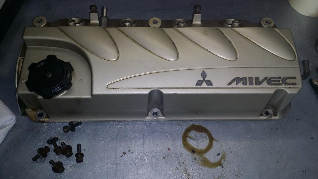
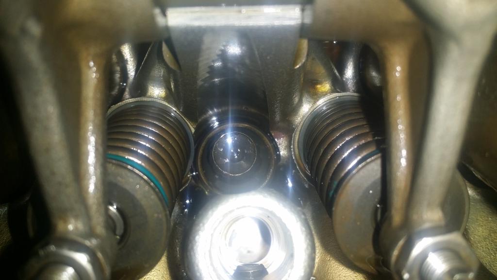
First we need to remove the valve cover. It is held in place by six 10mm bolts and a small stack of washers. Remove those and lift the cover off. It may be stick somewhat, there is a gasket holding it on.
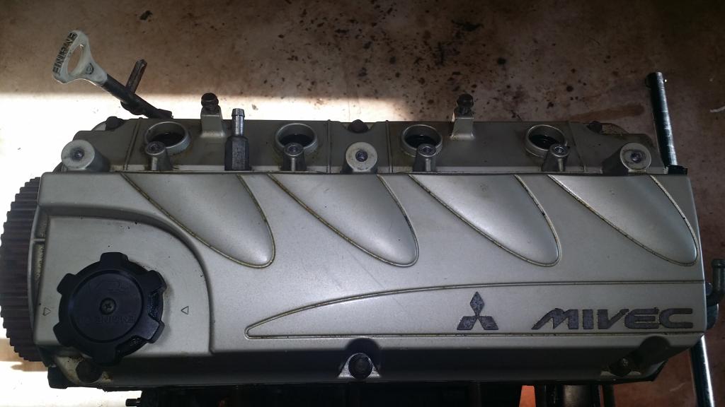
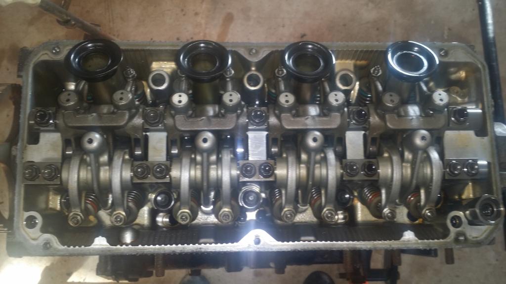
Now we have a nice view of our valvetrain. This is where all that Mivec magic takes place.
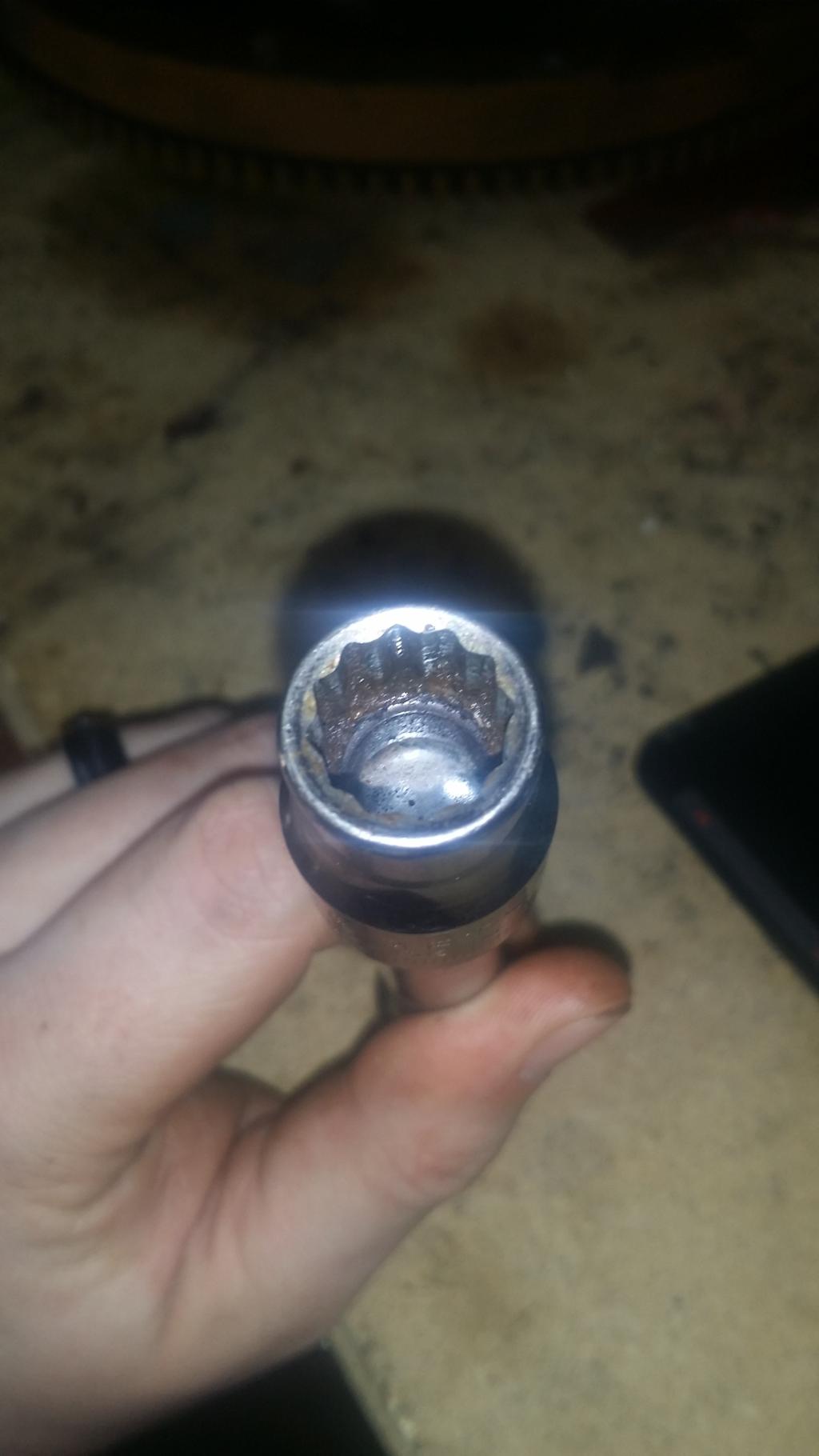
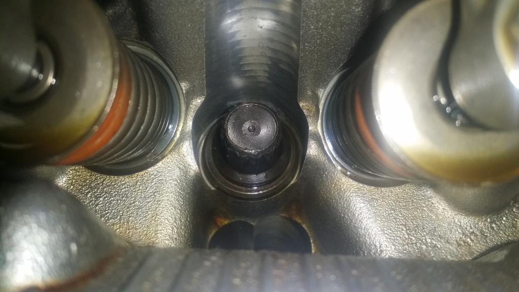
Now to get the head free of the block we need to remove the head studs. There are ten. To get them off use a twelve point 12mm socket, on an extension. Mitsu of course has a special tool for this but this works perfectly well. Looks like this.
And here is what you are looking for inside the head. And if you havent already, now is a good time to remove your spark plugs.
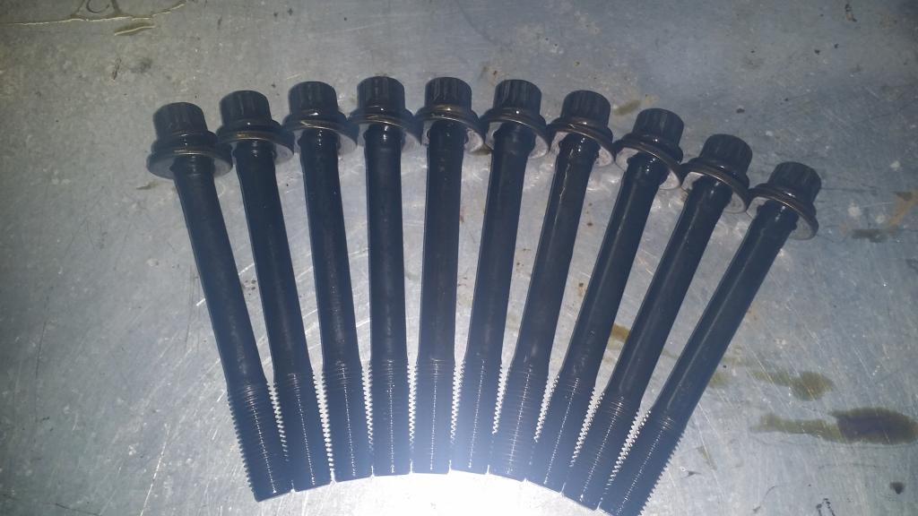
These will have quite a bit of torque on them to turn slowly lets not hulk it and screw something up. To do this I used a torque wrench so I could more easily manage the pressure i was using. Service manual also recommends installing the bolts from inside out working on opposite sides as you go. So lets do the opposite to remove it. We will start as the exhaust side bolt and the timing belt end, then go to the intake side on the sensor side, then back and forth till we reach the center.
Bolts removed.
Here goes the head...
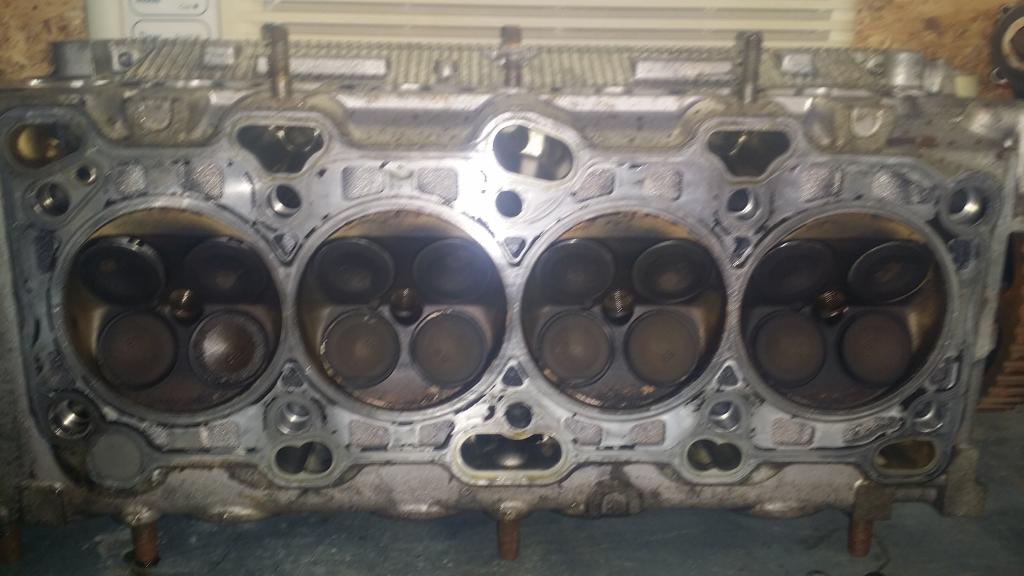
Well some of the valves dont look like they close all the way. To be expected.
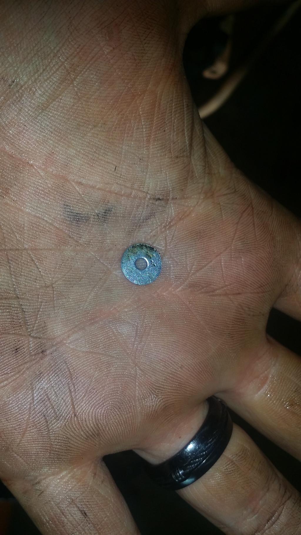
Found that in cylinder 1. not sure what it is or where it came from...
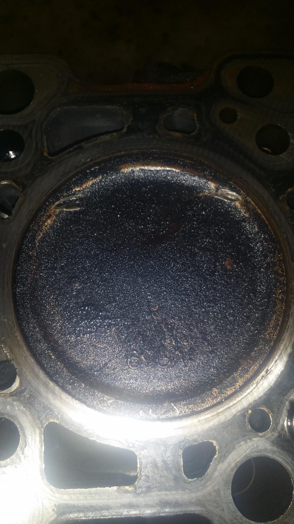
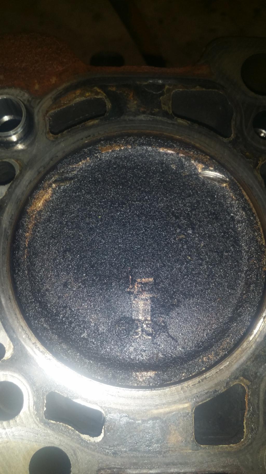
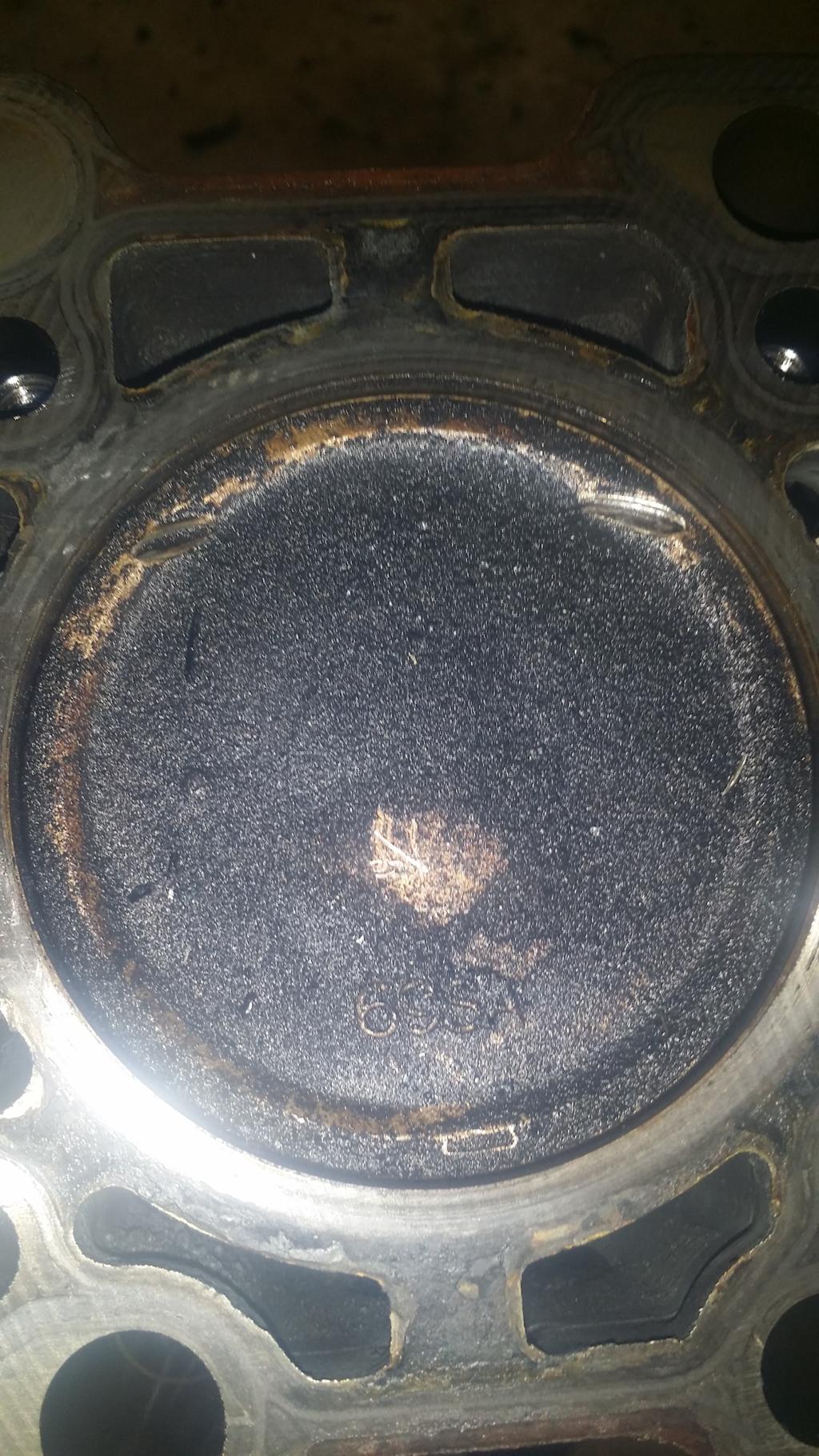
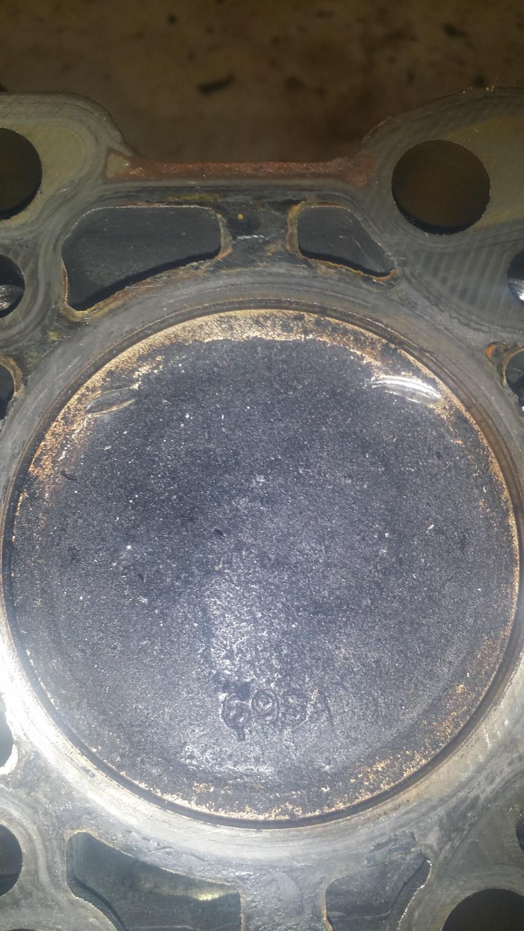
And as you can see every piston has made contact with the valves and has been scarred by them. Kinda makes me wonder if I should bother reusing them or not...
Well thats all it took for this chapter. Next we will remove the oil pan and take a look at things on the bottom end.
:// Cylinder Head Removal
It is finally time to sever the head from this 4g69 monster. This is kind of a moment of truth for me. This will show me the exact condition of the inside of my engine and let me know how I need to proceed from here for my build. Lets get right to it.
I didnt get a picture of this part but I removed the brackets that you use to lift the engine. This involved using a 12mm socket on the bolts that hold the brackets to the head. Nothing crazy im sure you can figure that out if youve made it this far.
First we need to remove the valve cover. It is held in place by six 10mm bolts and a small stack of washers. Remove those and lift the cover off. It may be stick somewhat, there is a gasket holding it on.
Now we have a nice view of our valvetrain. This is where all that Mivec magic takes place.
Now to get the head free of the block we need to remove the head studs. There are ten. To get them off use a twelve point 12mm socket, on an extension. Mitsu of course has a special tool for this but this works perfectly well. Looks like this.
And here is what you are looking for inside the head. And if you havent already, now is a good time to remove your spark plugs.
These will have quite a bit of torque on them to turn slowly lets not hulk it and screw something up. To do this I used a torque wrench so I could more easily manage the pressure i was using. Service manual also recommends installing the bolts from inside out working on opposite sides as you go. So lets do the opposite to remove it. We will start as the exhaust side bolt and the timing belt end, then go to the intake side on the sensor side, then back and forth till we reach the center.
Bolts removed.
Here goes the head...
Well some of the valves dont look like they close all the way. To be expected.
Found that in cylinder 1. not sure what it is or where it came from...
And as you can see every piston has made contact with the valves and has been scarred by them. Kinda makes me wonder if I should bother reusing them or not...
Well thats all it took for this chapter. Next we will remove the oil pan and take a look at things on the bottom end.
Feb 10, 2015, 05:12 AM
#20
hey...if you say there's a stack of washers on your valve cover bolt/s...that may be where that one came from...somehow maybe you managed to drop it into the open intake or exhaust port and slid all the way into the cylinder...and that's y it looks so new and undamaged...
(unless it's too small for the valve cover bolts...
then Im still confused..)
I remember when I did my valve cover there were no stacked washers...(maybe one per bolt at most, but definetly no stacks..)
(unless it's too small for the valve cover bolts...
then Im still confused..)
I remember when I did my valve cover there were no stacked washers...(maybe one per bolt at most, but definetly no stacks..)
Feb 10, 2015, 05:57 AM
#21
Nah that thing is way too small for that. Im starting to wonder if it fell out of one of the coolant or oil lines when I lifted the head off. Im at a loss as to where that could have came from. I inspected the piston and cylinder head and there is no marking that looks like it would have been in there when the engine was last running, plus I figured something that small would have been blown out of the exhaust anyway. So Im just going to ignore it for now.
Still slightly concerned about the pistons but Cranswick helped to ease that tension. Im just going to clean them up and run them anyway.
Also still needing to find a good cylinder head shop. I found a place near where I work but it didnt look like they had anything newer than a 1970's V8 engine in their shop so I was a bit thrown off by that. Google said there is another shop down in lexington that I might have to check out.
Feb 11, 2015, 08:21 PM
#23
>: CHAPTER 7 :<
:// Oil Pan and Pump
Alright here we are. Everything is gone except for the oil system and the pistons and crankshaft. And since I am not planning to remove the crankshaft and pistons then this will be the last chapter of my disassembly.
If you would like for me to go back and give you more details on anything at this point them please ask and I will make a follow up Chapter to wrap everything up. I wouldnt mind to go back and get you bolt/nut sizes on the stuff I didnt disassemble if anyone is interested. I'll also go back and try to get screenshots from the FSM so that you all can see the diagrams of what all has been done. Plus I think they will be a handy reference to have on the site. As long as our mods are ok with it.
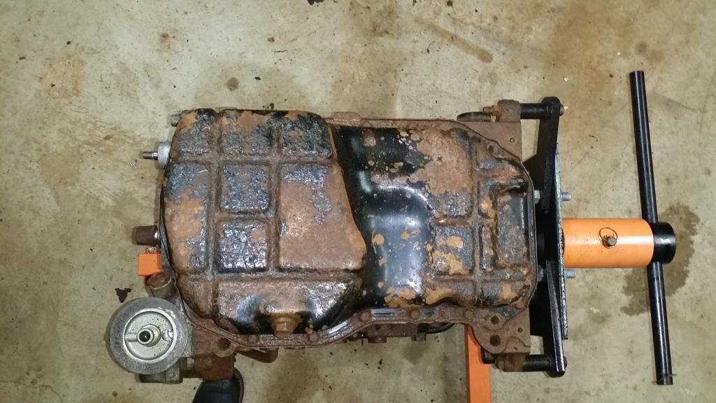
Anyway lets get into this. FSM says Drain plug and Gasket first, Im going to leave them in so I can set the pan on my work bench and it not leak oil. Next is the Oil filter which we removed a long time ago, and I hope you already know how to remove... lol! Item 4 is the oil pan. Now we can get started. To remove the pan you need to take out nineteen 10mm bolts from around the pan. Mine are obviously rusty so im going to take some time on them, hopefully none break.
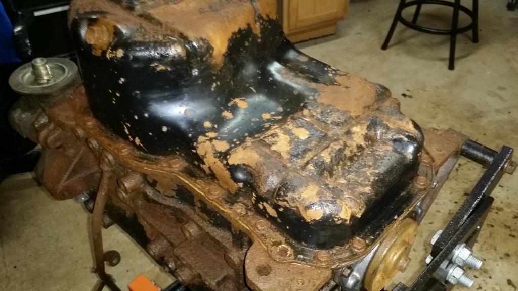
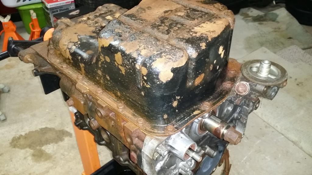
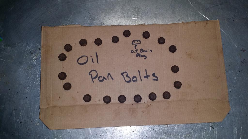
To help me keep track of all the bolts and where they go since some of them are shorter than others. I found me a piece of cardboard and poked the bolts thru in the shape of the pan. That way when it goes back together there's no questioning what goes where.
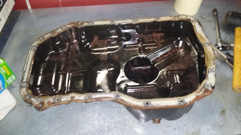
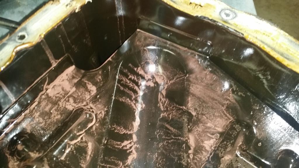
Now the oil pan should be mated to the block using some RTV so it wont just lift off. I used a chisel and gently worked my way around until it was loose enough to lift off. Any idea what this pink stuff is?
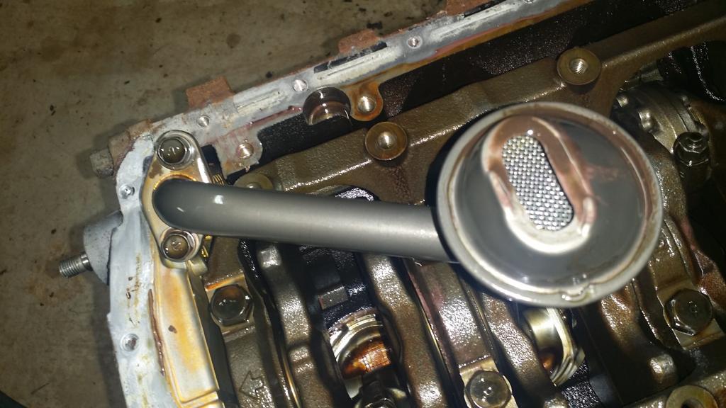
And here we can see our crankshaft, con rods, underside of the pistons, and oil pickup.
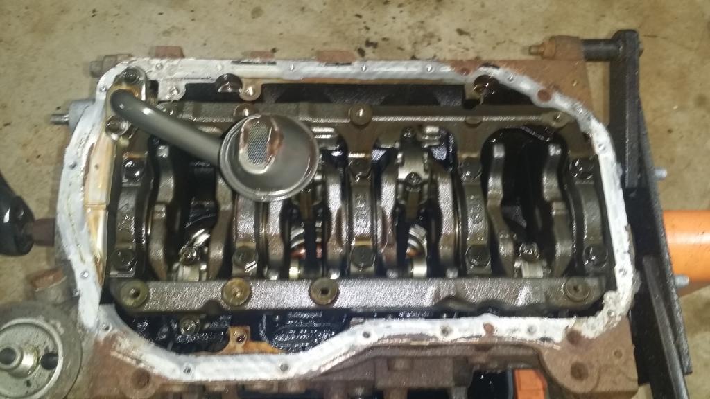
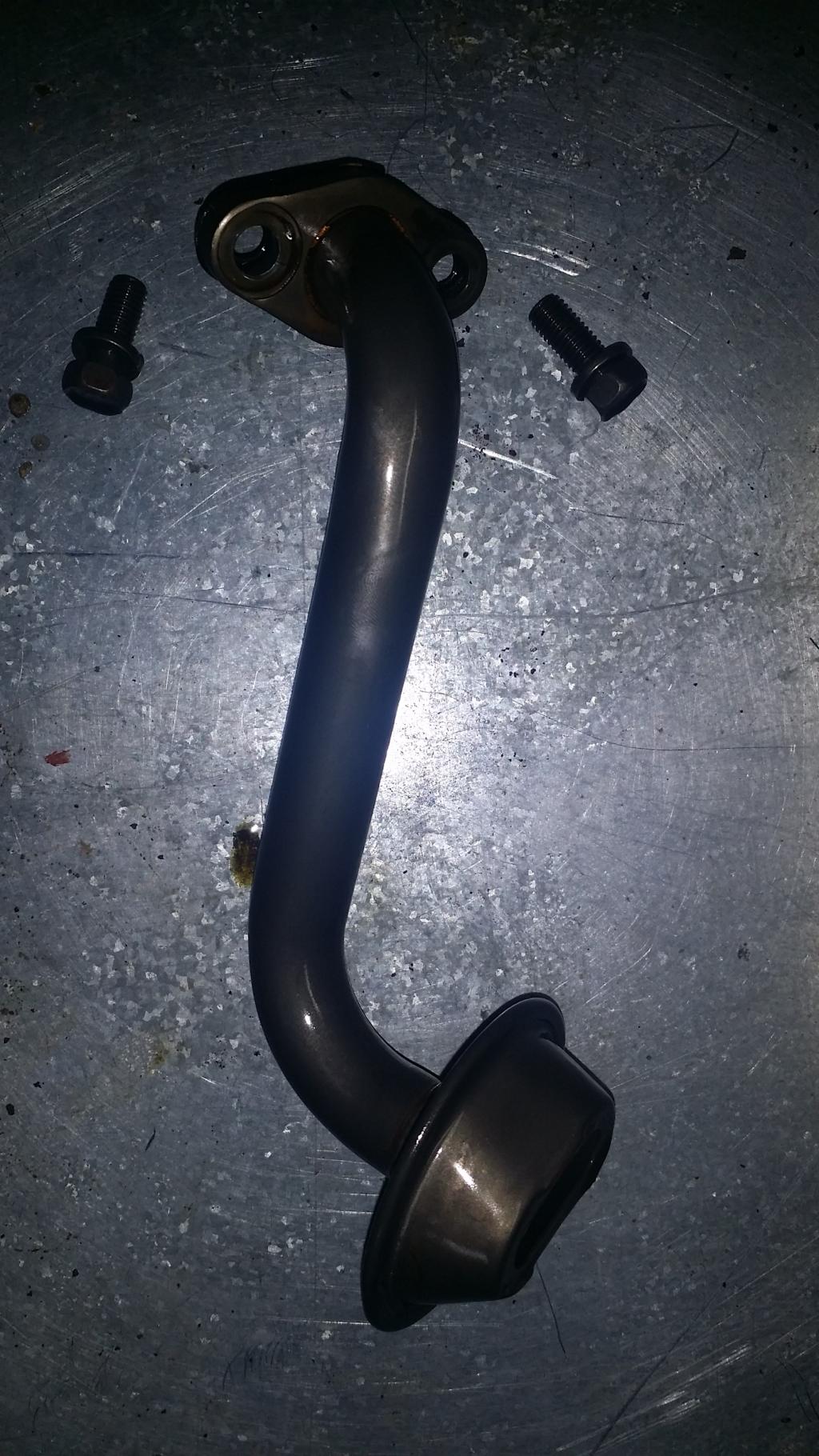
Now we are going to focus on the oil pickup. To get it off remove the two 12mm bolts holding it on. The gasket on this think was totally dead. It just started falling to pieces whenever I tried to take it off...
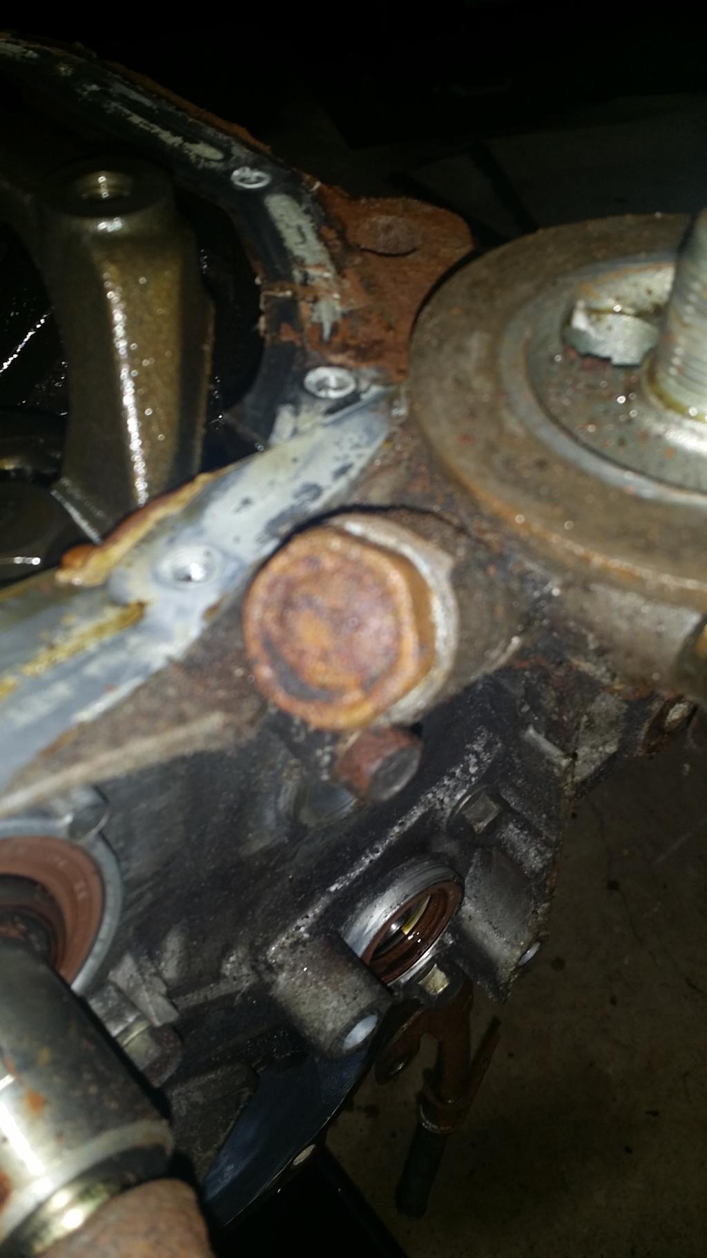
FSM now says we should remove the relief plug, spring, gasket, and plunger. However it doesnt appear mandatory to remove that so I'll just give you a picture of it for reference.
Now we can remove the oil filter bracket, also known as "the part the oil filter hangs off of". LOL! Now three 12mm bolts hold it on, the one nearest the oil filter is the long one.
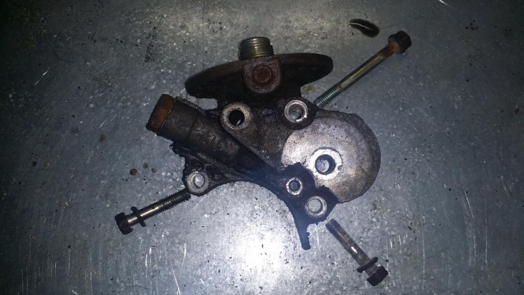
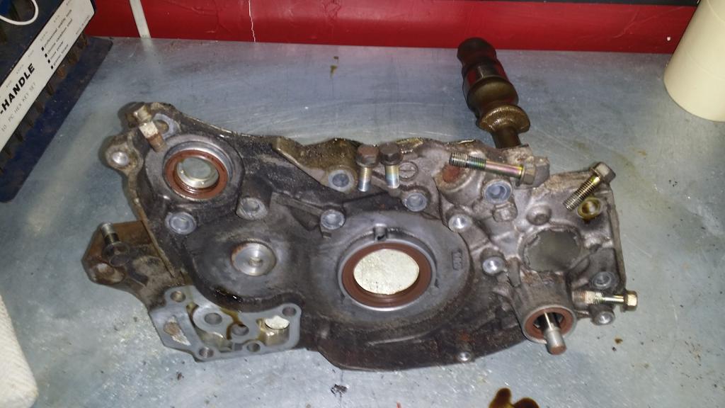
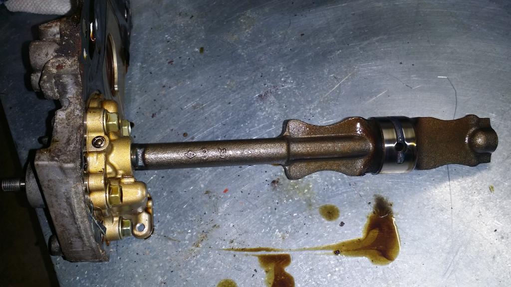
Now we are supposed to remove the "Plug", its o-ring, and a flange bolt. However it isnt necissary to remove the Front Case and I'll tackle that later when I delete the balance shafts. So lets focus on the front case. Hold it in place are seven 12mm bolts. Pull those and then GENTLY use a chisel to break the case loose from the block. I say gently because if your reusi ng the case you dont want to damage it since it is aluminum. Also keep in mind the bolts are of various lengths. I tried to place them in the picture near where they belong so you can see which are which.
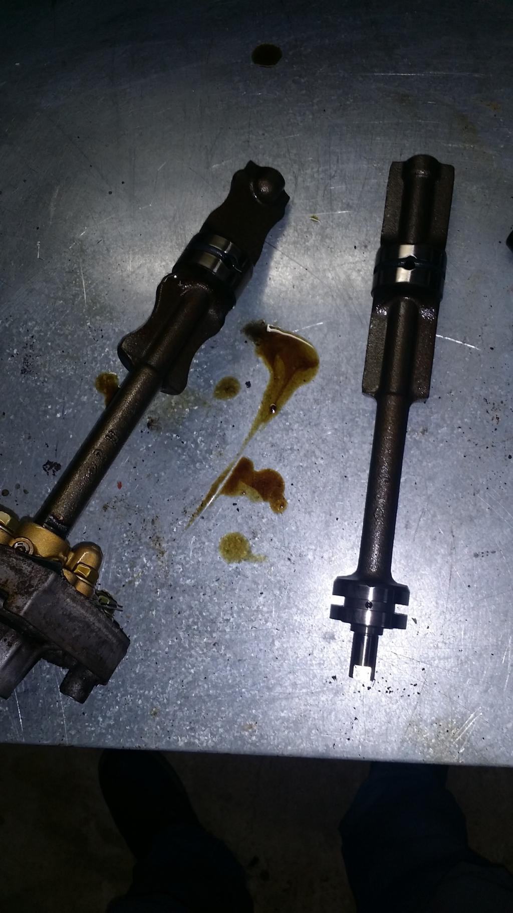
Now as you can see the non-oiled balance shaft came out with the case as it is geared in place with the oil pump unit, the oiled one is still chillin' inside the block. Gently pull it out so you dont damage anything. These things are surprisingly heavy for their size. And knowing the butt dyno difference between our stock crankshaft pulley and and the light weight one. Its easy to see how deleting these will free up some wasted horses, along with removing a potential failure point. Its also been said that the shafts, during prolonged track use, can cause the oil to froth up. IDK how true this is but Ive heard it enough times for it to somewhat make sense. Either way this puppies are gone!
================================================== ======================
Well that does it for all the chapters I had planned to write on the tear down. Sorry I didnt go into detail on the crankshaft, head, and things. But I was never planning to dive that far into it.
Im trusting the head work to an experienced performance shop, and from there I will begin the rebuild.
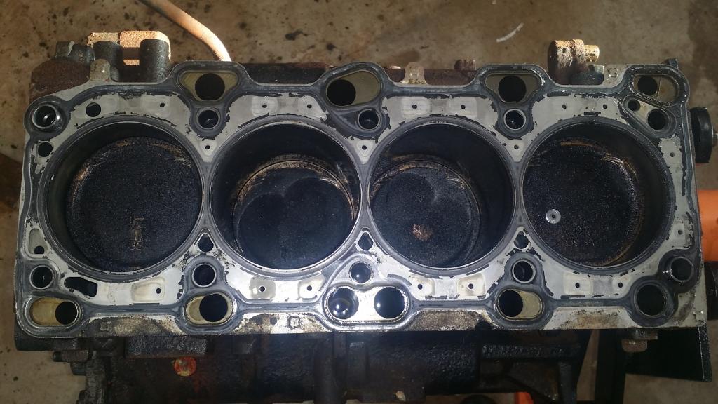
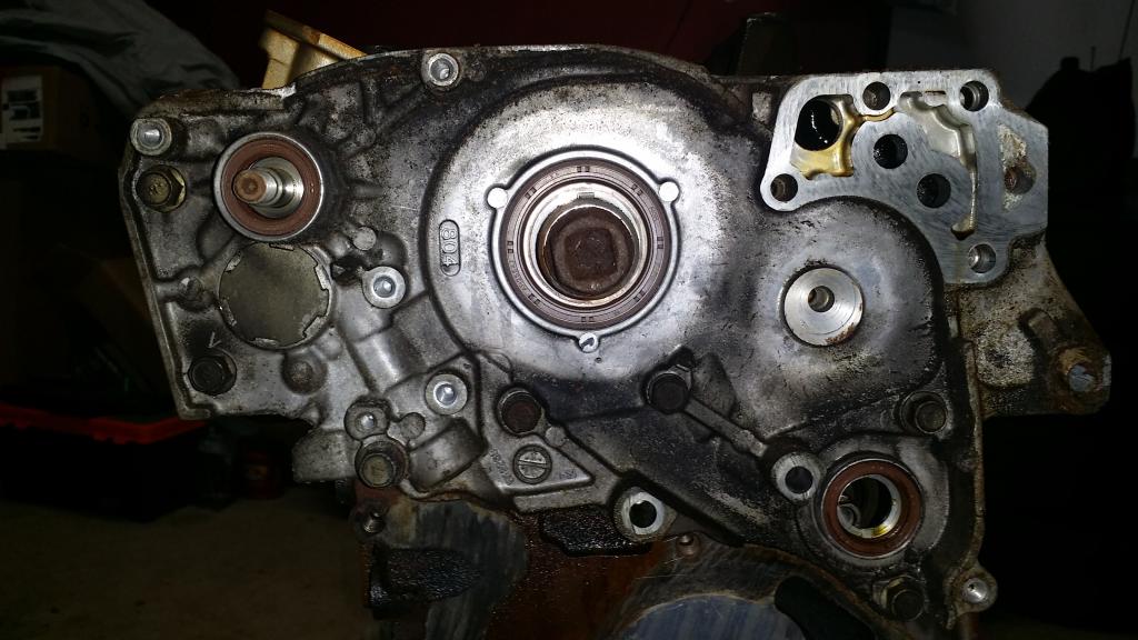
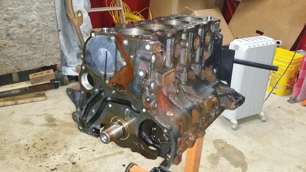
Here is a shot of the finished stripped down engine block
Here is my workbench. You can see all the parts we have removed are bagged and tagged, the 5-speed tranny, my work space for the write ups and reference material, my fuel for this tear down has been Angry Orchard Hard Cider, and they have been kept cool by the coolest koozie ever given to me from Nekkidlad!
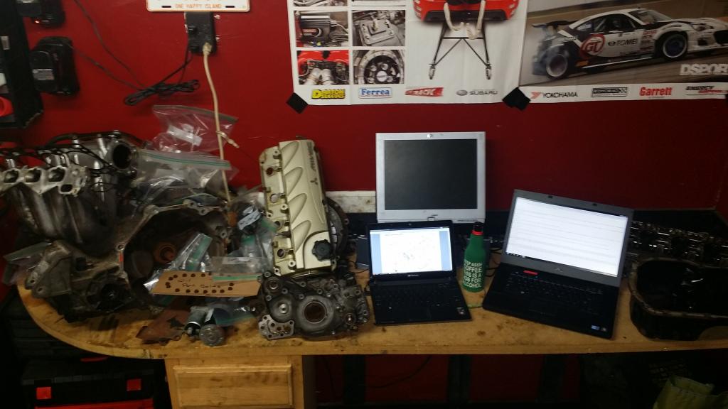
And finally in case you havent figured out what is in store for this engine here is a clue.

In closing I would like to say thank you to everyone for your positive comments and enthusiasm. Ive had a lot of fun documenting all of this for you all and it actually helped me to be more organized and think ahead before just ripping parts off. Thank you all once again I hope you have enjoyed following my mess.
-Josh
:// Oil Pan and Pump
Alright here we are. Everything is gone except for the oil system and the pistons and crankshaft. And since I am not planning to remove the crankshaft and pistons then this will be the last chapter of my disassembly.
If you would like for me to go back and give you more details on anything at this point them please ask and I will make a follow up Chapter to wrap everything up. I wouldnt mind to go back and get you bolt/nut sizes on the stuff I didnt disassemble if anyone is interested. I'll also go back and try to get screenshots from the FSM so that you all can see the diagrams of what all has been done. Plus I think they will be a handy reference to have on the site. As long as our mods are ok with it.
Anyway lets get into this. FSM says Drain plug and Gasket first, Im going to leave them in so I can set the pan on my work bench and it not leak oil. Next is the Oil filter which we removed a long time ago, and I hope you already know how to remove... lol! Item 4 is the oil pan. Now we can get started. To remove the pan you need to take out nineteen 10mm bolts from around the pan. Mine are obviously rusty so im going to take some time on them, hopefully none break.
To help me keep track of all the bolts and where they go since some of them are shorter than others. I found me a piece of cardboard and poked the bolts thru in the shape of the pan. That way when it goes back together there's no questioning what goes where.
Now the oil pan should be mated to the block using some RTV so it wont just lift off. I used a chisel and gently worked my way around until it was loose enough to lift off. Any idea what this pink stuff is?
And here we can see our crankshaft, con rods, underside of the pistons, and oil pickup.
Now we are going to focus on the oil pickup. To get it off remove the two 12mm bolts holding it on. The gasket on this think was totally dead. It just started falling to pieces whenever I tried to take it off...
FSM now says we should remove the relief plug, spring, gasket, and plunger. However it doesnt appear mandatory to remove that so I'll just give you a picture of it for reference.
Now we can remove the oil filter bracket, also known as "the part the oil filter hangs off of". LOL! Now three 12mm bolts hold it on, the one nearest the oil filter is the long one.
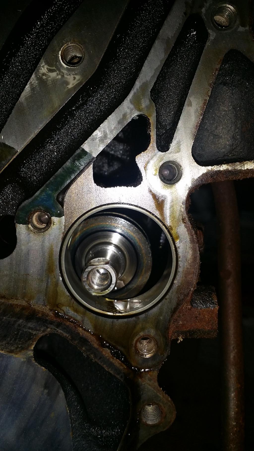
Now we are supposed to remove the "Plug", its o-ring, and a flange bolt. However it isnt necissary to remove the Front Case and I'll tackle that later when I delete the balance shafts. So lets focus on the front case. Hold it in place are seven 12mm bolts. Pull those and then GENTLY use a chisel to break the case loose from the block. I say gently because if your reusi ng the case you dont want to damage it since it is aluminum. Also keep in mind the bolts are of various lengths. I tried to place them in the picture near where they belong so you can see which are which.
Now as you can see the non-oiled balance shaft came out with the case as it is geared in place with the oil pump unit, the oiled one is still chillin' inside the block. Gently pull it out so you dont damage anything. These things are surprisingly heavy for their size. And knowing the butt dyno difference between our stock crankshaft pulley and and the light weight one. Its easy to see how deleting these will free up some wasted horses, along with removing a potential failure point. Its also been said that the shafts, during prolonged track use, can cause the oil to froth up. IDK how true this is but Ive heard it enough times for it to somewhat make sense. Either way this puppies are gone!
================================================== ======================
Well that does it for all the chapters I had planned to write on the tear down. Sorry I didnt go into detail on the crankshaft, head, and things. But I was never planning to dive that far into it.
Im trusting the head work to an experienced performance shop, and from there I will begin the rebuild.
Here is a shot of the finished stripped down engine block
Here is my workbench. You can see all the parts we have removed are bagged and tagged, the 5-speed tranny, my work space for the write ups and reference material, my fuel for this tear down has been Angry Orchard Hard Cider, and they have been kept cool by the coolest koozie ever given to me from Nekkidlad!
And finally in case you havent figured out what is in store for this engine here is a clue.
In closing I would like to say thank you to everyone for your positive comments and enthusiasm. Ive had a lot of fun documenting all of this for you all and it actually helped me to be more organized and think ahead before just ripping parts off. Thank you all once again I hope you have enjoyed following my mess.
-Josh
Last edited by bakuro117; Feb 11, 2015 at 08:37 PM.
Feb 11, 2015, 08:23 PM
#24
>: Questions and Answers :<
:// QnA Section
If you have any questions for me concerning this tear down, something I didnt cover well, specs, or just something you'd like to see a bit closer please ask. I made this as a QnA post which I will use to answer any questions I recieve, and have it linked to the opening post. This will of course only last until I start putting things back together so dont hold off on asking anything! I'll try to answer anything I can to the best of my ability. So ask away!
>: Question 1:
://
>: Question 2:
://
>: Question 3:
://
Feb 13, 2015, 05:57 AM
#28
lol yep. my thoughts exactly.
I was just down by VW yesterday. Went and checked out that Cylinder head place I tried to text you about. Dunno if you ever got it or not I still cant text... :/ I woulda swung by to say Hi but we were in a hurry to get home.
I was just down by VW yesterday. Went and checked out that Cylinder head place I tried to text you about. Dunno if you ever got it or not I still cant text... :/ I woulda swung by to say Hi but we were in a hurry to get home.
Feb 16, 2015, 08:23 AM
#29
Would like to thank you for creating this thread and taking the time to document each step of the dis-assembly. Over the weekend I took apart my 4G69 as well as I'm going to be doing a DOHC head swap with a built bottom end, and there were a few areas of your walkthrough that saved me some time (such as requiring the 12-point 12mm socket for the head studs).
I'm having a tough time getting the center crank bolt off. I've locked the flywheel side but this thing is insanely tight; I'm even using a 3 foot steel pipe extension placed over my socket wrench and I can't break it.
How might this special tool aid in getting this thing off; what exactly does this tool do?
Thanks again!