When you click on links to various merchants on this site and make a purchase, this can result in this site earning a commission. Affiliate programs and affiliations include, but are not limited to, the eBay Partner Network.
**First things first. I would like to thank Ant_Turbo for all the help with working some of the bugs out to make it easier on everyone when building this little project**
Things you’ll need
- Arduino Uno Here
- (optional) Arduino l2c LCD Screen Here
- 4.7k ohm resistor $1
- 3.3k ohm resistor $1
- USB Car Charger (5v 1amp) $1-$5
- Dorman 800-082 3/8” quick fuel connects
- Flex Fuel Sensor
**Library's needed to program the code** LCD library Drop these into your arduino library. make sure arduino is not open when you do!
Evoscan
Adding request 83 with (5/256)*(x) will display voltage giving the ability to have automatic map switching
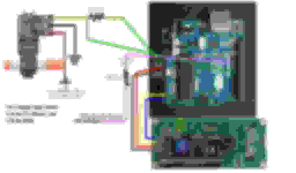
Wiring Credit to @ant_turbo for the pic! thanks!
Here is where i mounted my LCD. Had to trim slightly to get it to fit, but im very happy with it.
Code
/************************************************** *****
This program will sample a 50-150hz signal depending on ethanol
content, and output a 0-5V signal via PWM.
The LCD will display ethanol content, hz input, mv output, fuel temp
************************************************** ******/
// include the library code:
#include <Wire.h>
#include <LCD.h>
#include <LiquidCrystal_I2C.h>
int inpPin = 8; //define input pin to 8
int outPin = 11; //define PWM output, possible pins with LCD and 32khz freq. are 3 and 11 (UNO)
//Define global variables
volatile uint16_t revTick; //Ticks per revolution
uint16_t pwm_output = 0; //integer for storing PWM value (0-255 value)
int HZ; //unsigned 16bit integer for storing HZ input
int ethanol = 0; //Store ethanol percentage here
float expectedv; //store expected voltage here - range for typical GM sensors is usually 0.5-4.5v
uint16_t voltage = 0; //Store display millivoltage here (0-5000)
int duty; //Duty cycle (0.0-100.0)
float period; //Store period time here (eg.0.0025 s)
float temperature = 0; //Store fuel temperature here
int fahr = 0;
int cels = 0;
static long highTime = 0;
static long lowTime = 0;
static long tempPulse;
void setupTimer() // setup timer1
{
TCCR1A = 0; // normal mode
TCCR1B = 132; // (10000100) Falling edge trigger, Timer = CPU Clock/256, noise cancellation on
TCCR1C = 0; // normal mode
TIMSK1 = 33; // (00100001) Input capture and overflow interupts enabled
TCNT1 = 0; // start from 0
}
ISR(TIMER1_CAPT_vect) // PULSE DETECTED! (interrupt automatically triggered, not called by main program)
{
revTick = ICR1; // save duration of last revolution
TCNT1 = 0; // restart timer for next revolution
}
ISR(TIMER1_OVF_vect) // counter overflow/timeout
{ revTick = 0; } // Ticks per second = 0
void setup()
{
Serial.begin(9600);
pinMode(inpPin,INPUT);
setPwmFrequency(outPin,1); //Modify frequency on PWM output
setupTimer();
// set up the LCD's number of columns and rows:
lcd.begin(16, 2);
lcd.setBacklightPin(3,POSITIVE);
lcd.setBacklight(HIGH);
// Initial screen formatting
lcd.setCursor(1, 0);
lcd.print("Ethanol: %");
lcd.setCursor(0, 1);
lcd.print(" Hz F");
}
if (revTick > 0) // Avoid dividing by zero, sample in the HZ
{HZ = 62200 / revTick;} // 3456000ticks per minute, 57600 per second
else
{HZ = 0;} //needs real sensor test to determine correct tickrate
//calculate ethanol percentage
if (HZ > 50) // Avoid dividing by zero
{ethanol = (HZ-50);}
else
{ethanol = 0;}
if (ethanol > 99) // Avoid overflow in PWM
{ethanol = 99;}
expectedv = ((((HZ-50.0)*0.01)*4)+0.5);
//Screen calculations
pwm_output = 1.11 * (255 * (expectedv/5.0)); //calculate output PWM for NEMU
lcd.setCursor(12, 0);
lcd.print(ethanol);
lcd.setCursor(2, 1);
lcd.print(HZ);
lcd.setCursor(12, 1);
lcd.print(fahr); //Use this for celsius
//PWM output
analogWrite(outPin, pwm_output); //write the PWM value to output pin
delay(1000); //make screen more easily readable by not updating it too often
tempPulse = pulseIn(inpPin, LOW, 25000); // Measure the low pulse time (timeout after 25ms if no pulse is detected)
if (tempPulse > 0) { // If we get a pulse then update the temperature measurement
lowTime = tempPulse;
float celsius = ((41.25 * (float(lowTime) / 1000)) - 81.25); // Calculate temp in celsius from lowTime pulse
float fahrenheit = ((celsius * 1.8) + 32); // Convert to fahrenheit
temperature = fahrenheit; // Update temperature with specified unit
}
}
duty = ((100*(highTime/(double (lowTime+highTime))))); //Calculate duty cycle (integer extra decimal)
float T = (float(1.0/float(HZ))); //Calculate total period time
float period = float(100-duty)*T; //Calculate the active period time (100-duty)*T
float temp2 = float(10) * float(period); //Convert ms to whole number
temperature = ((40.25 * temp2)-81.25); //Calculate temperature for display (1ms = -40, 5ms = 80)
int cels = int(temperature);
cels = cels*0.1;
float fahrtemp = ((temperature*1.8)+32);
fahr = fahrtemp*0.1;
}
void setPwmFrequency(int pin, int divisor) { //This code snippet raises the timers linked to the PWM outputs
byte mode; //This way the PWM frequency can be raised or lowered. Prescaler of 1 sets PWM output to 32KHz (pin 3, 11)
if(pin == 5 || pin == 6 || pin == 9 || pin == 10) {
switch(divisor) {
case 1: mode = 0x01; break;
case 8: mode = 0x02; break;
case 64: mode = 0x03; break;
case 256: mode = 0x04; break;
case 1024: mode = 0x05; break;
default: return;
}
if(pin == 5 || pin == 6) {
TCCR0B = TCCR0B & 0b11111000 | mode;
} else {
TCCR1B = TCCR1B & 0b11111000 | mode;
}
} else if(pin == 3 || pin == 11) {
switch(divisor) {
case 1: mode = 0x01; break;
case 8: mode = 0x02; break;
case 32: mode = 0x03; break;
case 64: mode = 0x04; break;
case 128: mode = 0x05; break;
case 256: mode = 0x06; break;
case 1024: mode = 0x7; break;
default: return;
}
TCCR2B = TCCR2B & 0b11111000 | mode;
}
}
I have modified my own code for a lcd screen output. If you would like the code to have a 16x2 display, please let me know.
Originally Posted by ant_turbo
Ok tested and working 100% thanks,, mrb00st,, My problem was 1st I had the wrong libraries,, NOTE,,, My second problem was when testing and plugged in the laptop via USB to power the ARDUINO up u have to ground the arduino I DID NO KNOW THAT,,, I had it all set up on in my garage and hooked up to my spare car battery and set the FF sensor in a small container of E85 and some E85/98 MIX just to make sure it was working properly
So remember to ground the arduino when testing with the laptop via the USB.
To do that all I did was used my circuit tester clipped to the battery negative and just touched the metal top part where the USB plugs into the arduino,,
To test and make sure everything is running and your getting the correct readings or if you have to LCD hooked up to the arduino,, When you have everything hooked up open the arduino software and go to tools then serial monitor and a window will pop up and it will start to show readings,, it will show 4 readings ,
In order and keep repeating,,
1.pulse width modulated
2.Voltage
3.Hz
4.E85 content
VIDEO LINK https://www.youtube.com/watch?v=DKKIKcE7abw
That's friggin sweet, well done! Might have to give this a shot at some point. But of course until I go with a true flex fuel setup Im still testing my fuel prior. Still a slick gauge love the DIY aspect and the cleanliness of it all.
Wow I have been looking into doing my own content display recently and I'm glad that I stumbled upon this post. Thanks a lot I will be looking into this once I go FF with my aem infinity. Is that flex fuel sensor that you have linked on amazon the same one/place that you purchased yours?