
JDMMAP vs ZT-2 MAP

All this talk about sensor placement makes me nervous.....
I have an analog boost gauge, and EBC with boost gauge, and the SMC kit with MAP sensor all T'd off one line coming from the intake manifold. As far as I can tell all three are dead on with one another but I have no idea if that is what the motor is actually seeing.
I have an analog boost gauge, and EBC with boost gauge, and the SMC kit with MAP sensor all T'd off one line coming from the intake manifold. As far as I can tell all three are dead on with one another but I have no idea if that is what the motor is actually seeing.


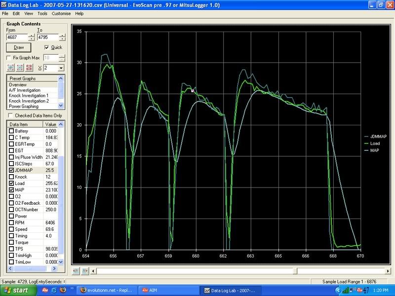
I can't log over 25psi on the zt-2 map sensor in mitsulogger until MJ releases the next version. Peak boost was 31.7 according to the peak hold function of the zt.2. I max'd the jdm sensor out at 33psi. The curves are a little closer and I personally think the discrepancy is due to sensor placement.
I really think this might be a case of ECU lag like NJ is saying. I do however find it odd if it is lag, that it would cause a 7psi difference. Maybe the JDM map sensor is just really sensitive to high PSI and spikes in its readings?
Are you falling into 31psi load columns that the JDM map is saying or 24.4 psi load columns like the ZT-2 is saying?
I'll try to install my JDM sensor this week and get some logs as well.
EvoM Guru
iTrader: (50)
Joined: Mar 2006
Posts: 9,675
Likes: 132
From: Tri-Cities, WA // Portland, OR
The thing is that with mmm's logs, the ZT-2 response is lagging far behind the JDM sensor by a significant margin. Its the opposite of what nj is saying.

This talk about sensor response time is confusing me. MrFred is saying that the non-JDM sensor is lagging in response, NJ is saying that the JDM sensor is the laggard. I'm not sure either one is "lagging," necessarily.
This may have something to do with the sample location. Are we sure that the MAP sensor location on the intake mani is ideal for sampling 24psi of boost? After all, Mitsu designed this port so that the stock sensor could read a very small amount of pressure to ensure that the EGR system was functioning. Could the little pocket in there be causing turbulence contaminating the reading?
Could the sensor become less accurate at boost levels above "2x"psi? (ie, this could be a sensor deficiency or a sample location problem). The empirical data seems to suggest that the sensor logs lower boost (and idle vacuum) activity properly, but wanders a bit "off the range" in high boost scenarios.
On the other hand, could this be *the* ideal place/sensor to sample boost, making all of our other readings obsolete as they are lagging by being farther from the source?
Last edited by Pd1; May 29, 2007 at 10:18 AM.


Thread Starter
Account Disabled
iTrader: (1)
Joined: Jun 2006
Posts: 472
Likes: 0
From: Taftville, CT
Here's load graphed with the map data. Keep in mind, my load is atypical due to the maft-pro with the GM MAF sensor. The JDM sensor seems to be tracking perfectly with load, though. Load is 2byte load.
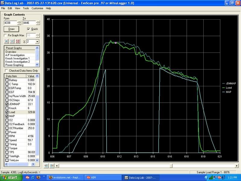
Now that is very interesting. I also just noticed you have 12 counts of knock in the first graph and 6 counts in the 2nd graph.
Maybe you really are boosting that much. :-X What does your AVC-R say?
Anyway you can lower boost to say 20-22psi and see if they match closer?
Maybe you really are boosting that much. :-X What does your AVC-R say?
Anyway you can lower boost to say 20-22psi and see if they match closer?

before i got this sensor installed and logged boost, i was oveboosting at spikes around 26 and 25psi on 91 octane, i have since lowered the boost to near 21. Hope you get this sensor stuff worked out.

What I suspect I will find is that the sampling rate on the LMA-2/LM-1 is faster than the sampling rate from the ECU port. That does not mean that one is more accurate than the other. It does mean that one has more samples than the other. What I have noticed when logging rpm with the LMA-2/LM-1 and the ECU port is that the former hits 7500 rpm ahead of the latter. The ECU is simply slower.
This may have something to do with the sample location. Are we sure that the MAP sensor location on the intake mani is ideal for sampling 24psi of boost? After all, Mitsu designed this port so that the stock sensor could read a very small amount of pressure to ensure that the EGR system was functioning. Could the little pocket in there be causing turbulence contaminating the reading?
Thread Starter
Account Disabled
iTrader: (1)
Joined: Jun 2006
Posts: 472
Likes: 0
From: Taftville, CT
Now that is very interesting. I also just noticed you have 12 counts of knock in the first graph and 6 counts in the 2nd graph.
Maybe you really are boosting that much. :-X What does your AVC-R say?
Anyway you can lower boost to say 20-22psi and see if they match closer?
Maybe you really are boosting that much. :-X What does your AVC-R say?
Anyway you can lower boost to say 20-22psi and see if they match closer?
I haven't really looked at what the AVC-R is showing for peak boost. I only used the ZT-2 for that. I just set the AVC-R until the ZT-2 showed what I wanted it to. I'll get some more data on my way into work tonight, with the AVC-R off (wastegate pressure) and with it set to 22 psi.
I will be logging the JDM MAP sensor from two locations, via the ECU port and via the LMA-2/LM-1. I hope to do it today if the humidity level where I am falls down. Right now I cannot even see the sun. It is very cloudy and humid.
What I suspect I will find is that the sampling rate on the LMA-2/LM-1 is faster than the sampling rate from the ECU port. That does not mean that one is more accurate than the other. It does mean that one has more samples than the other. What I have noticed when logging rpm with the LMA-2/LM-1 and the ECU port is that the former hits 7500 rpm ahead of the latter. The ECU is simply slower.
I do not think that is the problem. I have logged the JDM MSP sensor on my bone stock 9 and got 19.7 psi peak. Mitsu tells us that the 9 peak is 20.3 psi. That is very close and I suspect I could have hit 20.3 psi had it not been to the 60% humidity during testing.
Moreover, logging a stock IX at around 20psi doesn't say anything other than that the JDM MAP is probably accurate up to that boost level. We're specifically trying to figure out why these sensors "log" 30+psi when the expected boost level is really around 24psi. Your 19.7psi log doesn't justify the statement of "I do not think that is the problem."
Thread Starter
Account Disabled
iTrader: (1)
Joined: Jun 2006
Posts: 472
Likes: 0
From: Taftville, CT
If the ECU were slower, then the ZT-2 map would be showing peak boost and decay before the JDM map. My logs show it the other way around. I think its due to the sensor location.

But if your load calc is really 330 as that log says, holy crap batman somethings going
on
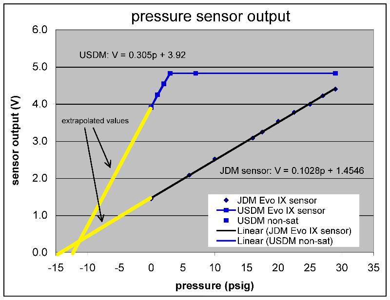
I logged the JDM MAP sensor using two methods. The first method was logging from the ECU port. The second method bypassed the port and logged from the wire that sends the voltage to the ECU. It is the solid yellow wire on ECU C-plug pin #92. I took the voltage from that pin and fed it into the LMA-2 and then to the LM-1 and logged it into the computer. Then I used the following volt-to-psi conversion based on mrfred's calculations
PSI----Volt
-14.7---0
-8.9-----0.593
-4.4----1.056
0-------1.508
20.1---3.574
32.7---4.870
I did 4 logs and found that the second method gave higher boost than the first method. The difference is not huge, it is about 0.7-0.8 psi difference between the two. The table below shows the second method (PSI Chart) on top and the first method (Jdm_boost Chart) on the bottom.
Overall I noticed that both trace lines track very well together. The LMA-2/LM-1 boost trace was more spikey while the ECU Port trace was more steppy and lagged slightly behind the LMA-2/LM-1 trace.
Last edited by nj1266; May 29, 2007 at 04:31 PM.
EvoM Guru
iTrader: (50)
Joined: Mar 2006
Posts: 9,675
Likes: 132
From: Tri-Cities, WA // Portland, OR
I just want to mention in this thread that I have measured the response of the JDM MAP sensor to 30+ psi on a bench top using lab quality pressure gauges, a high quality volt meter, and a nice 5V power source. I set up a manifold and measured the output of the JDM MAP sensor versus applied pressure. In these static test conditions, the output was perfectly linear with applied pressure.
That doesn't rule out some non-linearity under transient high boost conditions, but I think there is enough evidence to suggest otherwise. The range of boost in question seems to be in the 23-30 psi range. With my car, I see 23-25 psi from my JDM MAP sensor, and this matches the output of my MR boost gauge which I also checked on the same bench top manifold. There is another guy who is peaking at 27 psi, and he says that the JDM MAP sensor is exactly matching his aftermarket boost gauge. I know of other people who are seeing good agreement between the JDM MAP sensor and other boost meters in the 23-25 psi range.
That doesn't rule out some non-linearity under transient high boost conditions, but I think there is enough evidence to suggest otherwise. The range of boost in question seems to be in the 23-30 psi range. With my car, I see 23-25 psi from my JDM MAP sensor, and this matches the output of my MR boost gauge which I also checked on the same bench top manifold. There is another guy who is peaking at 27 psi, and he says that the JDM MAP sensor is exactly matching his aftermarket boost gauge. I know of other people who are seeing good agreement between the JDM MAP sensor and other boost meters in the 23-25 psi range.