
LC-1 installed, logging AFR without serial cable

Thread Starter
EvoM Guru
iTrader: (50)
Joined: Mar 2006
Posts: 9,675
Likes: 132
From: Tri-Cities, WA // Portland, OR
LC-1 installed, logging AFR without serial cable
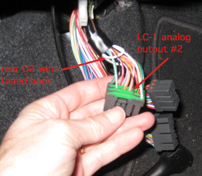
I finally got around to installing my LC-1 this weekend. I didn't want the hassle of attaching both the OpenPort cable and a serial cable every time I logged data, so I decided to route the LC-1 signal into the ECU, and read the LC-1 AFR data from the ECU. First step was to apply my rear O2 sim patch (and make a few other minor ROM changes). This freed up the rear O2 ADC input to be used for reading the analog output 2 wire from the LC-1. Next step was to pull the rear O2 signal wire from the ECU plug and install the LC-1 analog output #2 wire into the ECU plug. This part was kinda of a PITA because I only had Evo 8 pins, and they do not fit into the Evo 9 plug without some grinding and hacking on the pin. (Jack_of_Trades will have 7000 Evo 9 pins in a month or two.) Anyhow, I got it in there (see pic below), and finished up the LC-1 install. I've only had a chance to start the car for a few seconds, but it was enough to verify that this setup works perfectly.
If anyone would like to setup their LC-1 this way, I can write something more descriptive.
If anyone would like to setup their LC-1 this way, I can write something more descriptive.

Great, the same day I spend 42 dollars on an adapter that flies around my floor you post this!
I finally got around to installing my LC-1 this weekend. I didn't want the hassle of attaching both the OpenPort cable and a serial cable every time I logged data, so I decided to route the LC-1 signal into the ECU, and read the LC-1 AFR data from the ECU. First step was to apply my rear O2 sim patch (and make a few other minor ROM changes). This freed up the rear O2 ADC input to be used for reading the analog output 2 wire from the LC-1. Next step was to pull the rear O2 signal wire from the ECU plug and install the LC-1 analog output #2 wire into the ECU plug. This part was kinda of a PITA because I only had Evo 8 pins, and they do not fit into the Evo 9 plug without some grinding and hacking on the pin. (Jack_of_Trades will have 7000 Evo 9 pins in a month or two.) Anyhow, I got it in there (see pic below), and finished up the LC-1 install. I've only had a chance to start the car for a few seconds, but it was enough to verify that this setup works perfectly.
If anyone would like to setup their LC-1 this way, I can write something more descriptive.
If anyone would like to setup their LC-1 this way, I can write something more descriptive.


yay someone finally bothered to do it 
few questions:
1) what voltage does the ADC accept, narrow band is 0-1v, so is that pulled down someplace in the ECU or before hand?
2) you only had to connect the signal wire? ie the ground wire (isn't one) works via the chassis?
3) is the logging via analogue faster than serial?
4) what AFR range have you configured in your LC1, I'm thinking 10(0v)-17.0(1v), then use 13.5 as .5v, should make the formula for Evoscan easy
Evolving Member
Joined: Apr 2007
Posts: 195
Likes: 1
From: Slovakia
regarding the logging speed - I am using similar setup except that I am not using the rear 02 input but a free one which is on the EDM Evo 8 - when I was comparing serial signal and the signal going through ECU - both in Evoscan - then the serial was sligtly behing the ECU. So serial has some kind of a smal delays against the data going through ECU.

please do write up something more descriptive.
I have my LC1 in the box waiting to be installed,
and a spare ADC as my rom dont need the rear o2 sensor,
so please share the wealth,
cheers
I have my LC1 in the box waiting to be installed,
and a spare ADC as my rom dont need the rear o2 sensor,
so please share the wealth,
cheers
Trending Topics
Evolving Member
Joined: Apr 2007
Posts: 195
Likes: 1
From: Slovakia
Barry - no problem (I have been posting this on aktivematrix last year - but simply:
5v analog output is connected to PIN 74 on the ecu - request id is MUT88. Formula in evoscan is 7.1731+0.08847*x - the reason for this formula is that even with the output of LC-1 set constantly to 5v (in the setup menu) - the raw value shown is only 174 (instead of expected 255) so I had to calculate and interpolate.
12v I am taking from the switched 12v supply that is feeding ECU (pin 25). Grounds are taken from the chassis ground bolt which is close to the ECU.
Speaking as a DSMLink user, I wholeheartedly like. 
Tephra, at least on 2g DSM ECUs, the rear O2 can handle a 0-5V input (w/a 220k pull down), and I'd be surprised to see that change on an Evo. There's more info on the DSMLink wiki here and here.
As for grounding the analog output, I could have sworn the analog ground was supposed to run to the same location as everything else on the LC1, but I'd need to recheck the documentation to be sure.
I'm curious what those "other minor ROM changes" might have been.
What's more interesting to me than running the wideband to the ECU in this particular case (because most of us can log our widebands in other ways) is the fact that this opens up a 5V input for just about anything. And, there's a few sources we can borrow calculation formulas from. And since the two "big" sensors (wideband and boost) are already easily handled on our cars, that leaves the rear O2 input available for more exotic stuff (fuel pressure is one I'm particularly interested in).
Tephra, at least on 2g DSM ECUs, the rear O2 can handle a 0-5V input (w/a 220k pull down), and I'd be surprised to see that change on an Evo. There's more info on the DSMLink wiki here and here.
As for grounding the analog output, I could have sworn the analog ground was supposed to run to the same location as everything else on the LC1, but I'd need to recheck the documentation to be sure.
I'm curious what those "other minor ROM changes" might have been.
What's more interesting to me than running the wideband to the ECU in this particular case (because most of us can log our widebands in other ways) is the fact that this opens up a 5V input for just about anything. And, there's a few sources we can borrow calculation formulas from.
And since the two "big" sensors (wideband and boost) are already easily handled on our cars, that leaves the rear O2 input available for more exotic stuff (fuel pressure is one I'm particularly interested in).
good stuff
so seems like any wideband o2 signal should work
x2 on the write up
hey evo828 I thought the rear o2 sensor pin was 75?
so seems like any wideband o2 signal should work
x2 on the write up
hey evo828 I thought the rear o2 sensor pin was 75?
Last edited by bnice01; Apr 7, 2008 at 06:42 AM.
It would be nice, if we could replace the whole rear o2 with a wideband sensor.
VW o2 sensors are wideband o2's, Bosch Part # 17014 (this is the same o2 sensor in my turboxs wideband)
http://www.musclecarclub.com/carpart..._Oxygen_Sensor
wiring diagram:
Red = Heater +
White = Heater -
Black = Signal wire
Gray = signal gnd
Yellow = pump circuit (that adds or removes oxygen from the o2) corrects things.
If you want you can find a cheap wideband gauge to wiring it up to sensor, if you like looking @ #'s all day LOL
http://www.dynotunenitrous.com/store...?idproduct=171
Last edited by bnice01; Apr 7, 2008 at 06:58 AM.
Evolving Member
Joined: Apr 2007
Posts: 195
Likes: 1
From: Slovakia
The setup that mrfred is doing is using the rear O2 input of the ECU (ie pin 75 on evo8 but not sure about the evo9 input pin).
The setup that I am running is using a FREE input on a evo8 ecu (which is pin 74 for example on european spec). However - you need to check whether it is free on your as well.
The setup that I am running is using a FREE input on a evo8 ecu (which is pin 74 for example on european spec). However - you need to check whether it is free on your as well.