


Evo8 ECU in a 1G DSM in the works!


5. Looking at the EVO ignition system, I don't see where it has any tach output anywhere, other than pin #58 of the ECU, which I think is just a testpoint for technicians to clip on to to read the rpm's. The 1G only uses the tach signal to check for misfires anyway, so the EVO ECU must use a different system, like the P030X Random Misfire stuff perhaps. So, I would just suggest leaving pin #58 unconnected, as you have.
Edit: Just checked the diagram for 2gs and we do in fact leave 58 disconnected.
Last edited by the_mork; Jan 8, 2010 at 06:24 AM.

Jeff, I went through the VIII service manual a while back and compared pinouts against a couple of online resources (most of which are based on RRE's old pinout). I found a few mistakes, some of which I suspect RRE added to identify people who ripped off their pinout diagram.
Anyway, I documented what I found on the wiki, if you want to take a peek. Updates are more than welcome.
Anyway, I documented what I found on the wiki, if you want to take a peek. Updates are more than welcome.

It is definitely worth a try. I believe the MSD has its own tach output, right? You only need the adapter when you are trying to connect both the dash tach and 1990 ECU at the same time, would be my guess. The 1990 "tach driver" module on the coilpack puts out +12 volt or so pulses for the tach signal. The MSD box and 1991+ DSM's have GROUND pulses instead for the tach signal, which doesn't play well with the 1990 ECU. The circuitry inside the 1990 ECU screws with the ground pulses, and makes the 1990 dash tach swing around wildly. But, without the 1990 ECU in the circuit the dash tach might actually work fine. Just connect pin #58 of the EVO ECU to pin #109 of the 1G ECU harness. It *should* backfeed the tach pulses to the dash tach, if the wiring behind the dash is still intact. Just be sure to disconnect the tach wire under the hood from everything, including the MSD tach driver module.
Jeff, I went through the VIII service manual a while back and compared pinouts against a couple of online resources (most of which are based on RRE's old pinout). I found a few mistakes, some of which I suspect RRE added to identify people who ripped off their pinout diagram.
Anyway, I documented what I found on the wiki, if you want to take a peek. Updates are more than welcome.
Anyway, I documented what I found on the wiki, if you want to take a peek. Updates are more than welcome.
I finished the EVO-to-1G harness tonight. It was actually easier than the 2G-to-1G harness, as the EVO ECU has less in common with a 1G.
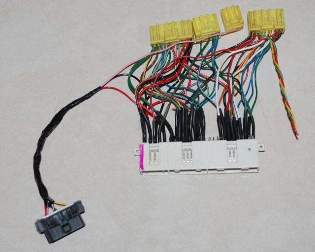
Now I just need to find an EVO8 ECU and get the xml and ROM image from someone, which is going to be tough because I don't have the 50 posts yet that are necessary for the For Sale area.




Ok, I think people have a good idea of how to make the harness. Now lets get everything in the car in a clean manner. I would REALLY suggest that anybody doing this do the speed density from the get go, unless they want to run a MAS for some reason.
After wiring you should have something like this:
IMG_0084.jpg?t=1263052118
To make SD easier you can buy a conversion harness from: http://www.fullthrottlespeed.com/ite...asp?ic=050SD1G
English Racing sells and has good access to the Omni 4 bar in a GM form factor shown below. The GM IAT is also used, ER should be able to source them if not they are easy to find. Plug everything in.
 000_1391.jpg?t=1263052188
Next you need to get your GM BCS to plug into the factory harness. It turns out that a current limiting resistor is no longer needed. Thus you have to source a male plug to plug into the factory BCS connection and wire that into the GM BCS plug. These plugs are found all over a DSM so if you don't have any just make a trip to the junkyard. I have found them in the HVAC airbox, low level coolant switch, just all over the car.

Last, you want to get that ecu securely into the car. What I do is take the base from the bad ecu that you procured and bend the 4 tabs out a little bit. You can then slip the ecu body into this. Use some shoo-goo or hot glue on the tabs to the ecu, this will keep the ecu locked in. You can now bolt the ecu into the car like factory.

After wiring you should have something like this:
IMG_0084.jpg?t=1263052118

To make SD easier you can buy a conversion harness from: http://www.fullthrottlespeed.com/ite...asp?ic=050SD1G
English Racing sells and has good access to the Omni 4 bar in a GM form factor shown below. The GM IAT is also used, ER should be able to source them if not they are easy to find. Plug everything in.
000_1391.jpg?t=1263052188
Next you need to get your GM BCS to plug into the factory harness. It turns out that a current limiting resistor is no longer needed. Thus you have to source a male plug to plug into the factory BCS connection and wire that into the GM BCS plug. These plugs are found all over a DSM so if you don't have any just make a trip to the junkyard. I have found them in the HVAC airbox, low level coolant switch, just all over the car.
Last, you want to get that ecu securely into the car. What I do is take the base from the bad ecu that you procured and bend the 4 tabs out a little bit. You can then slip the ecu body into this. Use some shoo-goo or hot glue on the tabs to the ecu, this will keep the ecu locked in. You can now bolt the ecu into the car like factory.
Last edited by 0xDEAD; Jan 9, 2010 at 08:05 AM.
You are running the GM BCS off of the wastegate harness connector under the hood, right? I passed pin 11 of the EVO ECU thru to pin #105 just for that purpose.
I soldered a 2.2k pullup resistor between pins 104 and 110 of the 1G connector, to use the upper cruise control switch for NLTS. Sound right? I guess if the customer wants to retain cruise control they will just have to cut the wire off and the clutch cutout just won't function.
For the MAP sensor you are just using a flying lead from pin #73, right? And the IAT is a flying lead from pin #77? Or, are you using the MAS connector under the hood for your MAP and IAT sensors? There seems to be 2 different camps/opinions on adding speed density here. Using pins 73 and 77 would allow an easier migration to speed density later, IMHO.
One final question: does the EVO/2G knock sensor use a different style plug than a 1G? What is the best way to make this work cleanly if so?
I soldered a 2.2k pullup resistor between pins 104 and 110 of the 1G connector, to use the upper cruise control switch for NLTS. Sound right? I guess if the customer wants to retain cruise control they will just have to cut the wire off and the clutch cutout just won't function.
For the MAP sensor you are just using a flying lead from pin #73, right? And the IAT is a flying lead from pin #77? Or, are you using the MAS connector under the hood for your MAP and IAT sensors? There seems to be 2 different camps/opinions on adding speed density here. Using pins 73 and 77 would allow an easier migration to speed density later, IMHO.
One final question: does the EVO/2G knock sensor use a different style plug than a 1G? What is the best way to make this work cleanly if so?

Newbie
Joined: Sep 2005
Posts: 43
Likes: 0
From: Haverhill, MA
You are running the GM BCS off of the wastegate harness connector under the hood, right? I passed pin 11 of the EVO ECU thru to pin #105 just for that purpose.
I soldered a 2.2k pullup resistor between pins 104 and 110 of the 1G connector, to use the upper cruise control switch for NLTS. Sound right? I guess if the customer wants to retain cruise control they will just have to cut the wire off and the clutch cutout just won't function.
For the MAP sensor you are just using a flying lead from pin #73, right? And the IAT is a flying lead from pin #77? Or, are you using the MAS connector under the hood for your MAP and IAT sensors? There seems to be 2 different camps/opinions on adding speed density here. Using pins 73 and 77 would allow an easier migration to speed density later, IMHO.
One final question: does the EVO/2G knock sensor use a different style plug than a 1G? What is the best way to make this work cleanly if so?
I soldered a 2.2k pullup resistor between pins 104 and 110 of the 1G connector, to use the upper cruise control switch for NLTS. Sound right? I guess if the customer wants to retain cruise control they will just have to cut the wire off and the clutch cutout just won't function.
For the MAP sensor you are just using a flying lead from pin #73, right? And the IAT is a flying lead from pin #77? Or, are you using the MAS connector under the hood for your MAP and IAT sensors? There seems to be 2 different camps/opinions on adding speed density here. Using pins 73 and 77 would allow an easier migration to speed density later, IMHO.
One final question: does the EVO/2G knock sensor use a different style plug than a 1G? What is the best way to make this work cleanly if so?
73 -> 16
77 -> 8
and using the MAFT Pro harness as Dan suggested. I may put terminals on the Evo Baro and IAT pins to allow an easy switch back to using a MAS if needed.
Evo 8/9 knock sensor plugs directly into the 1g harness.
The pull-up should work, just make sure that pin 104 isn't passing through to the factory harness as it'll ground out. The other option is just to wire the clutch swictch to the factory pin 104 which keeps it grounded at all times. The car will have a 2 step until it goes above the MPH you set in the rom. However the NLTS will not work and should not be enabled in the tephra mods.
Correct, I am running the GM BCS from the factory connection in the engine bay.
You can switch the IAT input when setting up the speed density to keep it on the IAT input of the ecu. I didn't do that as I forgot that I could. I will change my harnesses over when I get time. Then I will only have to switch the baro input to go back to a MAF if need be.
The pull-up should work, just make sure that pin 104 isn't passing through to the factory harness as it'll ground out. The other option is just to wire the clutch swictch to the factory pin 104 which keeps it grounded at all times. The car will have a 2 step until it goes above the MPH you set in the rom. However the NLTS will not work and should not be enabled in the tephra mods.
Correct, I am running the GM BCS from the factory connection in the engine bay.
You can switch the IAT input when setting up the speed density to keep it on the IAT input of the ecu. I didn't do that as I forgot that I could. I will change my harnesses over when I get time. Then I will only have to switch the baro input to go back to a MAF if need be.
All, I may be wrong about the clutch input needing a pullup. If you look at the FSM page 90-40 in CIRCUIT DIAGRAMS you will see that the clutch input pulls pin 43 to ground. I think the ECU may provide the 12 pull-up internally. I don't have a car here to test this at the moment. When I asked someone to test this I just asked what the voltage at pin 43 was with the clutch up and the clutch down. I assumed a pull-up was external to the ecu, which it may or may not be. Either way, it shouldn't damage anything, but it would simplify the wiring.
Yep, you're right; I must have been in a hurry when I was copying that from the service manual. Thanks for the catch, I'll update the website.
We have the GM style 4 bar and IATs in stock ready to ship generally. I will be reordering here shortly so if any of the DSMers want to organise a group buy we can do that too.
4) How do you check base timing with an EVO? The 1G and 2Ga cars have a terminal under the hood you ground. Has anyone written a patch to set the base timing, instead of having to use the Mitsu MUT scanner? Is that part of the Tephra mods? Ceddy wrote a patch for the 1998/99 2Gb flash ECU that added the functionality of having a terminal on pin #52 to ground, which was nice.
If you remove the 12v signal wire to the starter solenoid and turn the ignition key to start the ecu will lock the timing at 5 degrees so that you can set the timing.

Newbie
Joined: Jan 2005
Posts: 62
Likes: 0
Nice find. If my supplies of free DSM ecu's ever fails I'll pick some up. Also I was able to find the two biggest evo 8 plugs from onlinecomponets.com . I can't find the two smaller plugs however, somebody probably has them in stock.
AMP / TYCO 917981-2
AMP / TYCO 917992-6
AMP / TYCO 917981-2
AMP / TYCO 917992-6