
Electric Water Pump Controller

Electric Water Pump Controller
I want to write a patch for an electric water pump and I would like to use a FAN PWM module and the EGR solenoid output to control it. I have the majority of the code I want to write figured out in pseudo-code, but I have one condition I'm not sure how to deal with.
Before the engine gets to operating temp, I want to cycle the water pump at a low pulse width to keep the coolant circulating to avoid hot spots but at a low enough rate that the engine will warm up without a thermostat in. Something like 10 seconds on, 30 seconds off at 50% duty cycle on the signal.
If I understand correctly, the main loop runs at ~100 Hz so I could do two counters (one for ON-Time, one for OFF-time) setup that decremented on each loop when that timer is active. To make this work, I would have to use a 2-byte RAM variable, allowing 65535 as a maximum value and at 100 Hz this would give roughly 655 seconds of maximum allowable counter time?
Other then that, I was going to use the section where the current EGR routine resides (sub_1EFFC in 96530006) to put the new code in. I still need to go through and address what other impacts this might have though I assume the EGR control periphery FAA (0x800) and control bit (103D) will take care of a lot of the issues?
Or is there a better way to deal with this?
Went through the whole EGR Solenoid sub (1EFFC) and it looks pretty straight forward on killing anything that might cause problems in other places, however I have two concerns.
Sub_33AEC has a section where it can set the EGR Duty Cycle to 0 or 0x80. Looks like I could probably just NOP these sections out and then I could use the EGR Duty Cycle RAM variable. I'm trying to avoid using a seemingly unknown RAM address as I don't want to crush some RAM address that somebody else might be using for a different patch. Seems like I have plenty of table space and 1D word locations I can use from the original sub for the majority of what I want to do other wise though.
Other issue is I will probably need three other RAM variables, two longword counters and a bit array would be good. Anybody know of any open RAM segments that wouldn't mess with the patches of others (including LIVEMap stuff?)

Why not just have a min duty cycle? Say like 10% so the pump is always moving some water. There will have to a min duty cycle that that is need to make the pump move and will prob have to be figured out experimental.
I'm modeling the idea primarily off this pump controller:
Craig Davies Digital Water Pump Controller
My concern with running it at a low duty cycle constantly is the engine could take a long time to warm up. I don't want to use a thermostat as I am eliminating the heater core connections and the TB so there is no real place for coolant to bypass to when the thermostat is closed.
I had intended to do it like the main cooling fan where 50% duty cycle is the minimum when it is on as to insure flow. I assume driving it at low duty cycles could create a lot of heat in the PWM module and produce very low pumping efficiency as well?
I can't help on the coding, but I'm an applications engineer for a pump manufacturer and I can answer about your centrifugal water pump efficiency questions. To get precise calcs you need to do is determine the water pump's performance curve (flow versus pressure).
I doubt you'll be able to find this. So if you just want to think in percentages then use the affinity laws (http://www.engineeringtoolbox.com/af...aws-d_408.html) to determine your loss in flow and head based on decreased pump speed.
These are the equations for flow and head (pressure) that you want.
q: flow
n: speed
dp: discharge pressure
P: power
Volume Capacity
q1 / q2 = (n1 / n2)
Head or Pressure
dp1 / dp2 = (n1 / n2)2
Power
P1 / P2 = (n1 / n2)3
Note: since power varys with the cube of the speed if you half the speed of the pump then the power demand from the pump on it's motor is 1/8 of the original. The flow is directly proportional to the speed so the flow will half. The head will vary with the square of the speed so if you half the speed then you get 1/4 of the pressure. Your biggest issue is if the pump now makes enough head to push the fluid through the cooling system. I have no idea how to calculate the head loss due to friction in the engine, radiator, and tubing. It will actually be quite high. The important thing to note is that with a centrifugal pump - the flow, head, and power all vary with speed differently. From your posts I think you're smart enough to take it from here.
PM me with any other pump related questions. Glad to help. Sounds like a fun project. I'm possibly interested if it can be reliable. My EVO is a 100% race duty and this intrigues me.
edit - quick note: Also note that electric motors are constant torque, not constant power. Note that they only output their maximum power at their maximum speed. HP = (Tn)/5252 T=Torque (ft-lb) n=speed (rpm). HP2=HP1(n2/n1)
So, HP of the motor is directly proportional with the speed, but the HP of the pump is not. So - Don't worry, if you slow down the pump then the required HP of the pump decreases faster than the output of the motor does so as long as the motor is rated for pulse-width modulation it will hold up to extended use under decreased speed.
You don't happen to have a pump performance curve for the pump you plan to use, do you?
Last edited by honki24; Mar 15, 2011 at 12:58 PM.
Here is the pump and if you go to the technical guide it has the performance curve. These pumps seem pretty nice, not just a mechanical water pump impeller hooked to an electric motor. Seems like they have gone to the trouble of actually engineering the part. Oh, and it's light at 2.6 pounds (2.1 for the composite version) compared to the more typical 6 pounds for most electric pumps I've seen.
http://www.daviescraig.com.au/Electr...0-details.aspx
As far as performance concerns, I was just thinking about more on the electrical side. Although I guess that's kind of the benefit of PWM, low losses. I'll build up a spread sheet to get the efficiency curve from that data.
Sure do
Here is the pump and if you go to the technical guide it has the performance curve. These pumps seem pretty nice, not just a mechanical water pump impeller hooked to an electric motor. Seems like they have gone to the trouble of actually engineering the part. Oh, and it's light at 2.6 pounds (2.1 for the composite version) compared to the more typical 6 pounds for most electric pumps I've seen.
http://www.daviescraig.com.au/Electr...0-details.aspx
As far as performance concerns, I was just thinking about more on the electrical side. Although I guess that's kind of the benefit of PWM, low losses. I'll build up a spread sheet to get the efficiency curve from that data.
That's my professional review of their curve. Basically my advice is this:
- Use voltage rather than PWM to vary speed.
- Don't run the pump less than about 30L/min (use the affinity laws to determine your flow)
- Ask for a better curve. It should include an efficiency curve and an MCSF suggestion.
Trending Topics
Good information, thanks.
What is the issue with PWM and pumps making them not work together well?
The issue with not using PWM is how do you control it with the ECU at that point? PWM is really about the only variable output method we have with the factory ECU. I've got the code largely figured out to make it happen, but if it's not going to work, then it's not that big of a deal. I would really like to have mappable output control over the water pump though.
EDIT:
Actually, does the PWM module used on the fan produce a PWM output and is basically just a high current switch? Or is it actually converting the PWM output from the ECU into a variable voltage?
Last edited by 03whitegsr; Mar 18, 2011 at 10:10 AM.
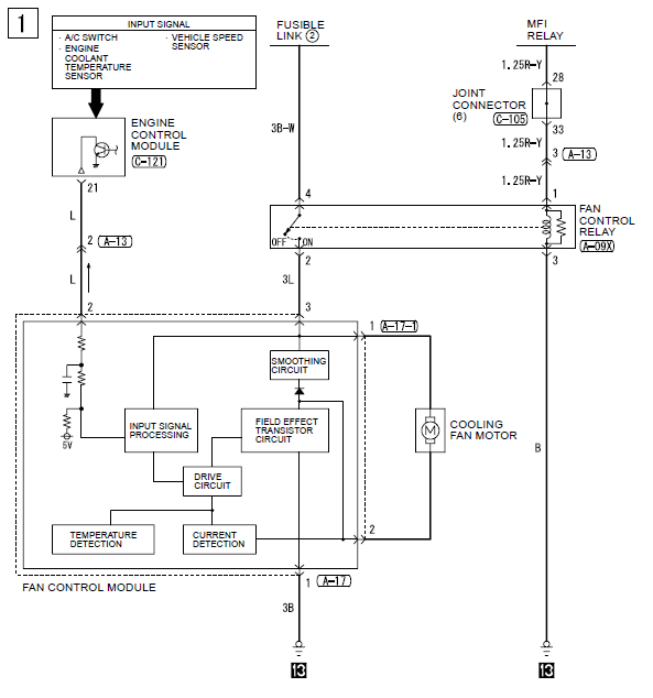
The manual doesn't say too much about the control module. However there is a specification for an output voltage of 8.2VDC when the engine is below normal temperature but the A/C is turned on. I assume this corresponds to roughly the minimum drive speed. I realize with a switching DC supply you can get an effective DC voltage even though the output might be a PWM square wave when running at reasonably high frequencies, 30-40Hz being plenty high.
There is however a block diagram of the control module and with the smoothing and drive current sense circuits, I'm thinking it does in fact provide a reasonable amount of smoothing, basically making this a PWM controlled motor drive controller. If that's the case, I just need to find another fan module.
There is however a block diagram of the control module and with the smoothing and drive current sense circuits, I'm thinking it does in fact provide a reasonable amount of smoothing, basically making this a PWM controlled motor drive controller. If that's the case, I just need to find another fan module.
I pulled the cover off a module and there are two reasonably large capacitors and an inductor coil in there. Looks to be a filtering circuit. I don't have a functional car to check this on with an O-scope, but I'm pretty sure the PWM module does in fact smooth the signal and effectively it is a PWM to DC-voltage converter.
I am not going to do the water pump for this season, just out of time and need to get the car back together now. However I'll write the code up this year and verify the code works on my car over the summer then do the water pump next winter.
I am pretty hopeful right now that it will turn out well and all the code and tables will simply replace the stuff the EGR system is currently using. I figure if anybody else wants to use this, they will be in a similar situation of building a racecar and the EGR is of little concern. It should make it reasonably easy to patch over to other ROMs as well as it will simply replace current RAM variables and code so there shouldn’t be a need to “find space” in other ROMs.
I might look at how the fan is controlled as well as the fan is able to stay running after the car is turned off. It would be nice if coolant kept circulating too so things cooled down uniformly.
Last edited by 03whitegsr; Mar 24, 2011 at 09:56 AM.

Thread
Thread Starter
Forum
Replies
Last Post
fostytou
Evo How To Requests / Questions / Tips
359
Oct 23, 2025 09:54 AM
Raceghost
ECU Flash
44
Feb 11, 2017 10:27 PM
Raceghost
ECU Flash
10
Jun 17, 2016 04:05 PM
Richard L
Water / Methanol Injection / Nitrous Oxide
149
Feb 27, 2016 03:01 PM